Generating reports
The program can generate and print job reports and reports on a selection of elements using the following options.
Job reports
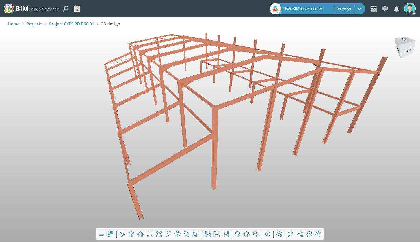
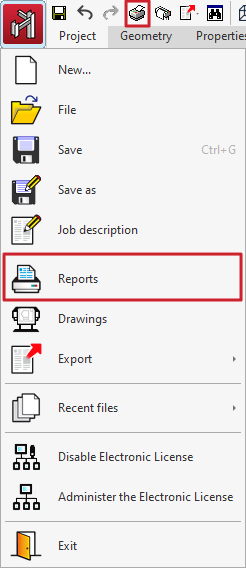
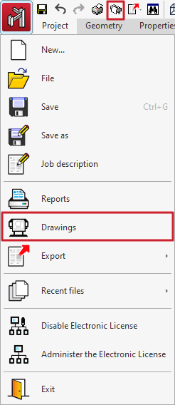
To obtain the job reports, open the "File" menu and select the "Reports" option, or use the "Reports" option at the top left of the program's main interface.
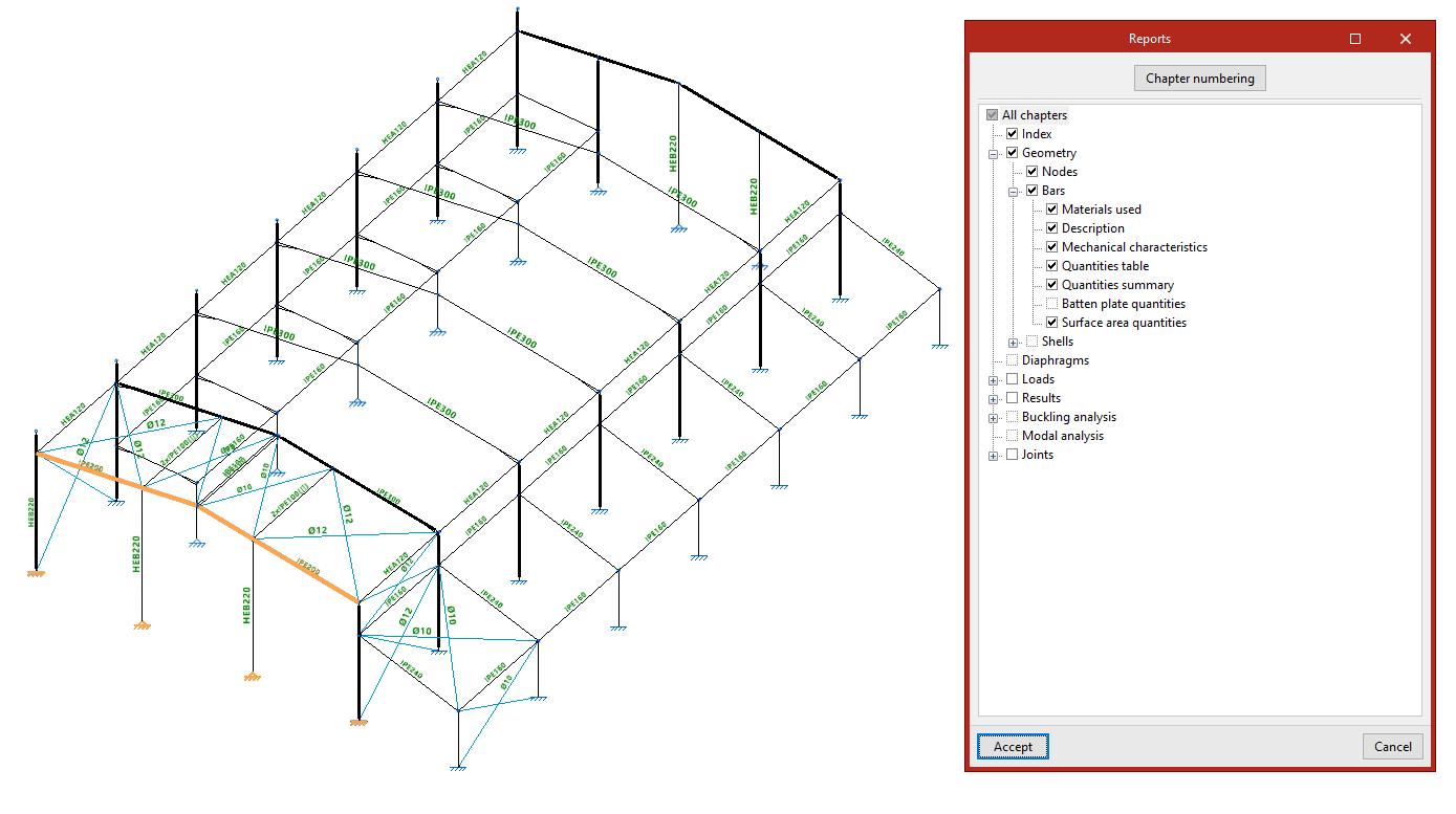
In the "Reports" window, check the corresponding boxes to print "All chapters" or a specific selection of them:
- The "Project data" chapter includes general information such as "Standards considered", "Limit states", "Earthquake", "Global stability analysis", and "Fire resistance".
- The "Structure" chapter includes the "Geometry" of the "Nodes", "Bars" and "Shells", as well as the "Loads", calculation "Results" and information on the "Joints". It also includes information on the defined "Diaphragms" and the "Buckling analysis" and "Modal analysis", if carried out.
- The last chapter includes the data and results of the "Foundation" if it has been entered into the model.
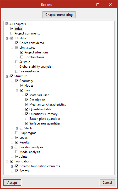
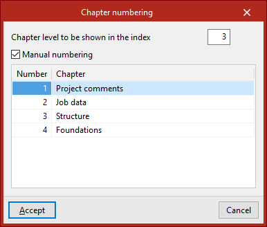
The "Chapter numbering" button at the top allows you to modify the "Chapter Level to Display in the Table of Contents" and carry out "Manual numbering" if desired, by typing the "Number" for each "Chapter".
Preview reports
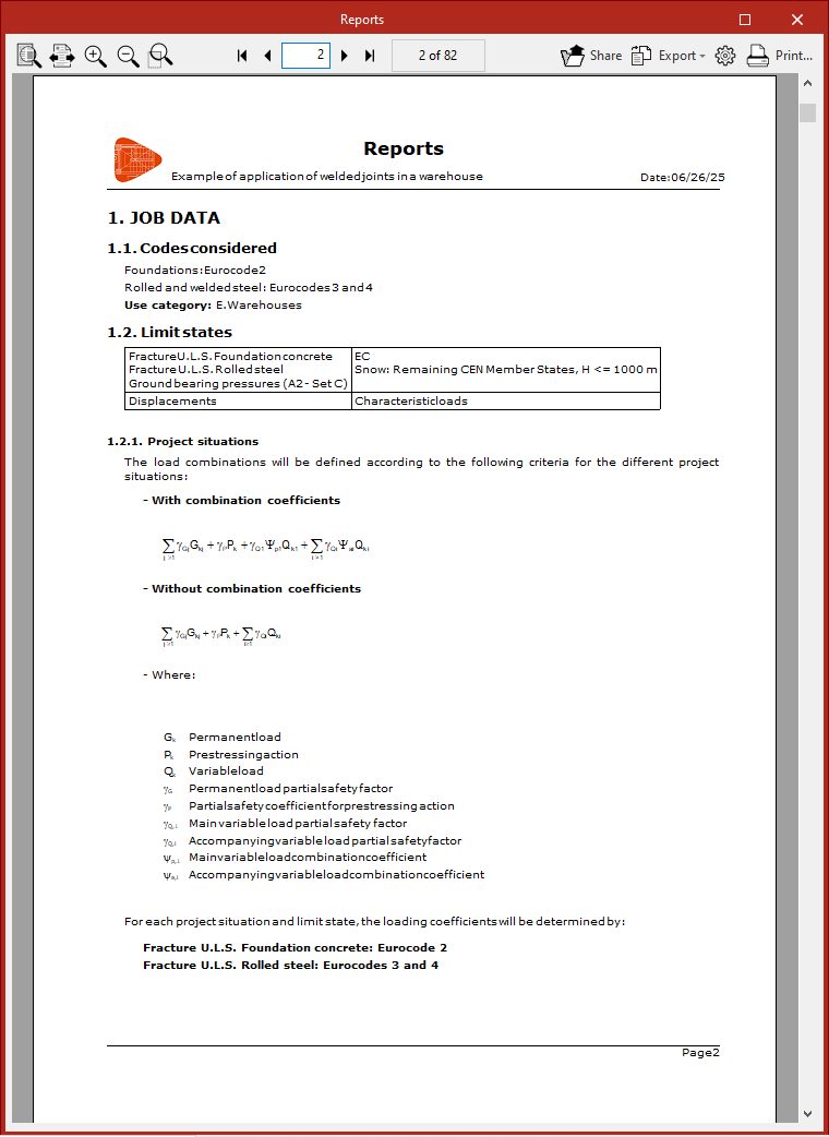
After selecting the desired chapters and clicking "Accept", the program displays a preview of the "Reports"
Here you can adjust the page size on the screen using the options available in the top left corner.
To scroll through the list, use the options in the centre, which allow you to move forward or backwards through the pages.
Further to the right, clicking on the "Share" option generates a private link that can be useful for showing the information to other users.
The report can be "Exported" in different formats, such as PDF, DOCX, TXT, HTML and RTF.
From "Print settings", select the printer and define the "Scale" and "Margins" of the document.
Finally, the "Print" option opens the document print dialogue, where you can define the "Pages to print" and other "Print settings".
Reports of selected elements
The program can generate reports of a selection of elements that make up part of the structure. To do this, use the "Selected elements" option in the "Reports" group of the "Project" tab in the "Structure" section.

After clicking on the option, select elements from the model by left-clicking on them one by one or by using the crossing method to select several elements simultaneously.
Right-clicking opens the "Reports" window, which contains the same options that appear when generating reports for the job.
In this case, the program will only list the information for the selected elements and not for the entire structure.
Generating drawings
To generate and print the drawings for the job, open the "File" menu and select the "Drawings" option, or use the "Drawings" option at the top left of the program's main interface.
This opens the "Drawing selection" window.
Selecting drawings
The "Drawing selection" window is used to manage the list of drawings for the job.
The first option on the top toolbar allows you to "Add" a drawing. When you click on it, the "Drawing editing" window opens, where you can select and configure the desired drawing.
After accepting the "Edit drawing" window, the drawing is added to the list in the "Drawing selection" window. This process must be repeated to add all the desired drawings to the job.
At the top, the program offers utilities to "Edit", "Copy", "Delete" and move or reorder drawings in the list.
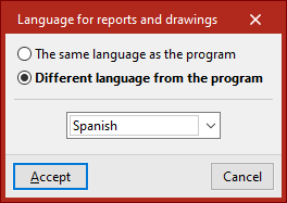
There is also a tool for modifying the "Language for reports and drawings". This can be "The same language as the program" or a "Language different from the program", in which case you will have to choose from the drop-down menu.
The list of drawings is organised as a table with different columns, which work as follows:
- The program prints the drawings that have the "Draw" box enabled.
- The "Drawing type" column provides information about the type of drawing selected.
- When the "With textbox" box is checked, a box indicating the type of drawing and its scale is added to the drawing.
- Further to the right, the "Peripherals" are selected. Drawings can be exported in DWG or DXF format or printed directly using graphics devices and printers that can be configured in the program, including export to PDF.
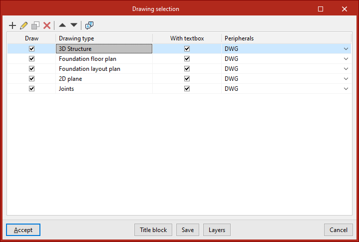
A series of additional options are displayed at the bottom of the window:
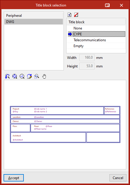
- With the "Title block" option, you can import a title block from a .dwg or .dxf file, use a predefined title block, or reserve an "Empty" space on the plan to manually add the title block later in another drawing program.
- The "Save" option allows you to save the selection of plans made and exit the window without generating the drawings.
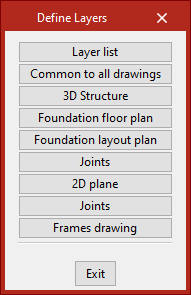
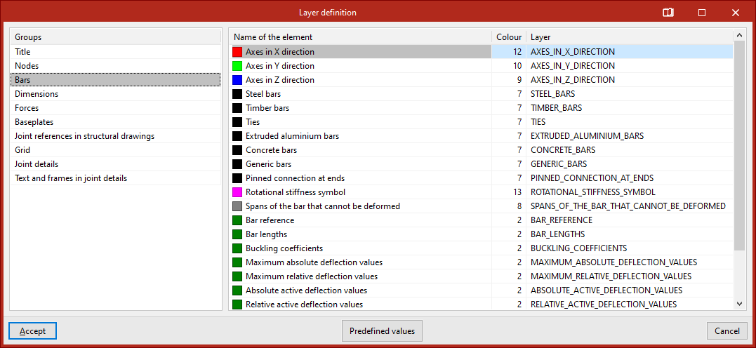
- From "Layers", you can view and modify the name and colour number of the layers generated in all types of drawings. The colour number may be associated with a different colour in each drawing program.
Editing the drawing
The first option in the "Drawing selection" window allows you to "Add" a drawing. This will open the "Drawing edit" window.
First, select the "Drawing type" from the drop-down menu. The available types include the following:
- 3D structure
- Foundation floor plan
- Foundation layout drawing
- 2D drawing
- Connections
Configuring "3D Structure" type drawings
If you select "3D structure" in the central table, you can enable or disable the printing of the different 3D and 2D views of the model previously created from the options in the "Window" tab.
Next, enter the "Scale" of the drawing.
In "Section", indicate whether the program should only draw the "Axis" of the bars or represent their "Actual" section.
By activating the lower boxes, you can incorporate additional information into the drawings, such as the following:
- Section type
- Bar lengths
- Node references
- Bar references
- Element references
- References of the applied joints
- Welds
- Bolts
- Baseplates
- Column references
- Beam references
- Sheet references
- Integration strips
- Required resistance
- Protective coating
- Critical temperature
By checking the boxes on the right, you can include information on buckling coefficients, limit deflections and end fixings in the "XY", "XZ" and/or "YZ" drawings for each bar:
- Buckling coefficients
- Absolute maximum deflection limit
- Relative maximum deflection limit
- Absolute active deflection limit
- Relative active deflection limit
- Fixity at ends
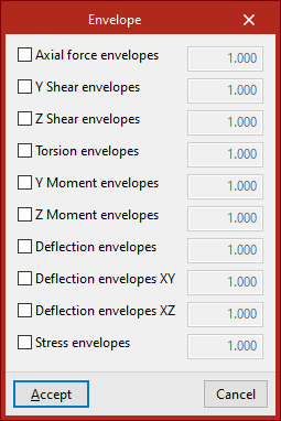
From "Envelopes" at the bottom, you can activate the visibility of the graphs of the stress, deflection and strain envelopes.
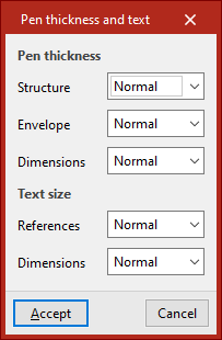
The "Lines and texts" option allows you to modify the thickness of the "Lines" of the elements in the plan and the "Text size".
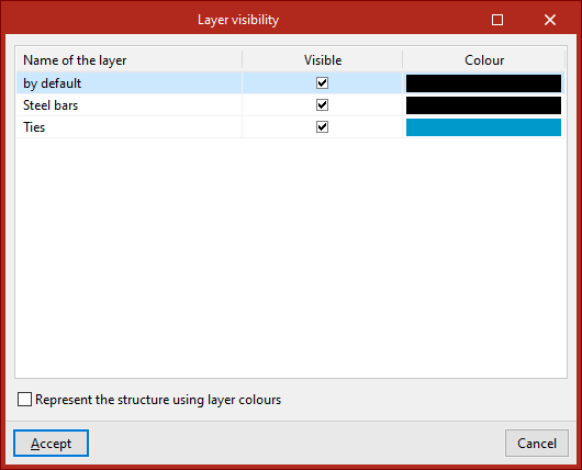
You can also manage the "Layer visibility" by clicking on the corresponding button. In the pop-up window, the different boxes are activated or deactivated to make each of the layers or the elements contained in them visible. If desired, you can "Represent the structure using layer colours".
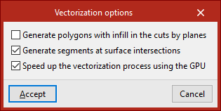
Finally, editing the "Vectorisation options" is possible in drawings that represent profiles with their actual section and allow them to be adjusted. These are as follows:
- Generate polygons with fill in cuts by planes
- Generate segments at surface intersections
- Speed up the vectorisation process using the GPU
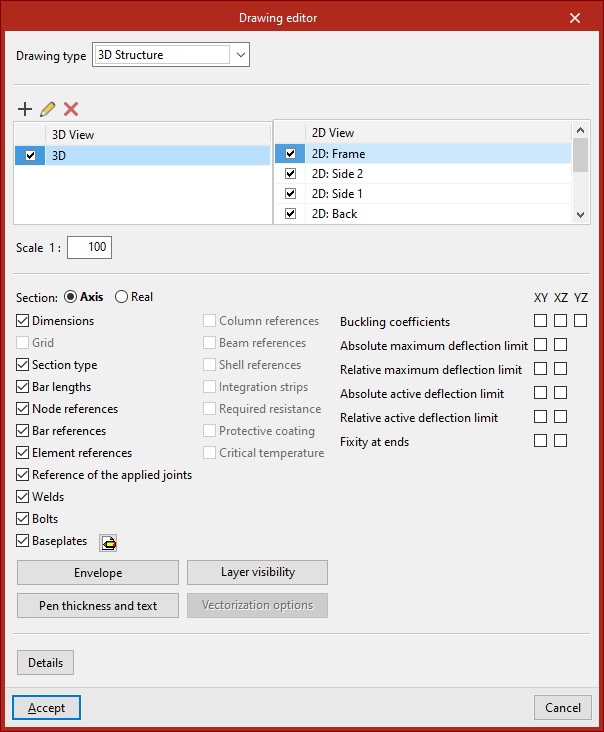
Details
Optionally, construction details can be added to the drawing. To do this, click on "Details" at the bottom.
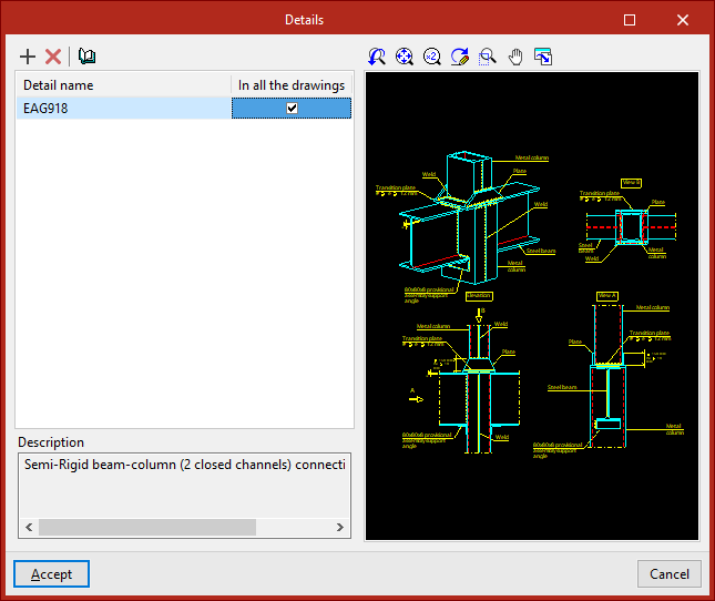
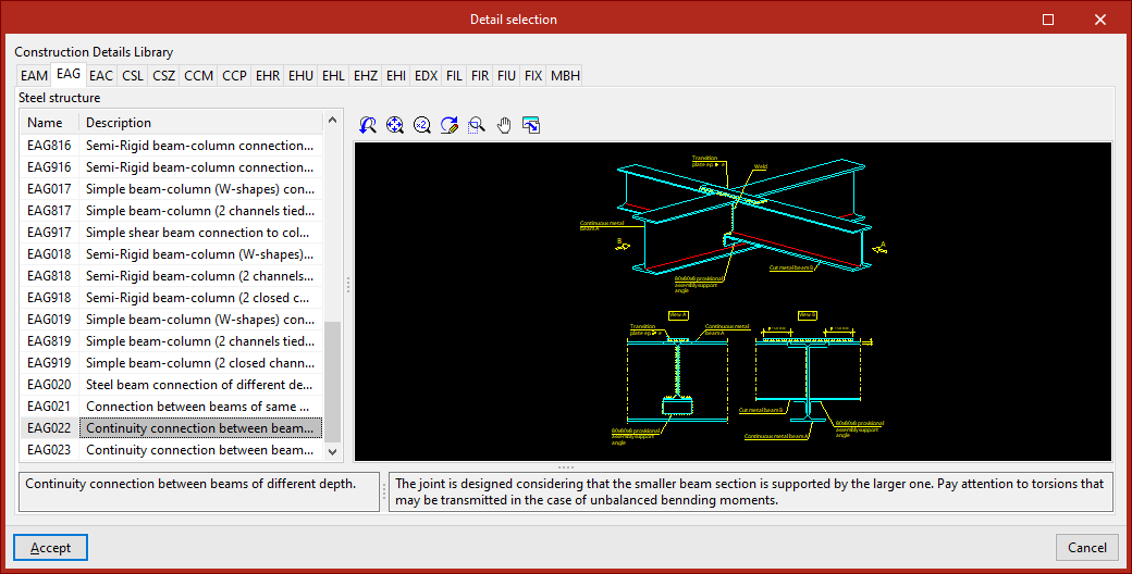
In the window with the same name, clicking on "Add" will take you to the program's "Construction details library", where all the available details are displayed, organised into different tabs. After selecting a detail, click on "Accept" to add it to the drawing. You must indicate whether the detail is to be shown "In all drawings" or not.
It is also possible to "Add user detail" by creating your own detail library and uploading DXF or DWG format files saved on disk.
After clicking "Accept", you will return to the "Edit drawing" tab.
Generating and printing drawings
Once all the desired drawings have been loaded into the list, accepting the "Drawing selection" window opens the "Drawing composition" window, which provides a preview of the drawings to be generated and the drawings they contain.
In this window, several limited operations can be carried out:
- New drawing
Creates a new drawing by choosing its format. - Delete empty drawings
Deletes empty drawings that do not contain any drawings. - Centre all drawings
Restores the original position of the drawings in all drawings. - Centre selected drawings
Restores the original position of the drawings in the selected drawings. - Edit drawing
Move elements (such as text) within each drawing. - Move drawing
Move selected drawings to change their position or placement in different drawings.
The drawings located in the plans are shown with no detail so that the equipment consumes fewer resources and allows the aforementioned operations to be carried out more quickly. If you wish to see the detailed content of the drawings, use the following options:
- Drawing details
Displays detailed information contained in the selected drawing. - Details of all drawings
Displays detailed information contained in all drawings.
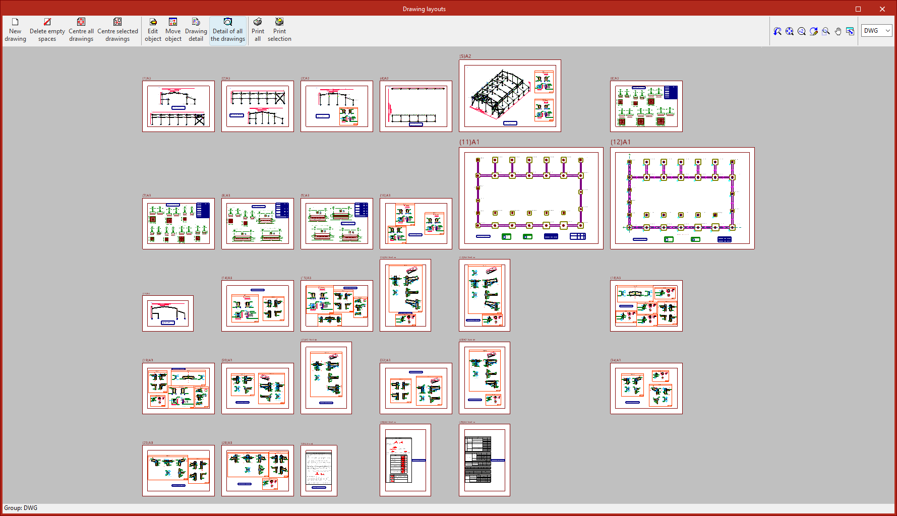
Finally, to print the drawings, the following options are available:
- Print all
Prints all the drawings. - Print selected
Prints only the selected drawings.
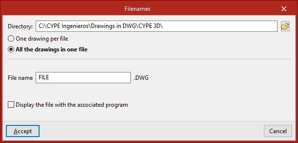
If you have previously selected export to .dxf or .dwg files, the program will ask you to specify the "Directory" and "File name".
If you have selected multiple drawings, you can also choose whether each drawing is included in a separate file (which will generate a set of files), or whether all drawings are generated in a single file:
- Each drawing in a separate file
- All drawings in a single file
When clicking accept, the drawings are generated in the selected directory. Optionally, if only one file is being generated, you can "Display the file with the associated program" for reading that file format.
BIMserver.center linking options
The options in the "BIMserver.center" group, found in the top toolbar of the "Project" tab, allow you to link the project and export information to a BIMserver.center project.

To use these options, you must first "Log in" to BIMserver.center using the corresponding button on the right side of the program’s title bar.
Link
The first option allows you to "Link" the project to a BIMserver.center project.
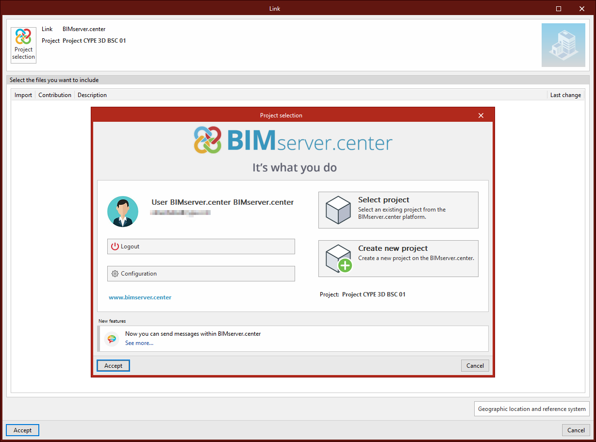
In the window that appears, click on "Project selection". Here, you can use the "Select project" option to choose a previously created BIMserver.center project, or create one on the spot using "Create new project".
In this case, enter the "Project name", select the "Owner", "Project type", "Visibility options", "Collaboration request management", and add a "Description".
You can also indicate whether you wish to "Review new contributions" or "Review updated contributions" by checking the boxes at the bottom.
Then, click "Accept".
Unlink
In the "BIMserver.center" menu, you can also "Unlink" the project from its associated BIM project.
Consultar
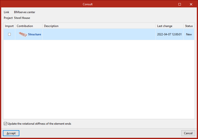
The next option allows you to "Consult" the status of the project to which the current project is linked.
In the lower table of the window, if there are other files in the BIMserver.center project, they can be "Imported" for 3D visualisation. You can also check the "Application" used to generate them, as well as the "Contribution name", its "Description", the "Last modified" date, and its "Status".
A checkbox at the bottom allows you to "Update the rotational stiffnesses at member ends". This option imports the rotational stiffness of connections calculated in CYPE Connect or StruBIM Steel (and exported to BIMserver.center) into the original CYPE 3D structure.
Share
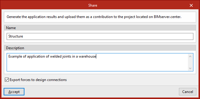
The final option in this group allows you to "Share" the model information to the BIMserver.center project.
You must enter the "File name" that will be generated during the export process, along with a "Description".
If you want to "Export forces for connection design", you can enable the checkbox at the bottom. This way, the force data calculated at the ends of structural elements can be used in the design of connections by other programs like CYPE Connect or StruBIM Steel.
After clicking "Accept", the program starts the export process and uploads the model information to BIMserver.center.
From that moment on, the information becomes available for viewing on the BIMserver.center web platform, under the "Projects" section.
The model generated with CYPE 3D can also be read by other applications linked to BIMserver.center.