
Reinforcement tab options
The top "Reinforcement" tab (accessible from the lower "Structure" section) contains the tools for detailed editing of the reinforcement and/or the sections of columns and beams that have been inserted into the model using the corresponding options in the "Geometry" tab.
The upper ribbon includes:
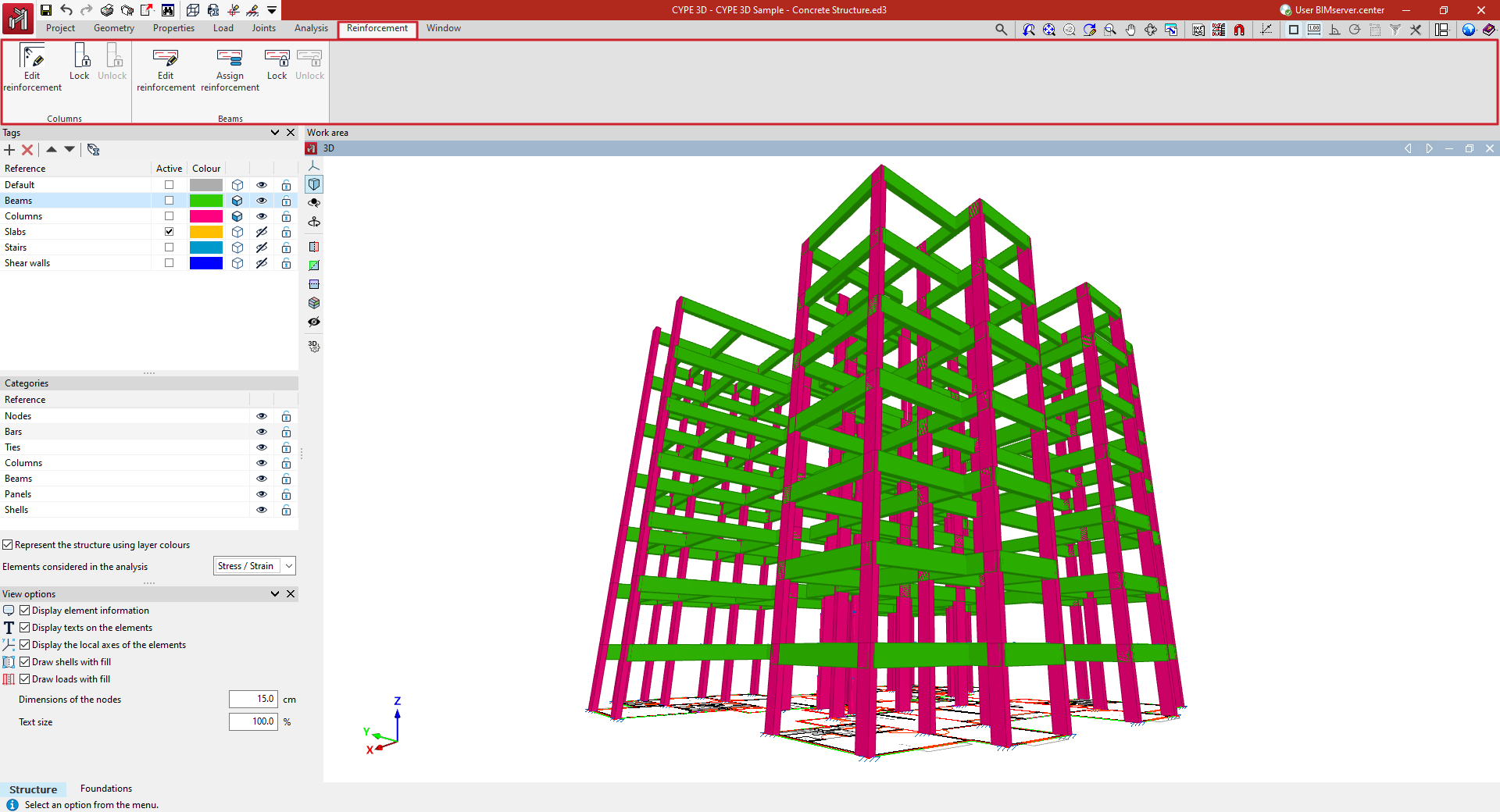
- In the "Columns" group, the option to edit the reinforcement and/or sections of the columns by accessing their editing panel, as well as options to lock or unlock column reinforcement so that it is not modified during the analysis;
- And in the "Beams" group, the option to edit the reinforcement and/or sections of the beams by accessing their editing panel, as well as options to assign the reinforcement of one beam to others, and lock or unlock beam reinforcement so that it is not modified during the analysis.
Accessing the column editor
The "Edit reinforcement" option, found in the "Columns" group of the top toolbar in the "Reinforcement" tab (under the "Structure" section), allows you to access the column editor.
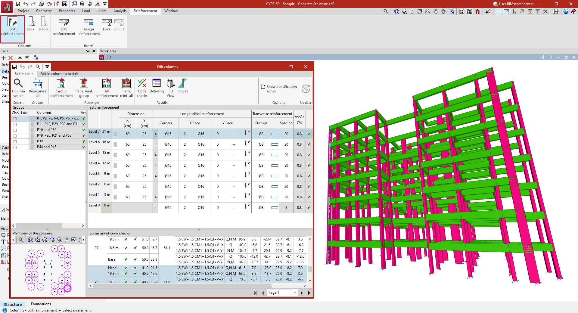
To do this, select the column you wish to consult in the workspace using the left mouse button. This opens the "Column editing" window, which displays the built-in column editor of the program.
Editing columns in the table
In the column editor, the forces, design and checks carried out automatically by the program on all the columns in the job and on all its sections can be consulted. Users can also organise and resize the groups of columns, modify the reinforcement or the steel sections used and check all the modifications made, generating detailed check reports.
The window has two tabs, "Edit in table" and "Edit in column schedule". Either of these editing interfaces allows users to consult and modify the columns. They differ in the possibilities of editing and reviewing results and in the view on which they are performed. Any of them can be chosen, as the information is linked.
The "Edit in table" tab displays the information in four sections.
- Groups
- Plan view of the columns
- Edit reinforcement
- Summary of code checks
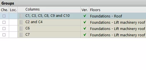
Groups
Firstly, the "Groups" section in the top left-hand corner allows users to select between the different sets or groups of columns that the program has created during the analysis. The columns in the same group share the same cross-section geometry, number of floors and reinforcement.
In this table, it is marked whether the group has been "Checked" or "Locked" if no changes are to be allowed. It is also indicated whether or not the group ", is “Verified" in accordance with the specifications of the selected standard, and the "Floors" it passes through.
Plan view of the columns
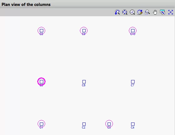
The “Plan view of the columns” section in the top left-hand corner shows a schematic plan view of the distribution of all columns in the model, with those belonging to the selected group in a magenta circle.
Edit reinforcement
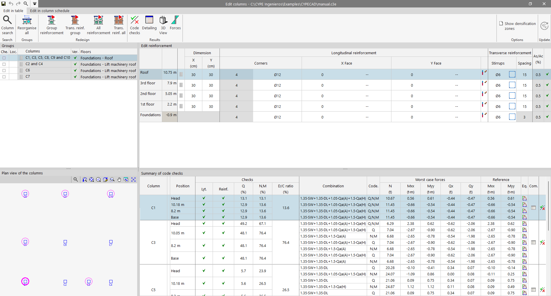
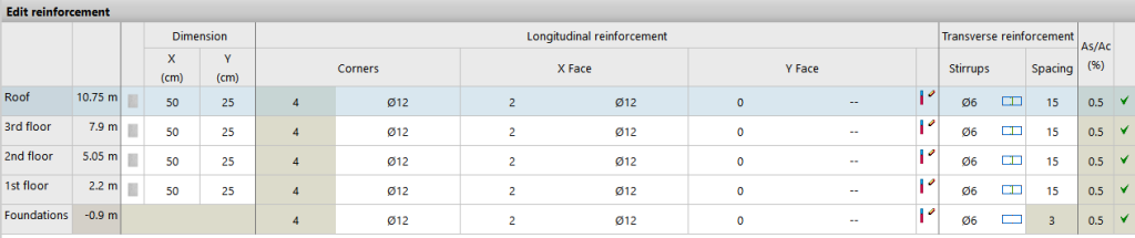
The “Edit reinforcement” section in the top right-hand corner constitutes the main editing area.
It shows the floors through which the columns of the selected group pass, indicating their height and the "Dimension" of each section. For reinforced concrete and composite columns, the "Longitudinal reinforcement" obtained in the analysis is shown, both for "Corners", "X Face" and "Y Face", and the "Transverse reinforcement", including the definition of the "Stirrups" and their "Spacing".
The "Geometric quantity" [As/Ac (%)] is also shown, and a checkmark for the span indicates whether or not all the checks carried out on the section are complied with.
The program allows columns to be edited in this table by clicking on any of the cells contained in the aforementioned rows and modifying the data by typing them in directly or by selecting them from the different drop-down menus.
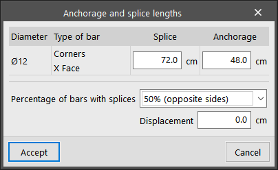
To edit the "Anchorage and splice lengths" of the reinforcement, click on the button to the right of the longitudinal reinforcement of the Y face. You can modify the "Percentage of bars with splices". If the overlap is equal to 50% of opposite sides or alternating bars, you can apply a "Displacement" to it.
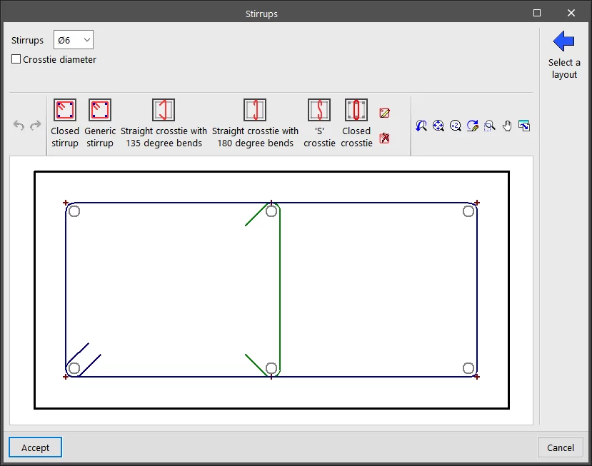
By clicking on the cell where the "Stirrups" are drawn, they can be edited. At the top, the diameter of the "Stirrups" is defined, and optionally, the "Crosstie diameter". At the bottom, the program allows a specific layout of stirrups and crossties to be added from those available. The "Select a layout " option can be used to preload a configuration of stirrups and crossties from the reinforcement tables.
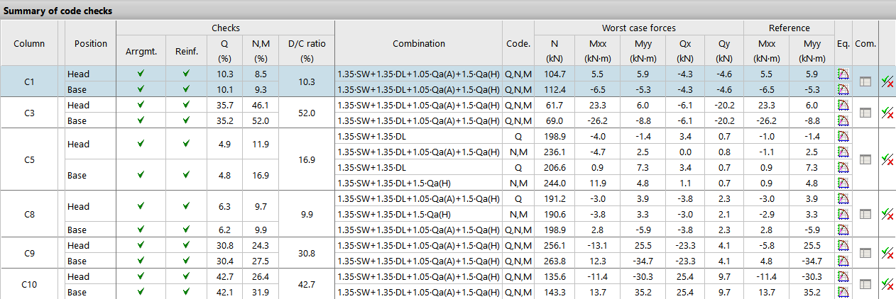
Summary of code checks
By selecting any row in the "Edit reinforcement" table, corresponding to a column span, the "Summary of code checks" section in the lower right-hand corner displays the information of the most relevant code checks for that column span.
For each "Column", the "Position" of the check sections of the span, either at the "Head" or at the "Base" of the span, is indicated.
The different columns show the numerical values calculated for the most important "Checks", including the maximum "Demand capacity ratio" of the section and the "Combination" of loadcases in which it occurs.
The "Worst case forces" are those with which the section has been reinforced, while the "Reference" forces are those obtained directly from the resolution of the matrix analysis and prior to operations such as the moment amplification.
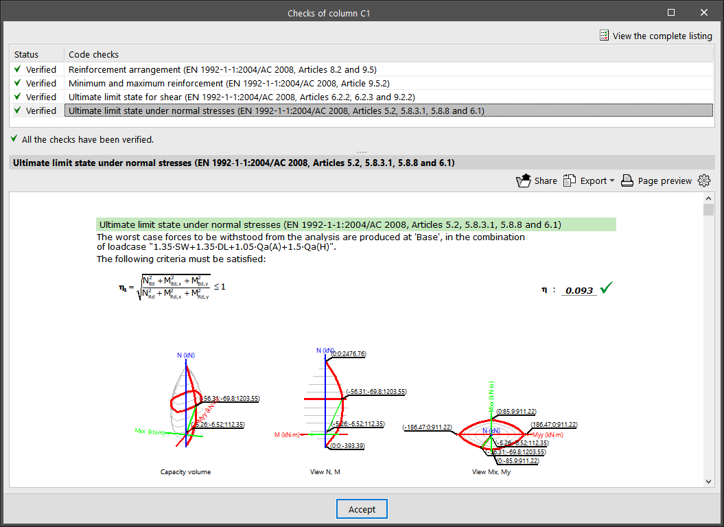
On the right-hand side, the "Equilibrium diagram of the section for the selected combination" and the "List of the checks undertaken for all the combinations" are shown.
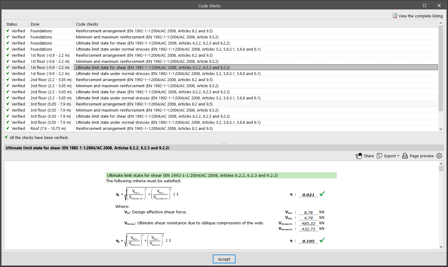
By clicking on the last button, you can access the list of "Code checks" for the selected column span. Here, all the checks carried out are displayed one by one, including a mark with their "Status". At the bottom, the section or article of the verified code is indicated, as well as an explanation of the analysis that has been carried out for each one of them. For a detailed report of all the checks, click on "View the complete listing". Users can "Export" the information in different formats, "Share" it or "Print" it.
Other options
At the top of the "Edit columns" window, there are a number of tools with different functions.
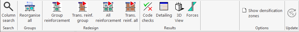
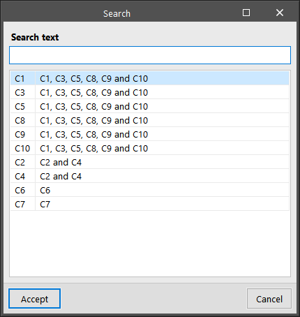
- First, users can carry out a "Column search" by indicating its reference or they can click on "Reorganise all" to reorganise the groups of columns by their reference.
- In the “Results” group, the “Redesign group reinforcement”, “Redesign trans. reinf. group”, or “Redesign all reinforcement” options allow the program to automatically retrieve the reinforcement of the selected column groups after any modifications using the available reinforcement tables.
- The "Code checks" option allows users to obtain the list of ultimate limit state checks for all the sections of the selected column. Users can "Export", "Share" or "Print" this information in the same way as the partial check reports shown above.
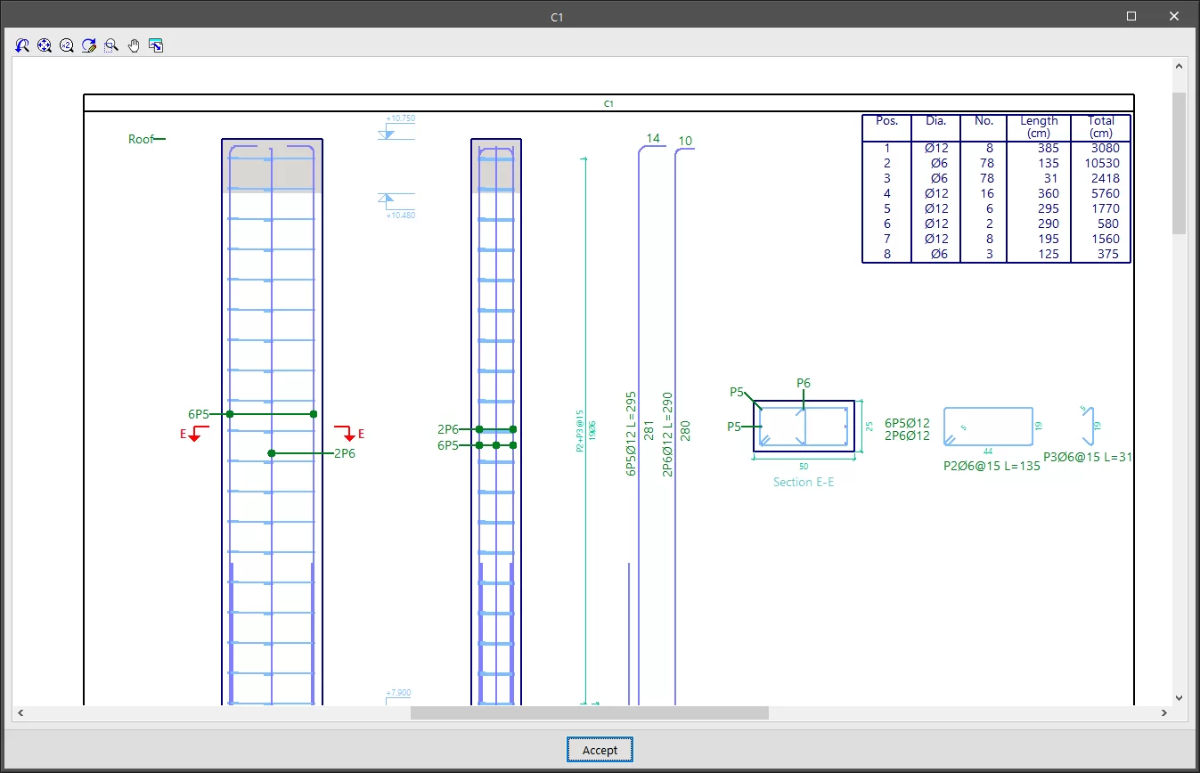
- "Detailing" provides a view of the column with a detailed and dimensioned layout of all reinforcement, including their measurements in a table of ratios.
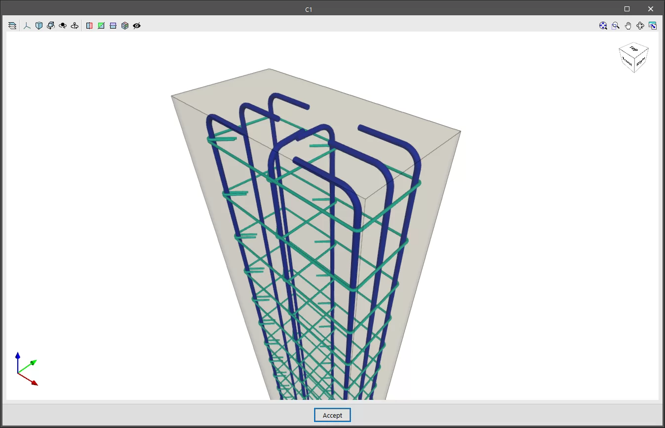
- "3D View" shows the section and reinforcement of a column in a fully three-dimensional environment.
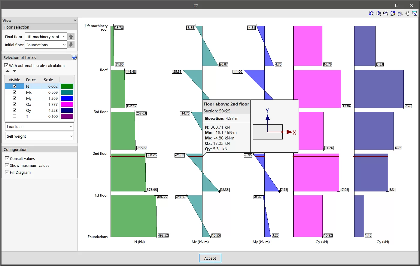
- The "Forces" option allows you to view the axial, moment, shear and torsional diagrams of the selected column. To do this, the visible floors and forces are selected, as well as their "Scale". The desired "Loadcase" or "Combination" can be selected from the drop-down menus. Then, by moving the mouse pointer over the diagrams, the program will display the information on the values of the forces for the section located at the indicated dimension and for the selected loadcase or combination.
- The "Show densification zones" option shows or hides the different stirrup sections in the "Edit reinforcement" table that a concrete or composite column can have, depending on the options considered in the analysis. This option does not allow users to add any more different densification zones. To do so, they must go to the "Edit in column schedule".
- Finally, the "Update" option allows the check results to be updated after any changes have been made.
| Note: |
|---|
| Lastly, it should be noted that if major modifications are made to column sections, a complete analysis of the job is recommended, as there may be significant variations in the forces to which they are subjected. |
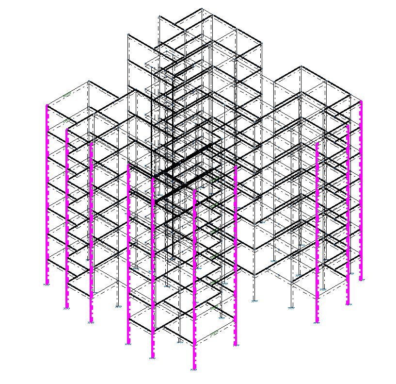
Locking and unlocking reinforcement of columns
The options for locking or unlocking the reinforcement of concrete columns are located in the "Columns" group of the top toolbar, within the "Reinforcement" tab (in the "Structure" tab).

Lock/Unlock
To lock or unlock the reinforcement of columns, after clicking the option, you must select the columns one by one or use a selection area in the workspace. Then, right-click.
Columns with locked reinforcement are displayed in magenta in the viewer.
Locking the reinforcement of columns ensures that it is not modified during the reinforcement design process carried out by the program when calculating the structure.
| Note: |
|---|
| It is also possible to lock the reinforcement of a group of columns using the corresponding option within the "Groups" section of the column editor, accessible via the "Edit" option in the "Columns" group. |
Accessing the beam editor
The "Edit reinforcement" option, within the "Beams" group of the top toolbar in the "Reinforcement" tab (in the "Structure" tab), allows you to access the beam editor.
To do this, select the frame you wish to view in the workspace using the left mouse button. This opens the "Edit reinforcement" window, which displays the beam editor built into the program.
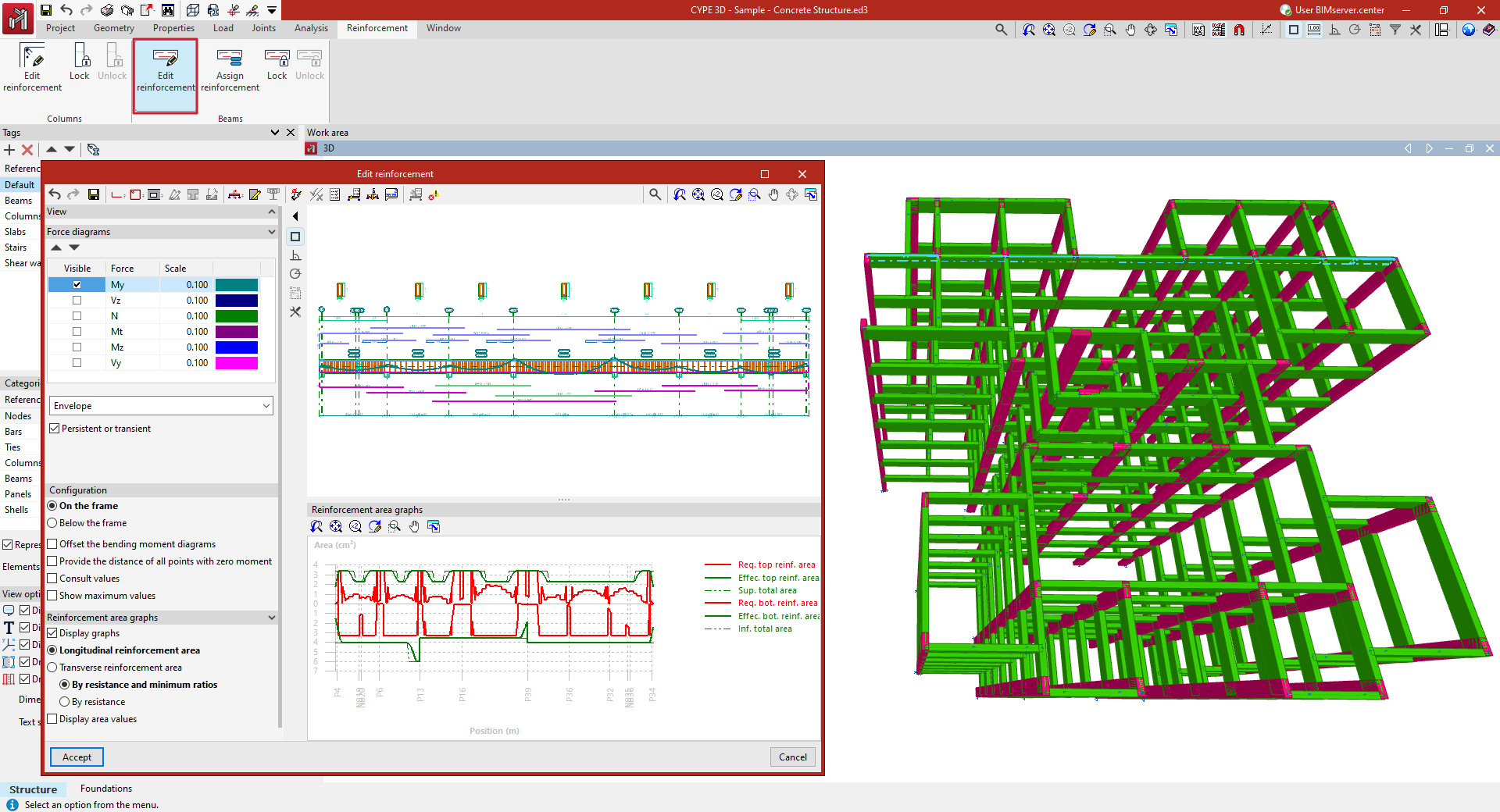
Beam editor
The beam editor allows users to review the internal forces, design, and checks automatically performed by the program for all beams in the job. Using the editor, you can modify the reinforcement or steel sections used and verify all the changes made, then generate detailed check reports.
Beam editor interface
The interface of the beam editor includes the following areas and features:
Top toolbar
- At the top of the window, various editing and verification tools are available for the beams in the displayed frame.
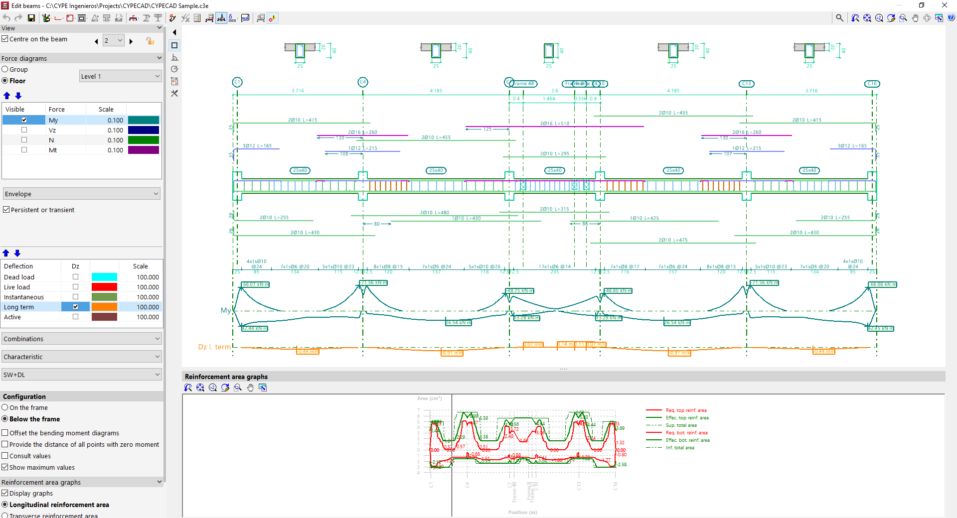
Viewers
- The main viewer in the upper right displays a longitudinal section view of the frame being edited. For reinforced concrete beams, it shows the longitudinal and transverse reinforcement generated after calculation. At the top, the generated cross sections are also shown.
- The secondary viewer at the bottom displays the "Reinforcement area graphs". The required area is shown in red, and the effective area of the placed reinforcement in green. The most critical or most used points in terms of reinforcement are those where the effective reinforcement graph is closest to the required reinforcement graph.
Side options panel
- On the left side, in the "Display" section, the program indicates the "Group" and the "Frame" currently shown in the viewer. The "Centre on beam" option allows you to centre the view on the desired beam, while activating "Plan view of frames" adds a schematic plan view. Clicking the left and right arrows allows you to navigate to the next group, frame, or beam. It is also possible to lock the reinforcement of the frame using the corresponding button. This will prevent the program from modifying the frame’s design in subsequent analyses, but it will not prevent manual edits in the editor.
- In the "Force diagrams" section, visibility of various internal forces is enabled, along with their scale and colour, such as the bending moment, shear force, axial force, or torsional moment.
- The lower dropdown menu lets you choose whether to view the "Envelope" of forces or one of the available "Load cases" or "Combinations"
- If the options "ULS and SLS checks at critical point", "ULS and SLS checks at a point", or "Check deflection in spans" are selected at the top, additional options for "Deflection" appear in this side panel, which can be reviewed in the same way as the force diagrams.
- In the "Configuration" subsection, you can choose whether the force diagrams are shown "Above the frame" or "Below the frame". Additional options include "Offset bending moment diagrams", "Mark zero moment points", and "Show values", which allows hovering over the diagram to see the force value at a specific section, as well as "Show maximum values".
- In the "Reinforcement area graphs" section, the "Show graphs" option toggles the display of the secondary viewer. Users can select whether to display the "Longitudinal reinforcement area" or the "Transverse reinforcement area", and whether to show it "By resistance and minimum ratios" or only "By resistance". It's also possible to "Show area values" in the viewer by enabling the last option.
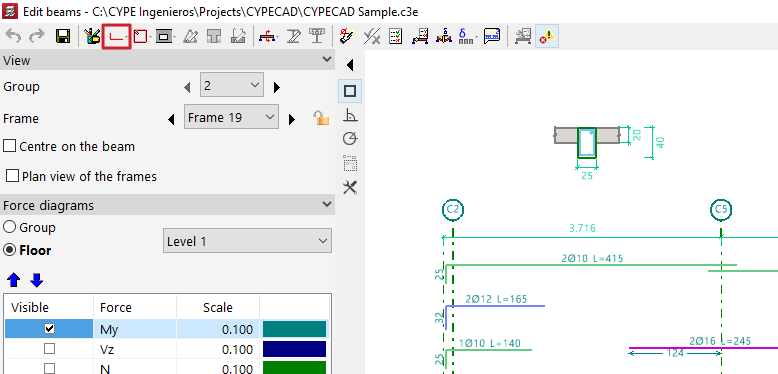
Beam editor tools
The tools at the top of the beam editor allow the following operations to be performed.

- First, it is possible to "Redo", "Undo", or "Save" the changes made using the options described below
- The "Editing resources" button (available in CYPECAD) allows you to insert graphic aids such as lines, text, and dimensions on the drawing.
- Further to the right, there are options to modify the "Longitudinal reinforcement" and "Transverse reinforcement of the beam", as well as to insert "Openings" in the beam.
- For specific cases involving truss beams and prestressed beams, it is possible to modify the "Trusses", "Infilled" beams, and the selection of "Prestressed beams".
- The "Transverse sections" option allows them to be generated automatically, to "Enter a transverse section defined by a single point" or "Enter a transverse section defined by two points", and to delete them. Cross sections are displayed above the frame.
- The "Edit section" option allows the beam's section to be modified.
- "Shear studs for composite beams" can also be modified for this type of beam.
- The "Redesign" option forces the program to automatically re-design the frame using the internal forces from the analysis, applying the reinforcement tables and discarding any manual modifications made.
- The "Checks" option allows you to examine the series of sections used in steel, composite, or timber beams. The program displays a table indicating the "Section that passes all the checks" and the "Section that fails a check", along with the reason stated in the "Errors" column. It also displays each section’s "Weight", "Usage due to resistance", and "Demand capacity ratio - deflection". Selecting one and accepting will result in a section change.
- By selecting "U.L.S. and S.L.S. checks at the worst case point" and then clicking on a beam, the program shows the results of each check at the most unfavourable point. All performed checks are shown individually, each marked with its "Status". At the bottom, the verified code clause or article is displayed, along with a breakdown of the analysis process followed in each case. To obtain a detailed report of all checks, use the "View full report" option. This information can be "Exported" in different formats, "Shared", or "Printed".
- To obtain "U.L.S. and S.L.S. checks at a point", click on the corresponding option and then select the desired beam. The program will show a series of points along the beam, representing the locations of the verification sections. Clicking on any of them displays the specific check report for that point. As with the previous option, you can "View full report", as well as "Export", "Share", or "Print" the information.
- The "Consult deflections in spans" option allows you to move the pointer over the spans of the selected beam to display the calculated deflection information.
- Additionally, the "Deflection groups" option (available in CYPECAD) allows automatic generation or manual editing, as well as merging or splitting of existing deflection groups. It is also possible to modify the "Support conditions" of the beam by selecting one of the available predefined cases, and to define the "Deflection type" as "Secant deflection", "Tangent to start node", or "Tangent to end node".
- Similarly, the "Consult the required and effective areas" option allows you to move the cursor along a beam and view the steel areas at the point where the pointer is located.
- The "Update error information" option forces the program to recheck the frame after modifications have been made to its section or reinforcement. After using this option, you can return to the check reports and review the outcome of the changes.
- Lastly, the "Show/Hide issues" option enables or disables the display of issues. These are shown in the main viewer over the beam with problems. Hovering the pointer over them displays an informational message explaining the issue.
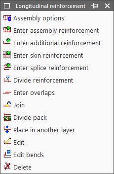
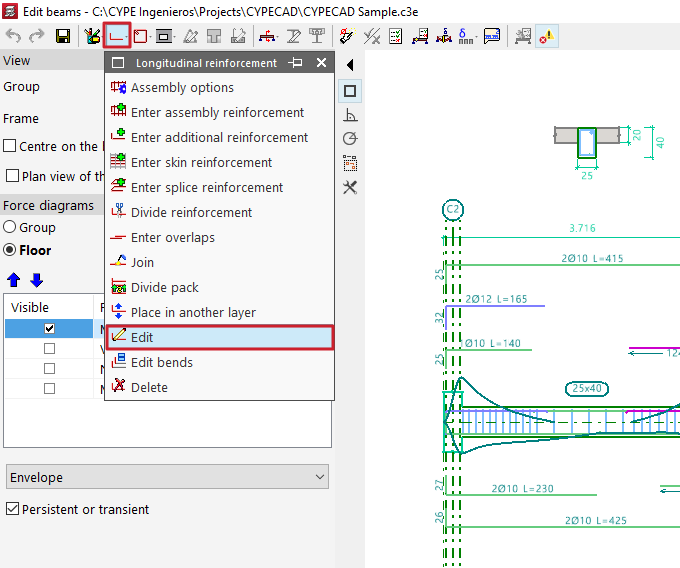
Editing longitudinal reinforcement of beams
The editing tools for longitudinal reinforcement are located at the top of the beam editor window and include the following:
- Assembly options
- Enter assembly reinforcement
- Enter additional reinforcement
- Enter skin reinforcement
- Enter splice reinforcement
- Divide reinforcement
- Enter overlaps
- Join
- Divide pack
- Move to another layer
- Edit
- Edit bends
- Delete
These options are explained below:
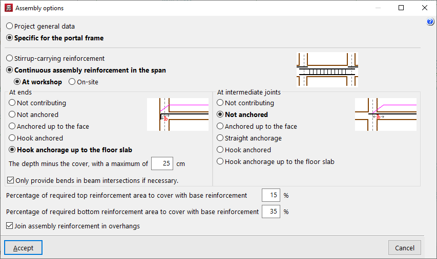
Assembly options
This option allows you to choose whether to use the general configuration for assembling reinforcement defined in "General project data" (Project > General data > By position > Beam options > Design / Check > Mounting reinforcement) or to use the options "Specific to the frame".
Enter assembly reinforcement
The "Enter assembly reinforcement" option allows you to select a beam that does not already have defined assembly reinforcement, or to define the initial and final nodes of the assembly reinforcement cage, as long as they are aligned.
Next, you specify the top and bottom reinforcement, the layout of the transverse reinforcement, and the bend definitions at the bar ends.
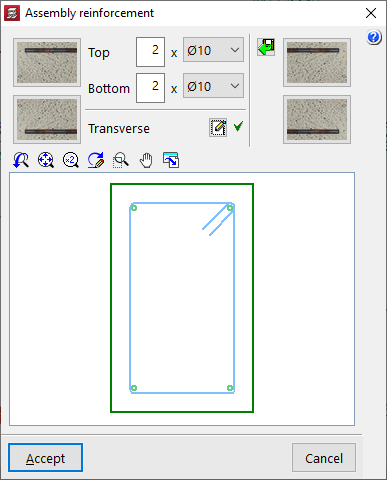
The program also allows you to "Import an admissible arrangement from the assembly reinforcement table" by clicking the button on the right. After selecting a row in the table, accept the panel.

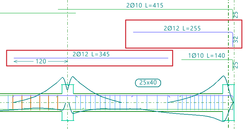
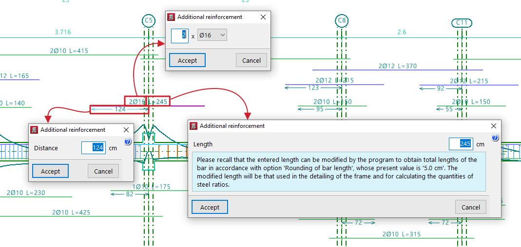
Enter additional reinforcement
To "Enter additional reinforcement", you define the number of bars and their diameter. Optionally, you can "Select the layer upon entering the reinforcement".

Then, position the pointer on the top or bottom of the frame, depending on where the reinforcement is to be placed, and click two points to define the spacing between the ends of the reinforcement bundle.

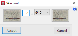
Enter skin reinforcement
To "Enter skin reinforcement", simply click on the beam and specify the number and diameter of the bars.
This reinforcement will be placed on both sides of the beam.

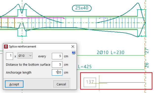
Enter splice reinforcement
To "Enter splice reinforcement", click one end of the beam, move the pointer inward across the span, and click again to indicate the "Distance" between bars.
Next, define the number and diameter of bars, spacing, "Distance to the bottom surface", and "Anchorage length".

Divide reinforcement
The "Divide reinforcement" option allows you to select a point on a reinforcement bar and introduce a lap, splitting the bar into two bundles.
In the "Lap layout" section of the dialogue box, you can select the lap type:
- Lap centred on the selected cut point
- Lap to the left of the selected cut point
- Lap to the right of the selected cut point
At the bottom, you specify the "Lap length".

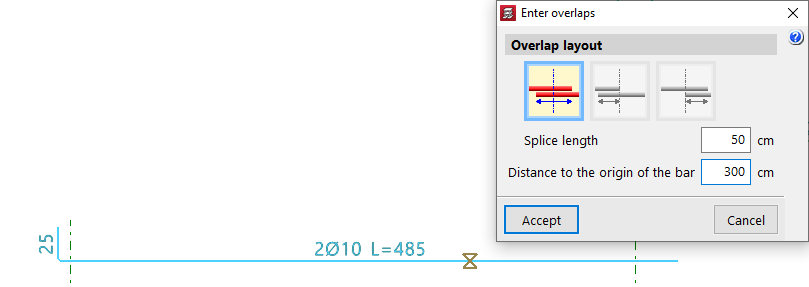
Enter overlaps
The "Enter overlaps" option allows you to select a point on a reinforcement bar and enter a lap without splitting the reinforcement group.
As with the previous option, in the "Lap layout" section, you can choose:
- Lap centred on the selected cut point
- Lap to the left of the selected cut point
- Lap to the right of the selected cut point
You also define the "Lap length", and additionally, the "Distance to the origin of the bar".
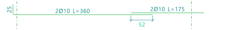
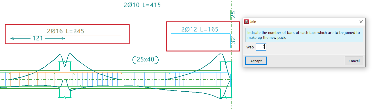
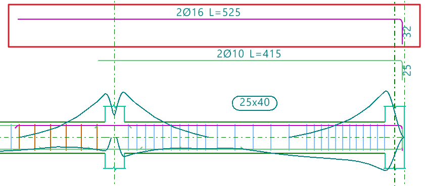
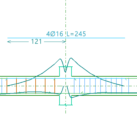
Join
The "Join" option allows you to combine multiple reinforcement bundles of the same type and face into a single one.You must specify the number of bars that will form the new bundle.
The program will take the diameter from the first selected bundle.
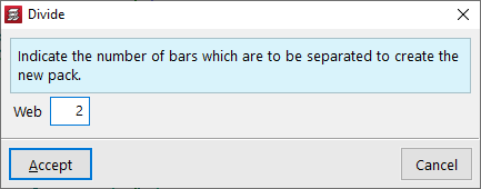
Divide pack
The "Divide pack" option allows a reinforcement bundle containing at least two bars to be divided into multiple bundles, enabling independent editing.
You must specify how many bars will be separated to form the new pack.
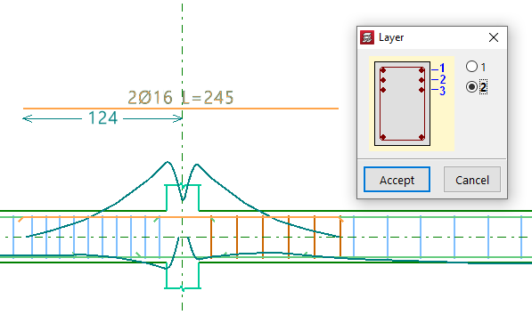
Place in another layer
The "Place in another layer" option allows you to select one or more reinforcement bundles and, after right-clicking, specify the layer where they will be placed.
These changes are evident in the beam's cross section. The program also considers the reduced lever arm in design checks when these changes are made.
Edit
The "Edit" option allows direct modification of reinforcement bars displayed in the main viewer after calculation.
Editing assembly reinforcement
Clicking on the assembly reinforcement lets you adjust the number of bars and select their diameter for both the "Top" and "Bottom" layers.
You can also modify the "Transverse" reinforcement by clicking the corresponding button. In the resulting window, you can edit the Type of stirrup or "Type of branch", add stirrups or branches of different types by clicking on the longitudinal bars in the graphic, or "Delete reinforcement".

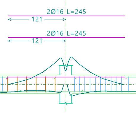
Editing additional reinforcement
To edit additional reinforcement, click on the descriptive labels of the bars in the main viewer. You can modify the number and diameter of bars, their Length, and the Distance between them, as well as the length and type of "Bend" if an end is selected.
When hovering near a bar’s end, a double arrow appears. Clicking it allows you to lengthen or shorten the bar. The program displays the bar’s total length on screen during this adjustment.
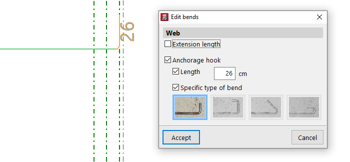
Edit bends
The "Edit bends" option allows you to modify bar hooks. All bends in the frame can be selected by drawing a selection box over it.
You can set the "Length" and select a "Specific type of bend" from the following:
- 90º bend
- 90º bend with horizontal extension
- 135º bend
- 180º bend
Delete
To delete reinforcement, use the "Delete" option and click on the reinforcement to remove it.
Verification, checks and saving changes

After making any reinforcement modifications, click the "Update error information" option in the top toolbar to verify the frame after the changes.
Once this is done, you can use the "U.L.S. and S.L.S. checks at the worst case point" and "U.L.S. and S.L.S. checks at a point" options to view the check reports and examine the results of your changes.
Finally, you can "Save" your work on the frame using the corresponding option.
If you want to exit the editor without keeping the changes, you can close the editing window and confirm in the dialogue box that appears.
Editing transverse reinforcement in beams
The following describes the options available in the beam editor for viewing or editing the transverse reinforcement in beams.
Editing the layout of the transverse reinforcement
To view the layout of the beam’s transverse reinforcement as determined by the analysis, open the editing panel for the entered assembly reinforcement. To do this, open the "Longitudinal reinforcement" menu at the top, select the "Edit" option, and click on the beam’s assembly reinforcement in the main viewport on the right.
| Note: |
|---|
| The "Enter assembly reinforcement" option in the "Longitudinal reinforcement" menu allows you to define the layout of the transverse reinforcement in the same way. |
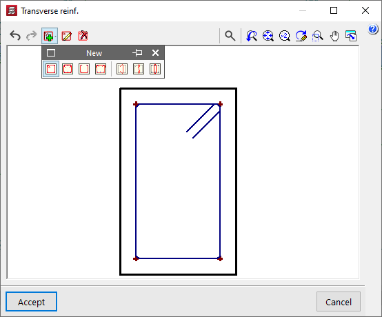
In the window that appears, select the button in the "Transverse" section. From here, using the "Edit reinforcement" option and selecting the stirrups or bars, you can view or modify their type.
The following options are available among the stirrups:
- Closed stirrup
- Closed stirrup with top crosstie overlapping
- Open stirrup
- Open stirrup with top closing crosstie
In the case of branches, the available options include:
- Straight crosstie
- 'S' crosstie
- Closed crosstie
To "Delete frames", click on the option and then on the frames in the viewer.
The "New" option allows you to add new stirrups and branches of the types described. After selecting the stirrup type, click on the starting longitudinal bars and then on the ending longitudinal bars that enclose the transverse reinforcement. In the case of branches, they are added by selecting the longitudinal bars that connect those branches. Once the layout of the transverse reinforcement has been defined, confirm the window.
In the assembly reinforcement editing window, the program also allows you to "Import an admissible arrangement from the assembly reinforcement table" by clicking on the corresponding button on the right-hand side.
Selecting one of the rows in the table defines the longitudinal reinforcement and, in addition, a transverse reinforcement layout with a specific number of stirrups and bars.
Editing the diameter, spacing, number of bars and sections of transverse reinforcement
The remaining editing tools relating to the transverse reinforcement of beams can be found in the "Transverse reinforcement" menu at the top of the "Edit beams" window.
This menu offers the following options:
- Edit template
- Edit reinforcement
- Divide reinforcement spans
- Match reinforcement spans
- Delete reinforcement spans
Each of these options is described below.
Edit template
If an assembly configuration has not yet been defined for the beam, the "Edit template" option allows you to specify the "Number of bars" that will be tied by the stirrup for the span.
Edit reinforcement
The most common approach is to use the "Edit reinforcement" option, which then allows you to select the transverse reinforcement section located at the bottom of the portal section. The program allows you to tick or untick the box "Provide reinforcement in this span" and specify a "Transverse reinforcement arrangement", which can be "The same as for the assembly reinforcement" or "Specific to this interval". In the latter case, it must be defined as described above by clicking the button on the right-hand side.
In either case, once the arrangement of the transverse reinforcement has been defined, the "Diameter of the stirrups", the "Spacing between reinforcement bars" and the "Number of grouped stirrups" are specified, and, if applicable, the "Diameter of the branches" and the "Number of grouped branches".
Divide reinforcement spans
To "Divide reinforcement spans", click on the relevant option and then on the point where you wish to split the stirrup. Next, confirm the "Distance".
| Note: |
|---|
| This option allows you to create areas where stirrups are concentrated or to edit the created reinforcement sections individually, changing the diameter or spacing between the reinforcements within them. |
Match reinforcement spans
The "Match reinforcement sections" option allows you to apply the "Layout", the "Diameters", the "Spacing" or the number of "Grouped hoops and branches" of the selected reinforcement section to any other sections selected subsequently.
Delete reinforcement spans
Finally, the "Delete reinforcement spans" option allows you to delete sections of stirrups, whilst ensuring that at least one stirrup section remains on each beam.
Checking, verifying and saving changes
After making any changes to the reinforcement, click on the "Update error information" option in the top toolbar to check the frame following the changes made.
After selecting this option, you can use the "U.L.S. and S.L.S. checks at the worst case point" and "U.L.S. and S.L.S. checks at a point" options to access the check lists and review the results of the changes.
Finally, you can "Save" the results of your work on the portal using the relevant option. If you wish to exit the editor without saving your changes, you can close the editing window and confirm this in the dialogue box that appears.