
Options in the "Column input" tab
In the "Column input" tab of CYPECAD, which you can access from the bottom of the main interface, you define the storey structure and storey groups of the model and then enter columns, shear walls and wall starts. You can also define setting-out lines to assist with the input of these elements.
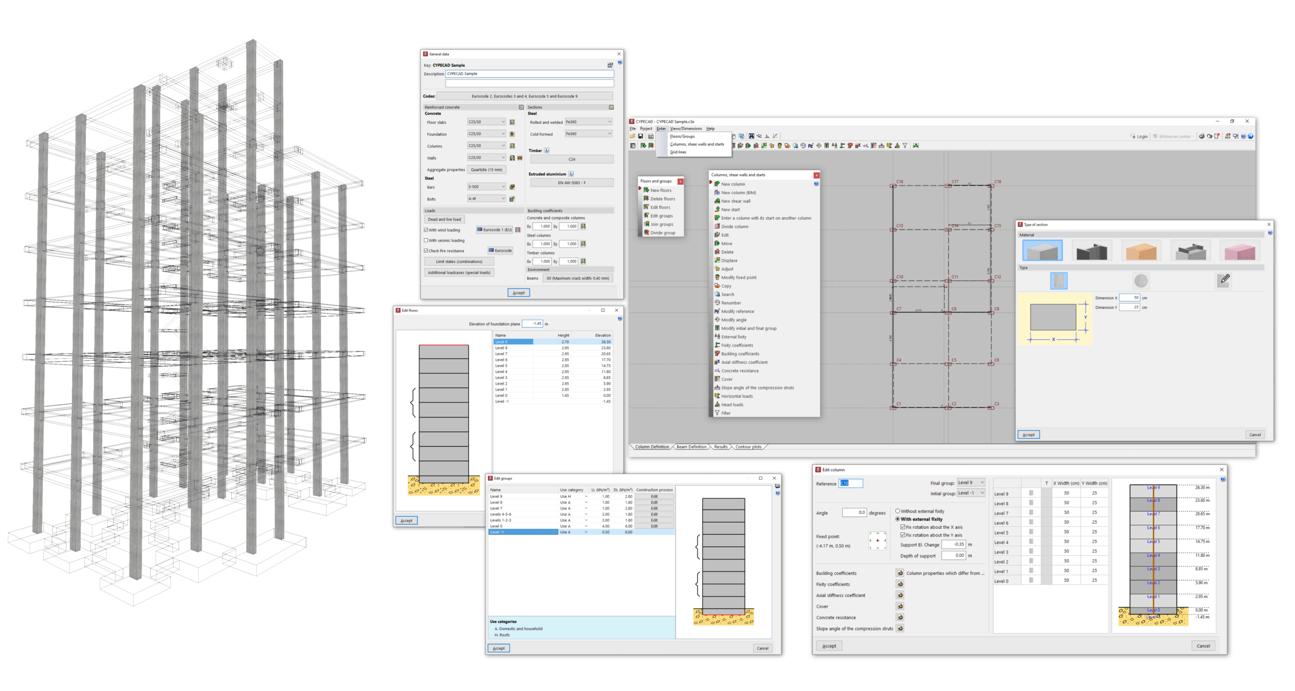
The main features available in this tab include the following:
- In the "Project" menu, you can access the general project data, which allow you to control the codes and materials used, the load cases and load combinations considered in the analysis, and the detailed configuration of checking and sizing options for the different elements, as well as the management of reinforcement tables.
- In the "Input" menu, you can:
- Enter and edit storeys and storey groups, including control of their height and the surface loads applied to them.
- Enter and edit columns, core walls and starters, including modification of their geometry, section, layout and properties (such as fixity, buckling and axial stiffness coefficients, concrete strength value, cover, etc.), as well as the application of horizontal loads and head loads to these elements.
- Define the reference point for the setting-out origin and enter horizontal and vertical setting-out lines.
- In the "Views/Dimensions" menu, you can modify the dimensions between the elements entered in this tab and control their display.
Once you have completed the work in the "Column input" tab, the rest of the structure is entered in the "Beam input" tab. This includes beams, slabs, walls, foundations and special elements such as ramps, stairs and integrated 3D structures.
Inserting floors and groups
The definition of floors and groups in the program is necessary for the subsequent insertion of elements such as columns, screens or walls from floor to floor, or beams and floor slabs on each floor.
To enter floors and groups in CYPECAD, within the "Column input" tab, open the "Input" menu and select the "Floors/Groups" option.
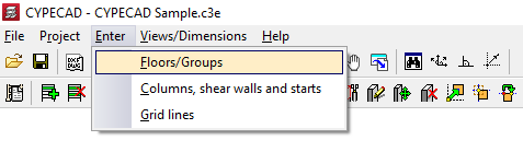
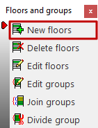
This opens a menu that includes the following option:
- New floors
This feature is detailed below.
New floors
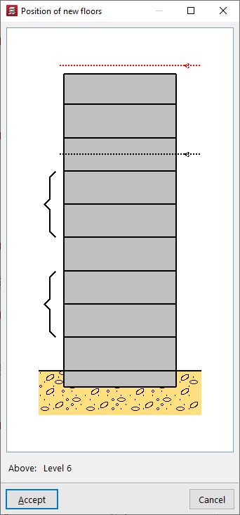
When clicking on the "New floors" option, if other floors have been entered previously, the "Position of new floors" must be indicated in relation to the existing ones by clicking on the desired position in the diagram.
If no other floors have been entered previously, the program will skip to the next step.
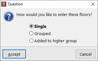
Now, a dialogue box appears asking how you want to enter the sloors, either "Single" or "Grouped".
If floors have been entered previously, they can also be grouped with the floors below or above using the options "Grouped below" or "Grouped above", which will be available in this case.
Entering single floors
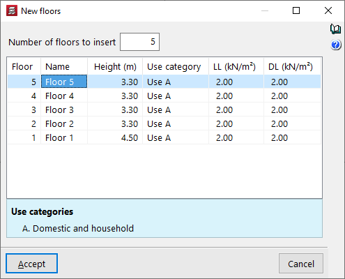
When entering "Single" floors, in the window that appears next, "New floors", first enter the "Number of floors to insert" to generate the same number of rows in the table.
Each row represents a "Floor", with its "Name", "Height" (distance between the upper faces of the slabs), the "Use category" of the live load associated with the floor, the numerical value of this live load (column "LL") and the numerical value of the dead loads (column "DL").
The surface load indicated here (both live load and dead load) will be automatically applied to the surface of all structural elements drawn on each floor, such as beams and slabs.
| Note: |
|---|
| It is not necessary to add the weight of the structure itself, as this is automatically taken into account by the program. |
Entering grouped floors
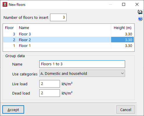
When entering grouped plants, the programme allows you to define the "Number of plants to insert" in the "New plants" window. This automatically adds rows to the central table. Here you can define the "Name" and "Height" of each plant in the group.
At the bottom, you can enter the "Group data". To do this, enter the "Name" of the group, select one of the available "Categories of use" and enter the numerical values for the "Live loads" and the "Dead loads".
The live load and dead loads defined here will apply to all floors in the group.
| Note: |
|---|
| Groups are sets of consecutive floors that are identical to each other and have a single output of results. Data entry will be the same for all floors in the group. After the analysis, the envelope results for all floors will be displayed. The design and reinforcement will be unique, allowing the output of a single valid plan for all groups. |
Editing drawings and groups
To access the floor and group editing tools in CYPECAD, within the "Column input" tab, open the "Enter" menu and select the "Floors/Groups" option.
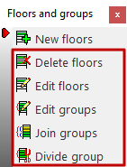
This allows you to access a menu that includes the following options:
- New floors
- Delete floors
- Edit floors
- Join floors
- Divide floors
Each of these features is detailed below.
Delete floors
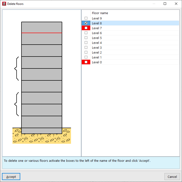
To "Delete floors", select the option, tick the boxes corresponding to the floors you wish to delete, and confirm.
| Note: |
|---|
| It is not possible to directly delete the floors marked in red, as they coincide with the start or end floor of a wall. In this case, you must edit the wall from the "Beam input" tab in order to subsequently delete the floor. |
Edit floors
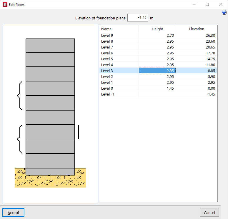
The "Edit floors" option allows you to modify their "Height" and consult the absolute "Elevation" above ground level. The floor height being modified is represented as a linear elevation between floors in the attached diagram.
The "Foundation level" is also modified in this window. The value indicated here will be used to define the level of the first group: if it is negative, the building will have a buried part. This will be shown in the attached diagram through the representation of the terrain.
| Note: |
|---|
| The program will not generate wind action (if this option is activated in "General data") on groups located below ground level. |
Edit group
The "Edit groups" option allows you to modify the "Name" of each group, as well as define the "Use category" associated with it, and enter the numerical value of the live loads and dead loads that apply to the floors in the group.
In the attached diagram, the program shows the floors belonging to each group in square brackets. The floors in the selected group will be coloured red.
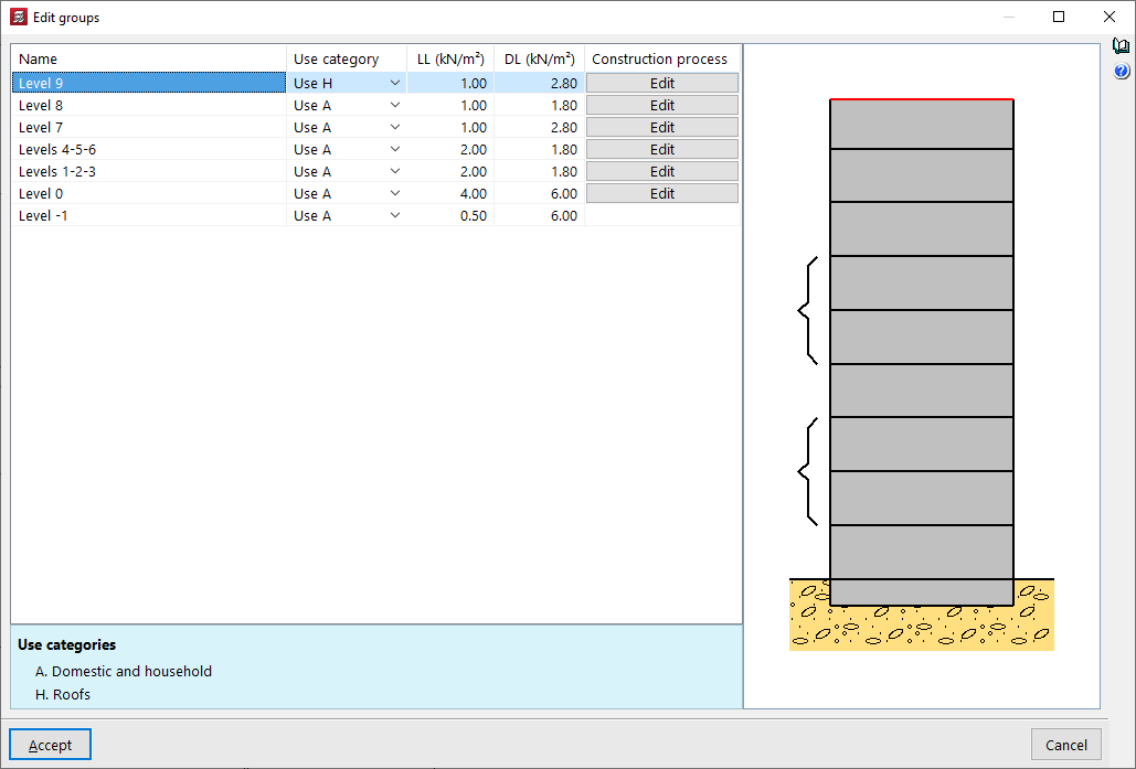
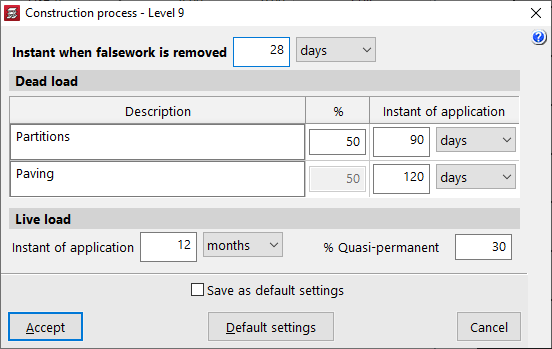
Additionally, the program allows you to "Edit" the "Construction process" for each of the groups.
You can modify the "Instant of falsework is removed" and the "Instant of application" of the "Dead loads" (e.g., partition walls and flooring) and the "Overload" of use, also indicating the percentage of overload considered quasi-permanent (% Quasi-permanent).
These options are used to adjust the analysis of the deflection of the structural elements.
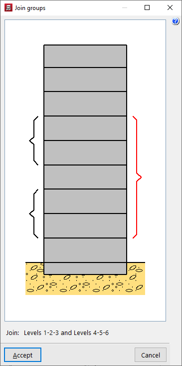
Join groups
The "Join groups" option allows you to merge adjacent plant groups. When selecting multiple plants, the program will ask which group's beam and load information you wish to retain.
| Note: |
|---|
| In general, it is not recommended to group more than three or four floors to avoid oversimplification. For this reason, the program allows for the grouping of up to five consecutive floors. |
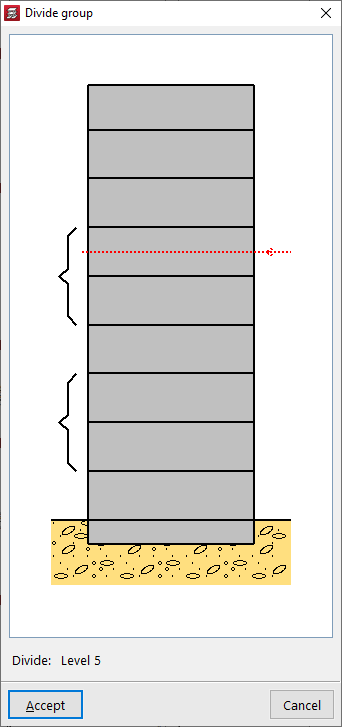
Divide groups
The "Divide groups" option allows you to perform the opposite action to merging: the program will split the selected group and generate several groups separated by the line entered in the graph.
Entering columns
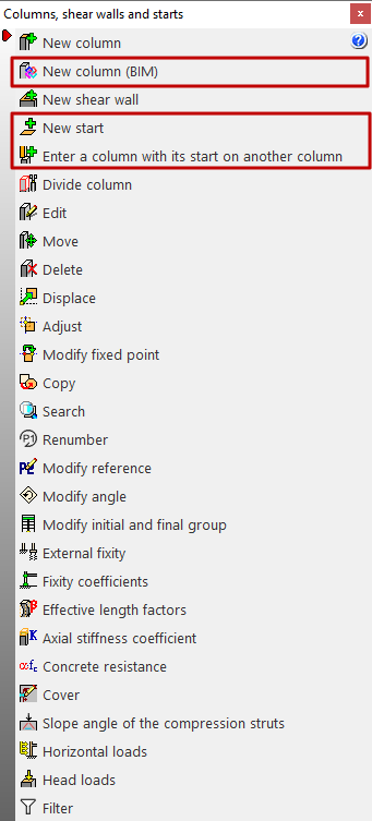
To enter columns in CYPECAD, within the "Column entry" tab, open the "Enter" menu and select the "Columns, shear walls and starts" option.
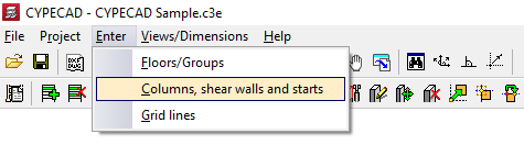
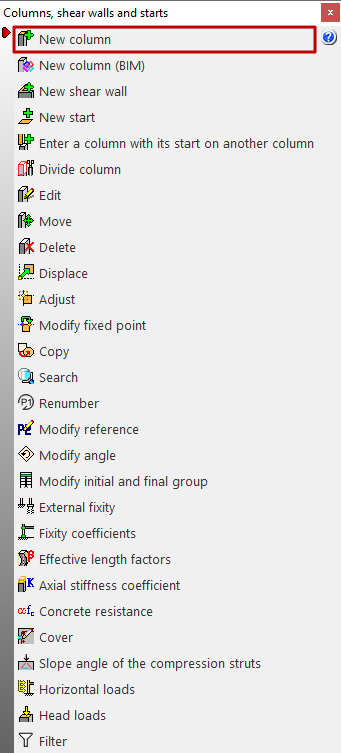
This opens a menu with the following options:
- New column
- New column (BIM)
- New shear wall
- New start
- Enter a column with its start on another column
- Divide column
- Edit
- Move
- Delete
- Displace
- Adjust
- Modify fixed point
- Copy
- Search
- Renumber
- Modify reference
- Modify angle
- Modify initial and final group
- External fixity
- Fixity coefficients
- Effective length factors
- Axial stiffness coefficient
- Concrete resistance
- Cover
- Slope angle of the compression struts
- Horizontal loads
- Head loads
- Filter
The first of these features is detailed below.
New column
The "New column" option allows you to insert a column. The model must have more than one floor or group of floors for this option to be visible, as columns in the program must start and end in two different groups of floors.
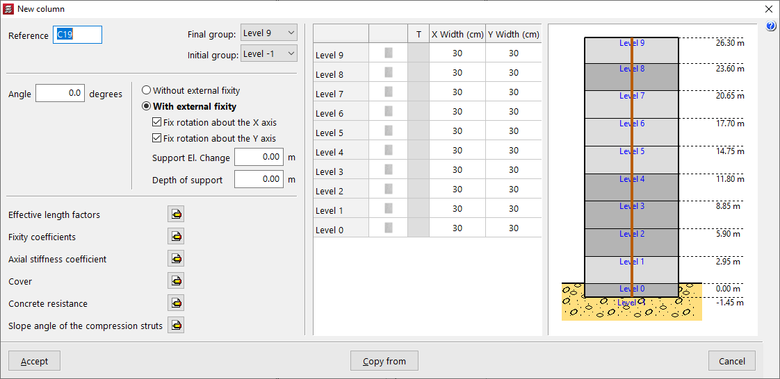
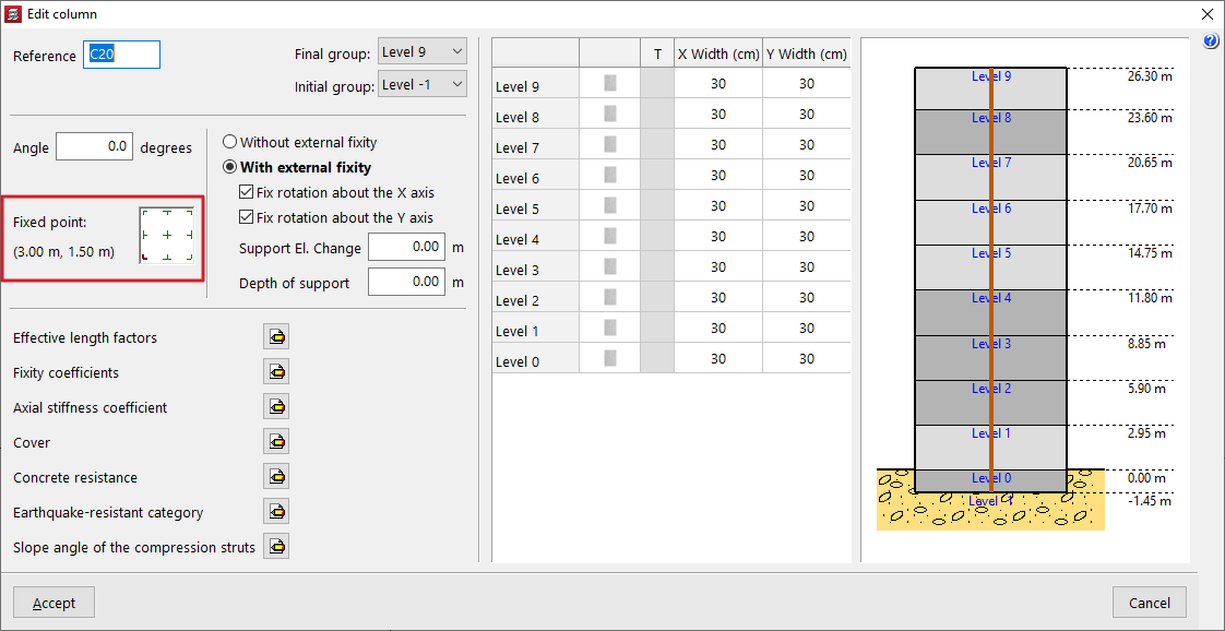
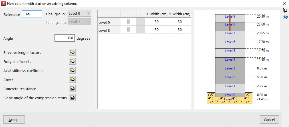
After selecting the option, the "Reference" of the column is entered and the "Final group" and "Initial group" are defined using the drop-down lists. The diagram on the right-hand side can help to visualise the floors of the model and the position of the column being inserted with respect to them.
An "Angle" can also be applied, which will rotate the column in plan.
"With external fixity" must be selected if the column starts on a pad footing or a pile cap, and "Without external fixity" if the column starts on a mat foundation, a foundation beam, a wall, or if it is supported on a beam or slab of the structure.
Optionally, the "Fix rotation about the X axis" and "Fix rotation about the Y axis" checkboxes can be deactivated so that rotation in that direction is not restrained. In this case, the beams in contact with the base of the column will contribute to centring the loads.
In "Support elevation change", a positive or negative value can be entered to modify the position of the base of the column with respect to the level of the group from which it starts.
The value of the "Depth of support" is used to indicate the depth of the foundation, which allows the program to correctly measure and draw the reinforcement of the column starters. If pad footings or pile caps are inserted in the program, it is not necessary to change this value, and it can be left as 0.
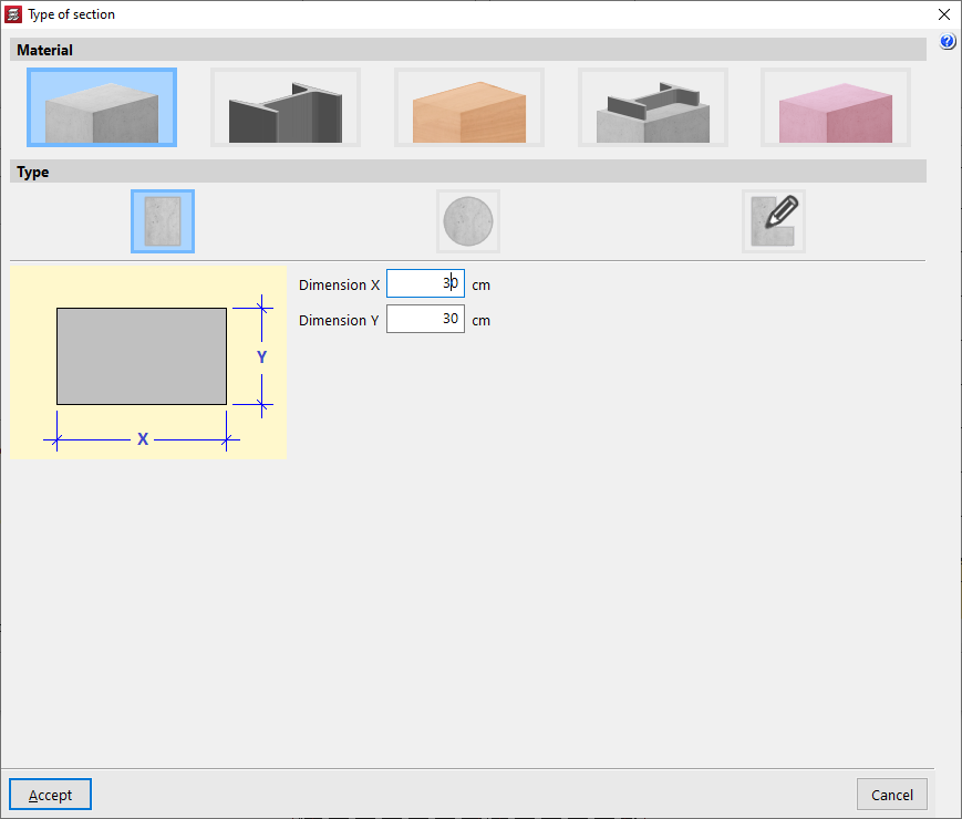
Column section
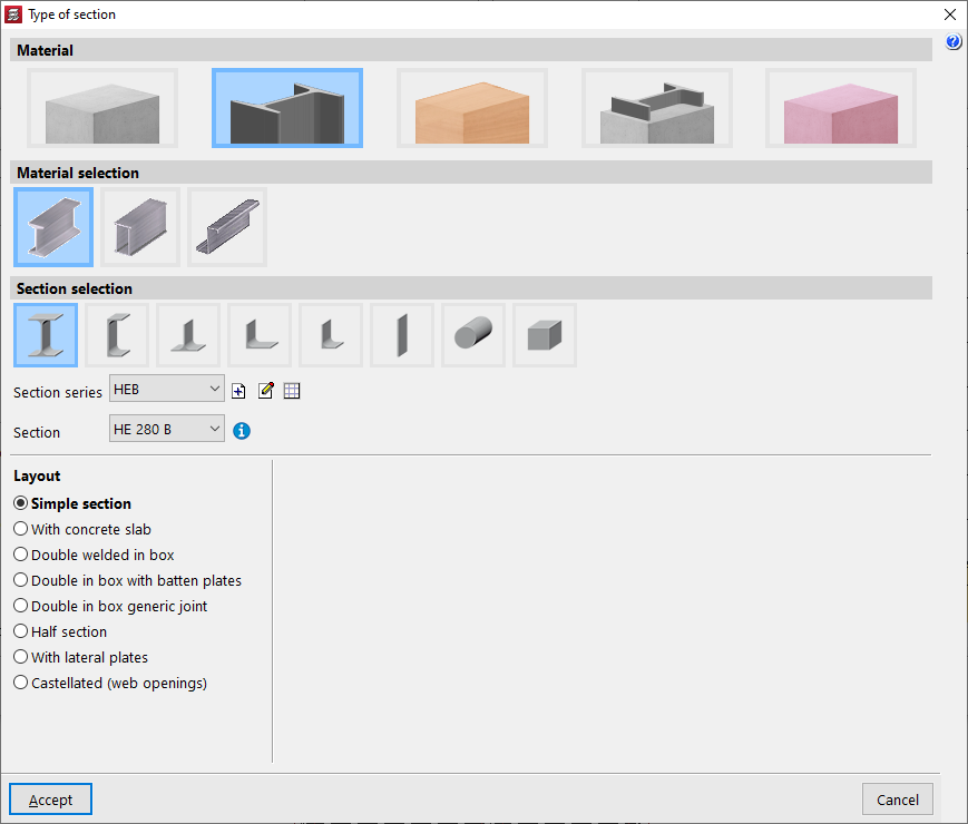
In the table on the right, the section of each column section is defined, floor by floor. To modify the "Section type", click on the buttons available in the second column. In the "Material" section, you can choose whether the column is "Reinforced concrete", "Steel", "Timber" or "Composite section". You can also define a column with generic material and section ("Generic").
In the case of steel columns, after accepting, you can activate the transposed steel section box (columns "T") to swap the axes of the section and thus rotate the column in plan.
In the case of rectangular concrete columns, the columns "Width X" and "Width Y" allow you to quickly modify these parameters.
Column parameters
In the lower left corner, you can modify the following parameters if desired:
- Effective length factors
- Fixity coefficients
- Axial stiffness coefficient
- Cover
- Concrete resistance
- Earthquake-resistant category
- Slope angle of the compression struts
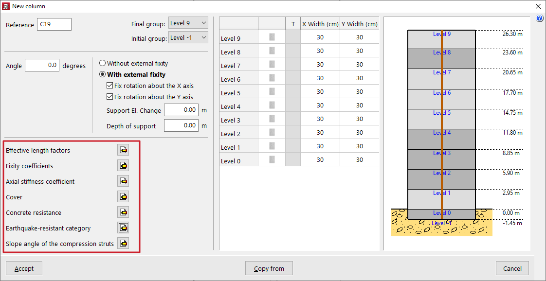
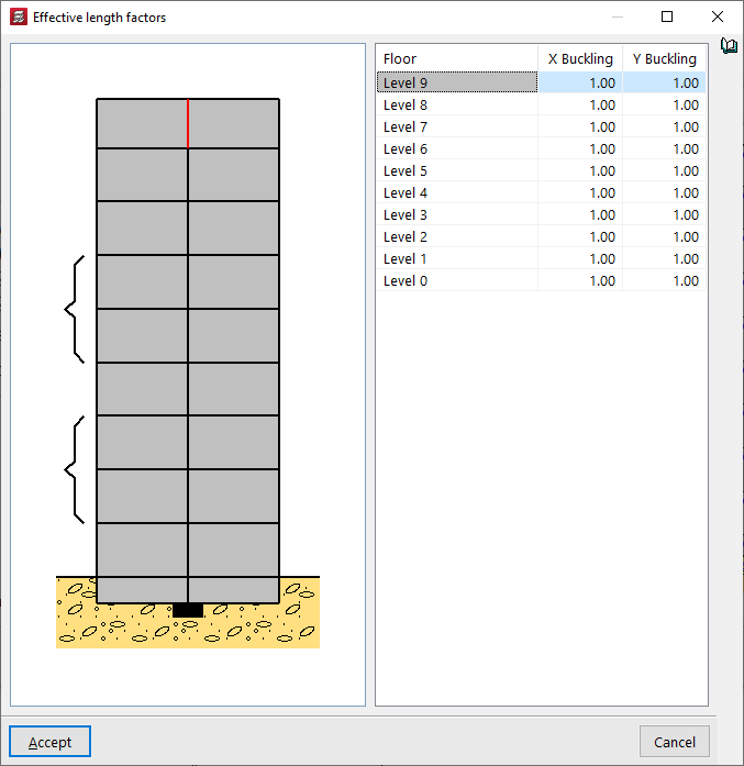
Effective length factors
By default, the value of the "Effective length factors" is 1 in both directions. It is possible to increase or decrease the "X Buckling" and "Y Buckling" coefficients by entering the desired value in the corresponding cell.
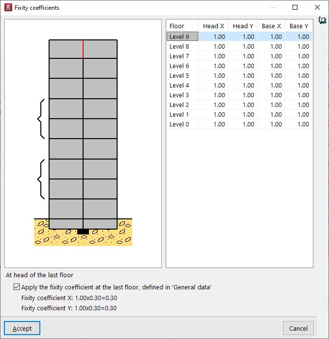
Fixity coefficients
The value of the "Embedding coefficients" is 1 by default, but it can be reduced to decrease the embedding or simulate a joint, both at the head and foot of each section of the column and in both directions of space, X and Y.
If the "Apply the embedding coefficient on the top floor, defined in "'General data'" box at the bottom remains active, the embedding coefficient in X and Y of the head of the upper section of the column indicated in the table will be multiplied by this value, which by default is equal to 0.30.
| Note: |
|---|
| This coefficient is defined in "Project" > "General data" > "By position" > "Options for columns, shear walls, walls and corbels" > "Forces" > "Fixity coefficient on top floor". |
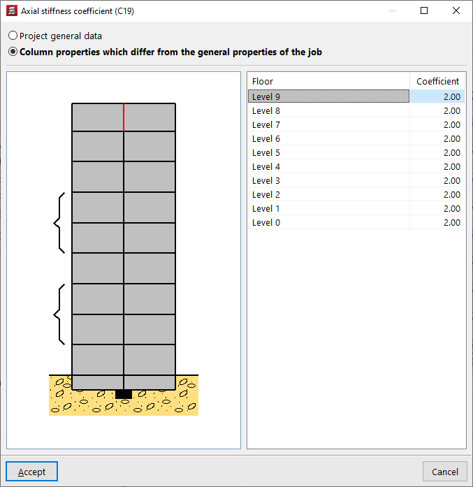
Axial stiffness coefficient
The "Axial stiffness coefficient" can be defined in the "Project general data" (from "Project" > "General data" > "By position" > "Options for columns, shear walls, walls and corbels" > "Forces"), with a default value of 2.
You can also select the "Column properties which differ from the general properties of the job" option to modify it floor by floor.
Increasing the value of the axial stiffness coefficient reduces the shortening of the columns in the analysis.
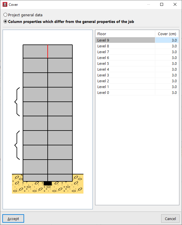
Cover
You can edit the "Cover" of the column so that it takes the value defined in the "General project data" ("Project" > "General data" > "By position" > "Common options for bars" > "Covers") or indicate "Column properties which differ from the general properties of the job". In this way, the cover value is entered for each floor.
The cover is defined as the distance from the outer face of the column to the nearest face of the stirrup bar.
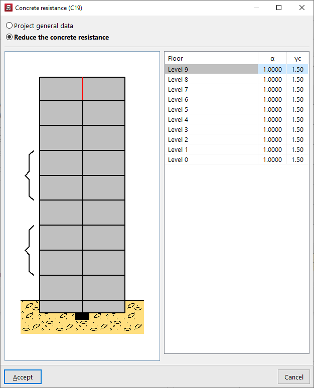
Concrete resistance
The "Concrete resistance" can be taken from the values defined in the "Project general data" or, if "Reduce the concrete resistance" is indicated, it is defined by the following parameters on each floor:
- the concrete resistance reduction factor (α);
- and the concrete strength reduction factor (γc).
Earthquake-resistant category
If seismic analysis is enabled for the project ("Project" > "General data" > "With seismic action"), it is also possible to change the "Earthquake-resistant category" for each section of the column to "Primary", "Secondary" or "Wall edge reinforcement".

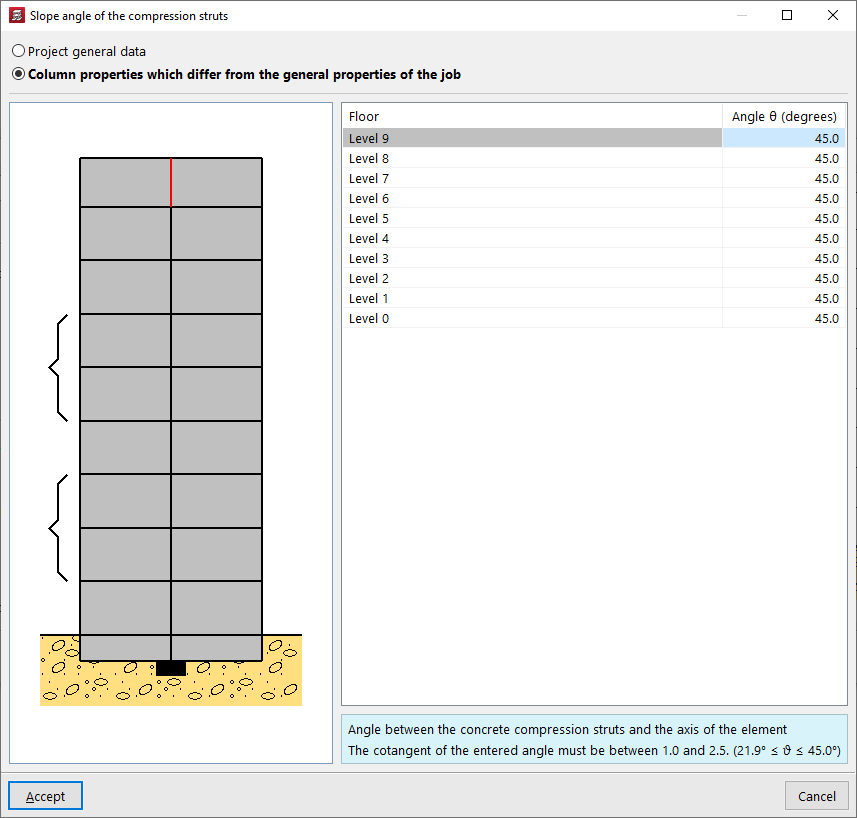
Slope angle of the compression struts
The slope angle θ of the concrete compression struts with respect to the axis of the element can be defined in the "Project general data" or modified for each column section from floor to floor if "Column characteristics which differ from general properties of the job" is selected. The cotangent of this angle must be between 0.5 and 2.
| Note: |
|---|
| All the values that define the column can be obtained from another column in the project by clicking on the "Copy from" option and then selecting a column that has already been entered and has all the information defined. |
Layout of the column on the floor plan and definition of the fixed point
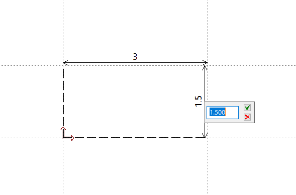
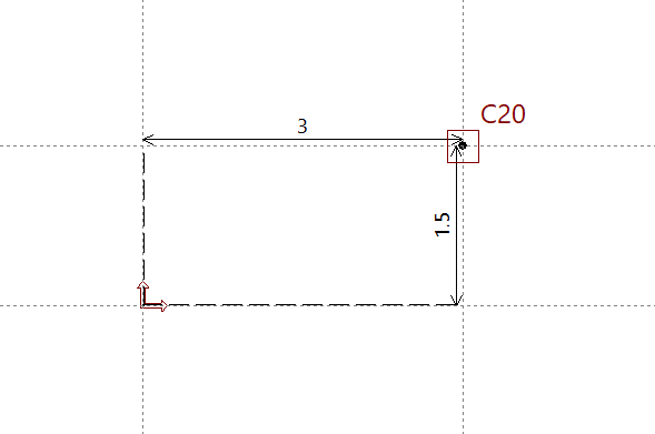
After accepting the characteristics definition window, the column is inserted into the floor plan. If you click anywhere in the space, its position is indicated by entering the X and Y coordinates relative to the reference point.
To position the column, you can also use the "Template snaps" and/or "Layout lines" previously entered in the model.
The position of the pointer when clicking while capturing a point influences the definition of the fixed point of the column, or point common to all floors from which the growth of the column section is determined. This fixed point can be centred in the column section or located at the edges or corners of the column.
At any time, using the "Edit" option in the "Insertion" > "Column, shear walls and starts" menu, you can consult the definition of the"Fixed point" of the column entered and modify it if necessary. You can also change the other parameters used in the column definition.
Inserting columns (BIM), starts and columns with a start on another column
The following options related to entering columns and footings in CYPECAD are found in the "Column input" tab, by opening the "Enter" menu and selecting the "Columns, shear walls and starts" option.
This opens a menu that includes the following options:
- New column (BIM)
- New start
- Enter a column with its start on another column
Each of these features is explained below:
New column (BIM)
The "New column (BIM)" option allows CYPECAD columns to be entered by selecting columns defined in a BIM model created with another program, which have been imported after a linking process to BIMserver.center.
| Note: |
|---|
| Among the CYPE programs capable of modelling and exporting columns to the BIM model are CYPE Architecture and IFC Builder. |

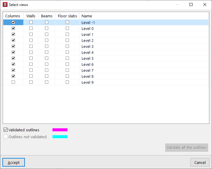
The outlines of the column from the BIM model are visible if, in the "View selection" table (accessible from the "Edit views" button at the top left), the boxes in the "Columns" column and the "Validated outlines" and/or "Unvalidated outlines" options at the bottom are kept activated.
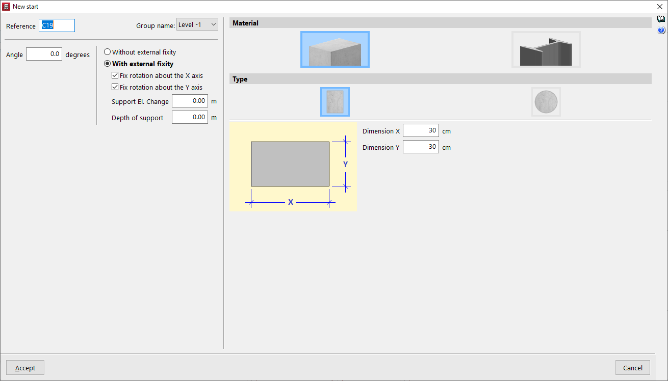
New start
For the program, a start is a point representing the base of a column where it is possible to apply point loads or insert a foundation element without having to draw or analyse the entire column.
The "New start" option allows these elements to be entered. When defining them, you only need to specify the "Group name" where they will be entered, as well as the "Reference", the "Angle" and whether or not they have an external link, as well as the "Material" of the section from among those available.
Enter a column with its start on another column
The "Enter a column with start on an existing column" option allows you to click on an existing column that does not reach the last group and, from there, define a different column with other parameters.
The options available in the pop-up window are similar to those that appear when using the "New column" option.
Inserting horizontal loads on columns
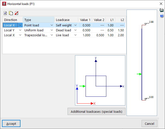
The "Horizontal loads" option, available in the "Enter" menu and under "Columns, shear walls and starts", in the "Column input" tab, allows horizontal loads (point, uniform or trapezoidal) to be applied to columns.
After clicking the option, a column must then be selected. The "Horizontal loads" window will open.
On the right-hand side, an elevation diagram of the column is shown with its initial and final levels. At the bottom, the column cross-section is displayed, together with the global axes of the project and the local axes of the column. The local axes of the column will coincide with the global axes when the column has a zero rotation angle.
In the table at the top, horizontal loads applied to the column segments can be "Added", "Copied" and/or "Deleted". Each row in the table represents a horizontal load applied to the column. For each load, the following parameters are defined:
- Direction
Allows you to select the direction of the horizontal load, either "X Local", "Y Local", "X General" or "Y General". The direction of the load is given by its positive or negative sign. - Type
Allows you to select the type of horizontal load between "Point", "Uniform" or "Trapezoidal". - Loadcase
Allows you to select the loadcase where the horizontal load will act. - Value 1 / Value 2
These parameters allow you to enter the value of the horizontal load with its sign:- If the load is of the "Point" type, only "Value 1" needs to be entered, and the units are force.
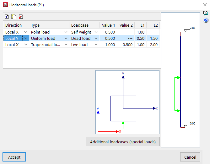
- If the load is of the "Uniform" type, only "Value 1" needs to be entered, which will be applied to the column between the distances defined in "L1" and "L2", and the units are force per unit length.
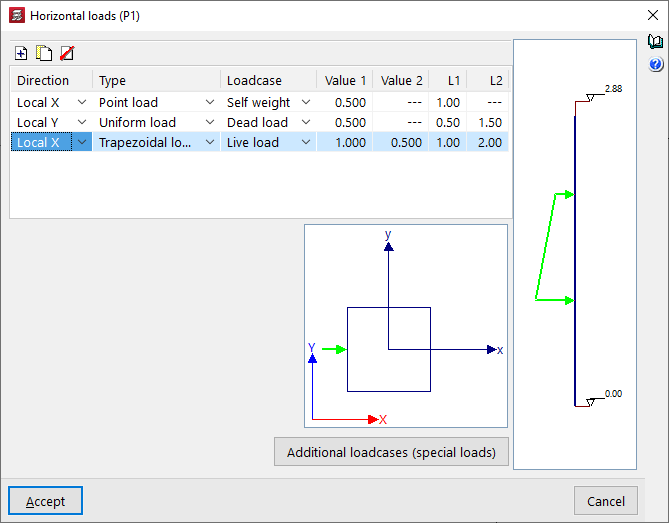
- If the load is of the "Trapezoidal" type, you will need to enter "Value 1" and "Value 2", which will be applied at the distances defined in "L1" and "L2". Between these distances, the load value is interpolated linearly. The units are force per unit length.
- L1 / L2
These parameters define the distance at which the horizontal load is applied:- In the case of a point load, the "L1" value corresponds to the distance between the point of application of the load and the starting point of the column at its bottom.
- In the case of a uniform load or a trapezoidal load, the "L1" value corresponds to the distance between the point of application of the load and the bottom of the column, while the "L2" value corresponds to the distance between the end point of application of the load and the bottom of the column.
The horizontal load selected in the table will be represented both in the elevation diagram on the right and in the section diagram at the bottom.
The "Additional loadcases (special loads)" button at the bottom allows direct access to the panel for creating and editing the loadcases for the structure.
Inserting loads at the head of columns
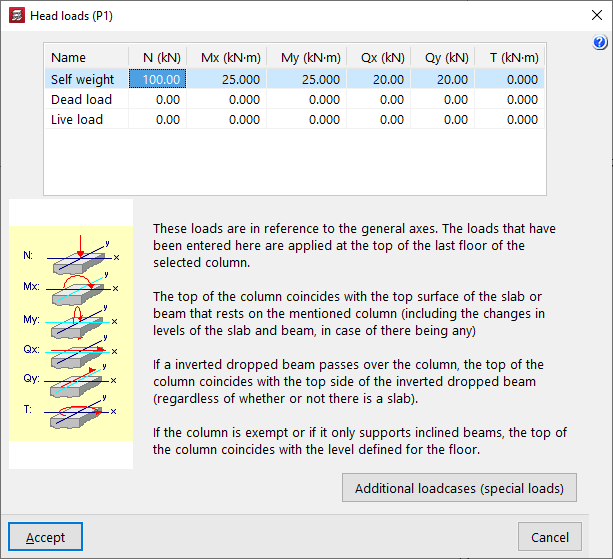
The "Head loads" option, available in the "Input" and "Columns, shear walls and starts" menus, in the "Column input" tab, allows you to enter loads (axial, moments, shear and torsional) both at the column bases and at the column heads on the top floor.
After clicking on the option, you must then select a start or a column. This opens the "Head loads" window.
This window displays a list at the top where you can define the loads to be applied to the base or top of the column for each of the available loadcases and in the specified units. The different columns allow you to enter the axial force ("N"), the bending moments ("Mx", "My") and shear forces ("Qx", "Qy") in both directions, and the torsional moment ("T").
The "Additional loadcases (special loads)" button at the bottom allows direct access to the panel for creating and editing the loadcases for the structure.
The loads refer to general axes of the structure, and the sign criteria are those indicated in the legend visible on the left side of the window.
| Note: |
|---|
| The loads defined here are applied at the head of the top floor of the selected column. The head of the column coincides with the upper face of the floor slab or beam that rests on that column, including any unevenness in the floor slab and beam, if any. If an inverted hanging beam passes through the column, the column head coincides with the upper face of the inverted hanging beam, regardless of whether there is a floor slab or not. If the column is free-standing or if only inclined beams rest on it, the top of the column coincides with the defined floor level. |
Table of contents
Complete your tour of CYPECAD by exploring the other available sections:
- Introduction
- Introduction and creating new jobs
- General data configuration
- Defining floors and groups of floors and inserting columns, shear walls and starts ("Column input" tab)
- Inserting beams, walls, floor slabs, foundation elements and special elements, and structural analysis (the "Beam Input" tab):
- Checking analysis results and editing elements (the "Results" tab):
- Options on the "Contour plots" tab
- Printing documents and exporting data
- More information:
- General features of CYPECAD