Selection and editing of reinforced concrete piles
The selection and editing of reinforced concrete piles is carried out by entering a new foundation element of the "Pile" type or by editing an existing pile with reinforced concrete piles, using the "Piles" option in the editing window.
General definition
By selecting "Reinforced concrete pile" in the pile cap entry or editing window, it is possible to specify the characteristics of each pile, in addition to the ground data and other calculation parameters.
This option can analyse, verify and design piles as reinforced concrete elements, in addition to the analysis of the pile cap.
- From the "Pile" drop-down menu, pile types are created and selected with data on their geometry, material, section and reinforcement.
- The "Length (Lt)" refers to the length of the pile under the pile cap.
- "Penetration (Lp)" indicates the length of the pile that penetrates the pile cap. It is recommended to enter a value between 10 and 15 centimetres.
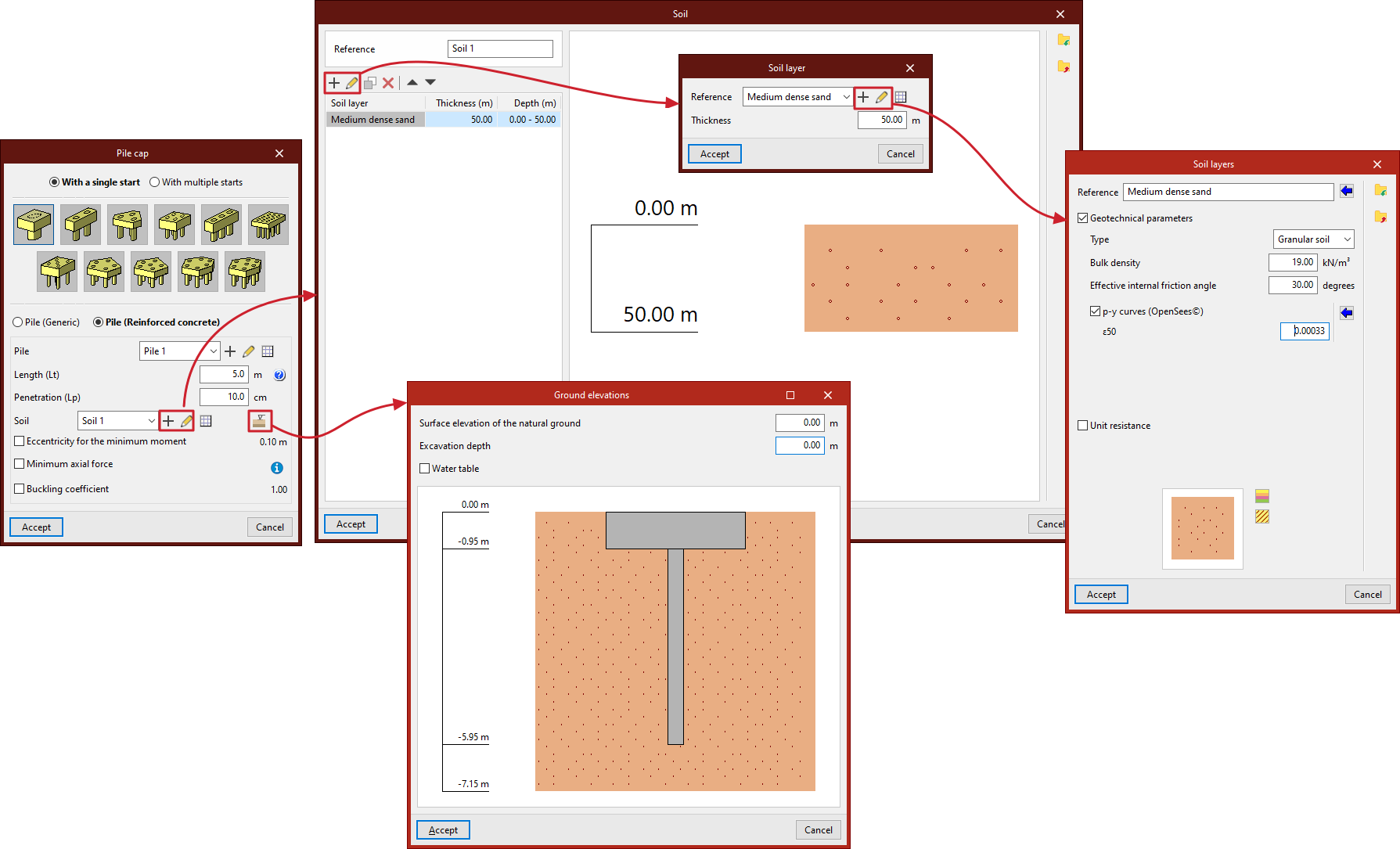
- Next, you must configure the "Terrain", which you can create, edit and save in a list of terrains using the tools on the right.
- The "Terrain elevations" option allows you to define the "Elevation of the natural terrain surface", the "Excavation depth" based on the previous one, and the elevation of the "Water table".
- Finally, by ticking the corresponding boxes, you can indicate the "Eccentricity for minimum moment", the "Minimum axial force" (based on a coefficient that multiplies its "Axial force") and the "Buckling coefficient".
- Where applicable, the "Spacing between pile axes" is also indicated and, if rectangular or linear pile caps have been selected, the "Number of piles".
- The "Pile displacement" option appears in some types of pile caps and allows you to apply an "X displacement" and a "Y displacement" to each of the piles in order to make small adjustments to their position.
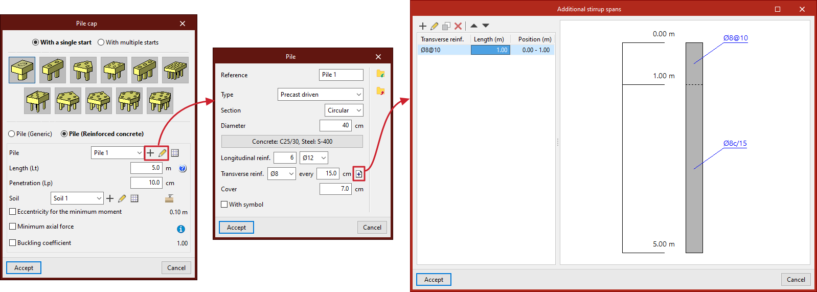
Pile selection
In the "Pile" drop-down menu, when you click on "New" or "Edit selected type", you define:
- the "Reference" of the pile;
- the "Type" of pile ("Prefabricated driven" or "Cast in situ");
- its "Section" ("Circular" or "Square");
- its "Diameter" or "Width", depending on whether the pile section is circular or square;
- the "Materials" of the pile, including the "Concrete" and "Steel" of its reinforcement;
- its "Longitudinal reinforcement", which can be defined in "Corners" and for "Face X / Face Y") in square section piles;
- its "Transverse reinforcement" throughout the pile by default, with the option to define "Additional abutment sections" by clicking on the button on the right:
- each additional abutment section indicates the "Length" and "Transverse reinforcement" arranged in that section, which will replace the default transverse reinforcement; the additional transverse reinforcement sections defined will be arranged with respect to the pile head and will be represented in the plans of the foundation element, both in the pile section and in the attached information table;
- the concrete "Cover" over the reinforcement;
- and the symbol used for the pile (by activating the "With symbol" checkbox).
The information entered for each pile type can be viewed in a list of types and copied, edited or exported to files on disk using the corresponding options to be used in other models.
Definition of the ground
Each ground is defined by its "Reference" and several layers or strata that compose it:
In each "Stratum" you must define its "Reference", its "Thickness" and its characteristics, including the following:
- Geotechnical parameters (optional)
- Type (Cohesive soil / Granular soil / Rock)
- Apparent density
- Simple compressive strength
- Effective internal friction angle
- Internal friction angle
- p-y curves (OpenSees©)
- ε50
- J
- Unit resistances (optional)
- Tip
- Shaft
In the diagram below, the "Colour selection" and "Pattern selection" are made for the representation of the stratum in the terrain section provided by the program.
The information entered for each stratum can be consulted in a list of types and copied, edited or exported to files on disk using the corresponding options to be used in other models.
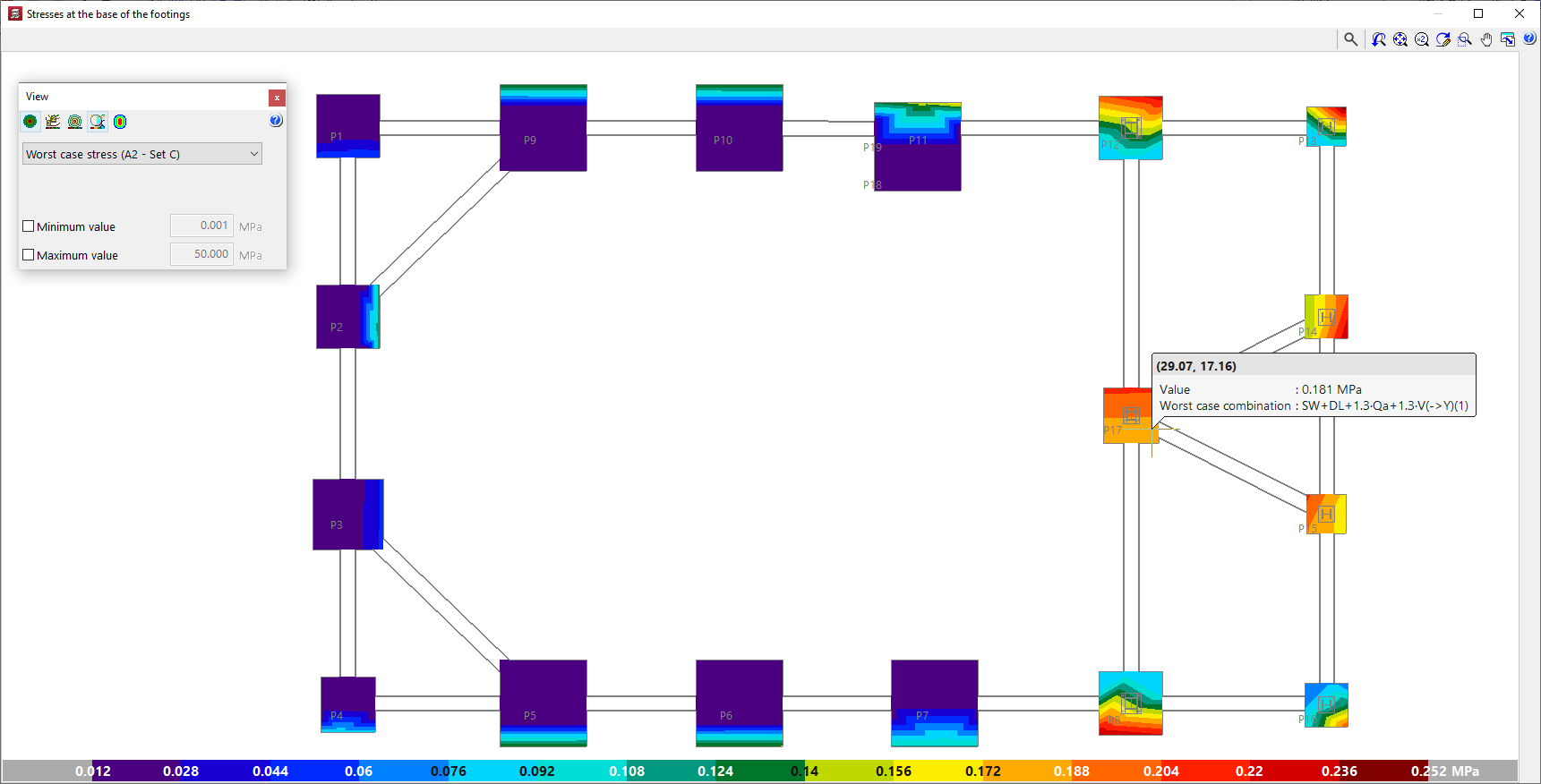
Diagrams of soil pressure in footings
The soil pressure diagrams at the base of the footings can be consulted in CYPECAD and CYPE 3D. This makes it possible to evaluate the suitability of the solution adopted for the foundation, as well as the distribution of loads on the ground and the behaviour of each footing.
- In CYPECAD, the "Stresses at the base of the footings" option can be used to view the stress diagrams at the base of all footings and is located in the "Foundation" menu, visible in the "Beam definition" and "Results" tabs. The stress diagram at the base of each footing can also be accessed through its editing menu (from "Foundations", "Foundation elements", "Edit"), by clicking on the "Stresses" option.
- In CYPE 3D, from the "Foundation" tab, it is also possible to access the stress diagram at the base of each footing through its editing menu (from "Foundation elements", "Edit"), by clicking on the "Stresses" option.
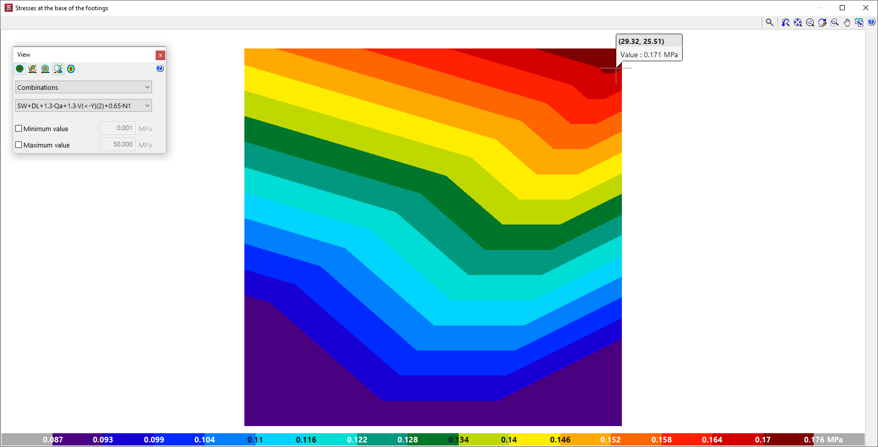
In either case, the program opens a consultation window showing the stress diagrams at the base of the footings with a colour gradient. The colour scale at the bottom acts as a legend and indicates the values represented in the diagram.
This representation is similar to the one used in CYPECAD in the "Contour plots" tab for checking the results of slabs and waffle slabs.
In addition, by hovering the cursor over each point in the diagram, the program displays an information text with the coordinates of the point, the value of the voltage shown at that point and, as the case may be, the combination in which it occurs.
Stress diagram display settings
The floating window is used to adjust the display of the stress diagrams by means of the following options:
- The following options are available at the top:
- The "See contour plots", "See contour lines with values" and "See isolines without values" options can activate the display of the information in the indicated formats.
- Alternatively, users can "Automatically scale when zooming in" so that colours, lines and values displayed on the screen are adjusted according to the visible area when zooming in.
- Optionally, the "Colours for the representation of contour plots" can be modified, including the range and number of colours.
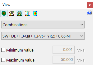
- Worst case / Combinations / Maximum
In this drop-down menu, users select whether the following voltage values are to be displayed or not:- Worst case
Displays the worst-case stress of any combination at each point. At each point, the stress shown may belong to a different combination. - Combinations
Displays the stresses of a particular combination chosen by the user, to be selected in a second drop-down. - Maximum
Displays the results of the combination resulting in the maximum stresses.
- Worst case
- Minimum value / Maximum (optional)
- By activating these boxes and entering a numerical value in the corresponding fields, the minimum and maximum values of the colour gamut range of the representation can be set.