
Inserting foundation elements (footings and pile caps)
Foundation elements can be entered via the “Beam input” and “Results” tabs. The option will be available when you are in a group where a column or wall defined as “With external connection” begins, or a wall with a strip footing or a “Fixity” at its base. To move to the desired group, use the “Move up group”, “Go to group” and “Move down group” options.
To insert a foundation element, open the “Foundation” menu at the top and select the “Foundation elements” option.
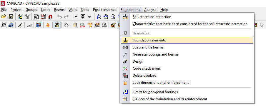
This opens the "Foundation elements" window, which displays the following options:
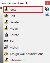
- New
- Edit
- Delete
- Move
- Rotate
- Join
- Match
- Assign wall foundations
- Information
To add a new foundation element, click on "New".
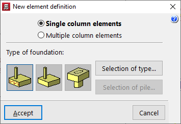
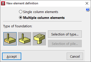
Defining a new foundation element
In the window that appears, you must first select "Single-column elements" if it is an isolated foundation element, or "Multi-column elements" if it is a combined foundation element or one shared by several columns.
In the "Type of foundation" section, choose from the following options:
- Reinforced concrete footing
- Mass concrete footing
- Pile cap
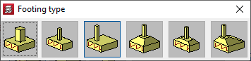
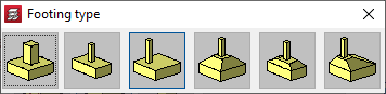
Selecting the type of footing
If you select a reinforced concrete footing or a plain concrete footing, under "Selection of type" you must specify whether it is square, rectangular or pyramidal, and whether it is centred or off-centre:
- Square footing
- Centred rectangular footing
- Eccentric rectangular footing
- Centred rectangular footing
- Tapered centred rectangular footing
- Tapered eccentric rectangular footing
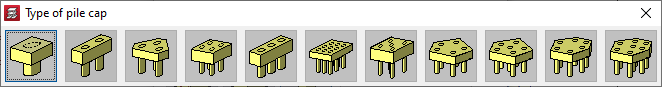
Selecting the type of pile cap
If you select a cluster, the "Selection of type" option allows you to define between one and seven pile caps, in rectangular, pentagonal or hexagonal shapes, as well as to use linear or rectangular clusters with a number of pile caps to be specified along the X and Y axes.
- Pile cap for 1 pile
- Pile cap for 2 piles
- Pile cap for 3 piles
- Pile cap for 4 piles
- Strip pile cap
- Rectangular pile cap
- Rectangular pile cap for 5 piles
- Pentagonal pile cap for 5 piles
- Pentagonal pile cap for 6 piles
- Pentagonal pile cap for 6 piles
- Hexagonal pile cap for 7 piles
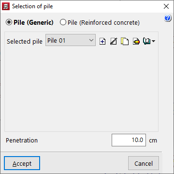
Selecting piles
If you select a pile cap, after clicking "Select pile", you can choose either a generic pile or a reinforced concrete pile:
- Generic pile
In this case, the general characteristics of the piles will be defined solely for the purpose of analysing the pile cap. - Pile (Reinforced concrete)
This option allows you to analyse, verify, and design piles as reinforced concrete elements, as well as analyse the pile cap.
Selecting and editing generic piles
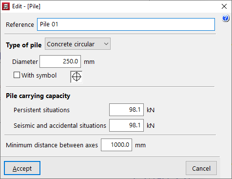
To create a generic pile, select “Generic pile” in the “Pile selection” window and, in “Selected pile”, click “Create”.
In the window that appears, you define the “Reference”, the “Type of pile” (either “Concrete circular” or “Concrete square”) along with its “Diameter” or “Width”, and the symbol used for it.
The “Pile carrying capacity” is the maximum design axial load that the pile can withstand at its head, and this value must be provided by the user. The program will issue a warning if this value is exceeded, following the distribution of forces analysed in the pile cap. This value must be defined for “Persistent situations” and for “Seismic and accidental situations”.
In addition, the “Minimum distance between axes” is defined, which specifies the minimum distance that must exist between the centres of adjacent piles.
After clicking "Accept", back in the "Pile selection" window, the "Penetration" field indicates the length of the pile that penetrates the timber pile.
| Note: |
|---|
| The pile should penetrate the timber pile to a depth of between 10 and 15 centimetres. |
The “Distance between pile axes” is also shown, if rectangular or linear pile groups have been selected, the “Number of piles”.
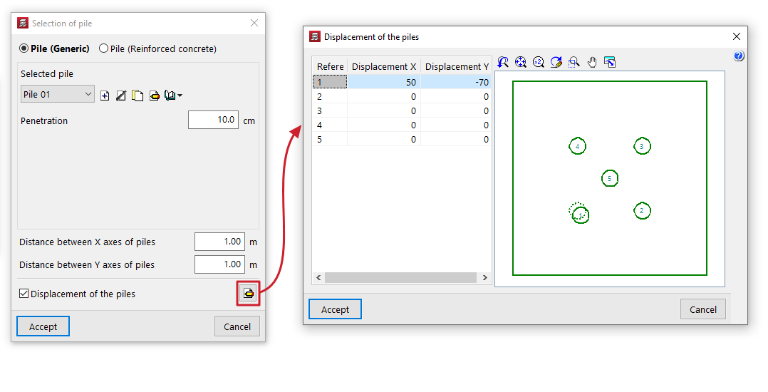
The “Displacement of the piles” option appears in some types of pile foundations and allows you to apply an “Displacement X” and a “Displacement Y” to each pile, to make minor adjustments to their position.
Selection and editing of reinforced concrete piles
The selection and editing of reinforced concrete piles is carried out by entering a new foundation element of the "Pile" type or by editing an existing pile with reinforced concrete piles, using the "Piles" option in the editing window.
General definition
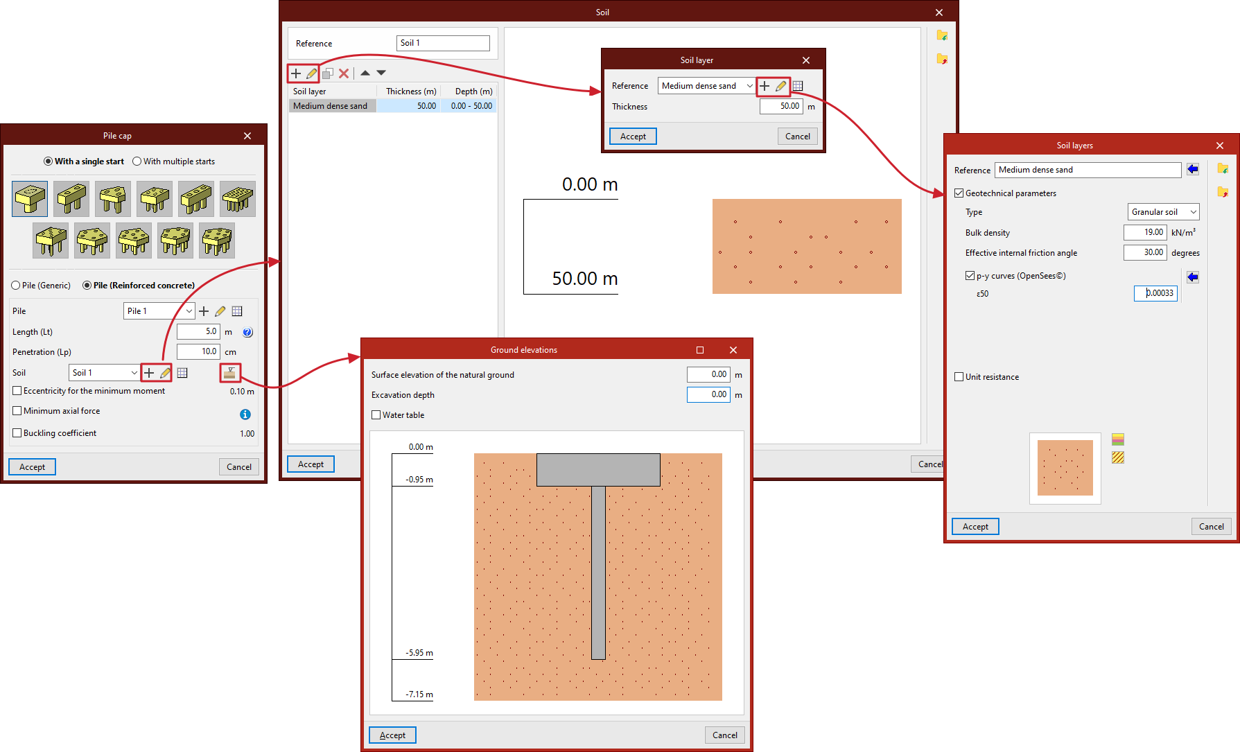
By selecting "Reinforced concrete pile" in the pile cap entry or editing window, it is possible to specify the characteristics of each pile, in addition to the ground data and other calculation parameters.
This option can analyse, verify and design piles as reinforced concrete elements, in addition to the analysis of the pile cap.
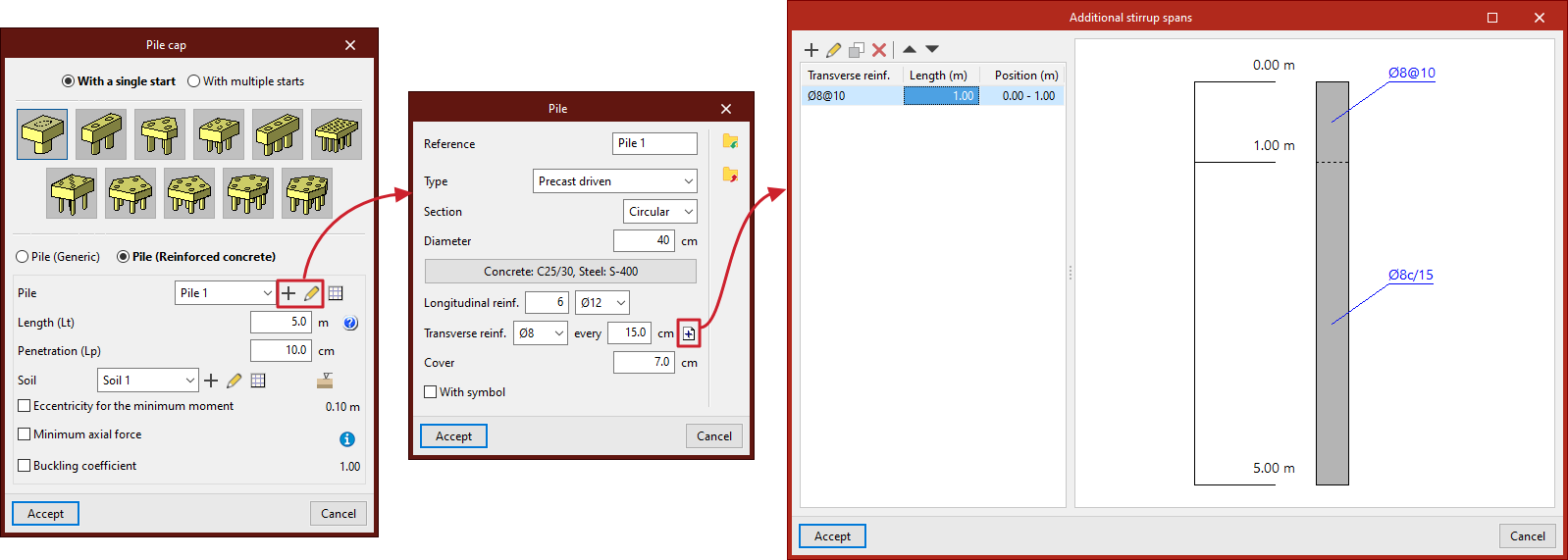
- From the "Pile" drop-down menu, pile types are created and selected with data on their geometry, material, section and reinforcement.
- The "Length (Lt)" refers to the length of the pile under the pile cap.
- "Penetration (Lp)" indicates the length of the pile that penetrates the pile cap. It is recommended to enter a value between 10 and 15 centimetres.
- Next, you must configure the "Terrain", which you can create, edit and save in a list of terrains using the tools on the right.
- The "Terrain elevations" option allows you to define the "Elevation of the natural terrain surface", the "Excavation depth" based on the previous one, and the elevation of the "Water table".
- Finally, by ticking the corresponding boxes, you can indicate the "Eccentricity for minimum moment", the "Minimum axial force" (based on a coefficient that multiplies its "Axial force") and the "Buckling coefficient".
- Where applicable, the "Spacing between pile axes" is also indicated and, if rectangular or linear pile caps have been selected, the "Number of piles".
- The "Pile displacement" option appears in some types of pile caps and allows you to apply an "X displacement" and a "Y displacement" to each of the piles in order to make small adjustments to their position.
Pile selection
In the "Pile" drop-down menu, when you click on "New" or "Edit selected type", you define:
- the "Reference" of the pile;
- the "Type" of pile ("Prefabricated driven" or "Cast in situ");
- its "Section" ("Circular" or "Square");
- its "Diameter" or "Width", depending on whether the pile section is circular or square;
- the "Materials" of the pile, including the "Concrete" and "Steel" of its reinforcement;
- its "Longitudinal reinforcement", which can be defined in "Corners" and for "Face X / Face Y") in square section piles;
- its "Transverse reinforcement" throughout the pile by default, with the option to define "Additional abutment sections" by clicking on the button on the right:
- each additional abutment section indicates the "Length" and "Transverse reinforcement" arranged in that section, which will replace the default transverse reinforcement; the additional transverse reinforcement sections defined will be arranged with respect to the pile head and will be represented in the plans of the foundation element, both in the pile section and in the attached information table;
- the concrete "Cover" over the reinforcement;
- and the symbol used for the pile (by activating the "With symbol" checkbox).
The information entered for each pile type can be viewed in a list of types and copied, edited or exported to files on disk using the corresponding options to be used in other models.
Definition of the ground
Each ground is defined by its "Reference" and several layers or strata that compose it:
In each "Stratum" you must define its "Reference", its "Thickness" and its characteristics, including the following:
- Geotechnical parameters (optional)
- Type (Cohesive soil / Granular soil / Rock)
- Apparent density
- Simple compressive strength
- Effective internal friction angle
- Internal friction angle
- p-y curves (OpenSees©)
- ε50
- J
- Unit resistances (optional)
- Tip
- Shaft
In the diagram below, the "Colour selection" and "Pattern selection" are made for the representation of the stratum in the terrain section provided by the program.
The information entered for each stratum can be consulted in a list of types and copied, edited or exported to files on disk using the corresponding options to be used in other models.
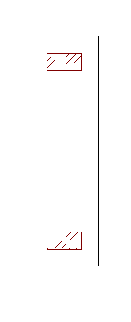
Layout of foundation elements on the floor plan
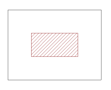
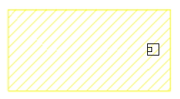
Once you have accepted the foundation element definition, if you move the mouse pointer over a support, it will turn yellow. The pointer takes the form of two concentric squares. If you click at this point, the foundation element will be positioned centrally beneath the support.
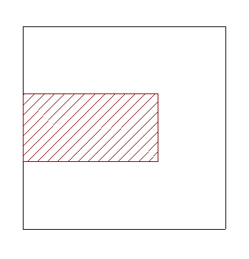
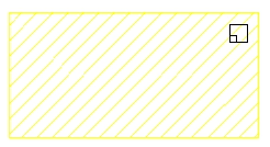
If you have chosen an eccentric footing, and the mouse pointer is positioned outside the bracket whilst the bracket is still selected, you can insert a corner or partition footing. The shape of the pointer indicates what the footing will look like.
You can click on the support again to reposition the foundation element.
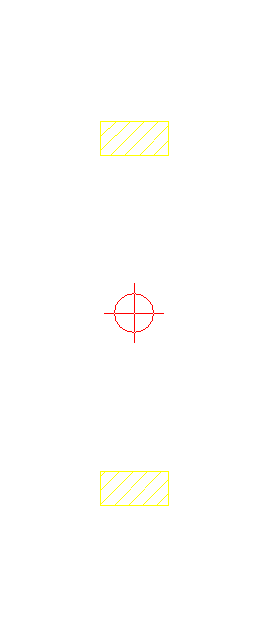
Layout of multi-column foundation elements on plan
If you have selected the “Multi column elements” option, after confirming the element definition window, you must click on several supports in succession – whether they are columns, screens or walls – or make your selection using a window.
Once the selection is complete, click the right mouse button. At this point, the insertion point for the foundation element appears; this is represented by a small circle with a cross and is located at the geometric centre of the selected set of supports.
As with the insertion of single-column elements, the shape of the pointer will indicate the type of footing: centre, corner or party wall. Clicking on this point will place the foundation element beneath the column group. The angle of the footing will be taken from the angle of the first column inserted.
Inserting strap and tie beams
Strap and tie beams can be entered via the “Beam input” and “Results” tabs. This option will be available when you are in a group where a column or screen defined as “With external connection” begins, or a wall with a continuous footing or “Fixity” at its base. To move to the desired group, use the “Move up group”, “Go to group” and “Move down group” options.
To insert a strap or tie beam, open the “Foundations” menu at the top and select the “Strap and tie beams” option.
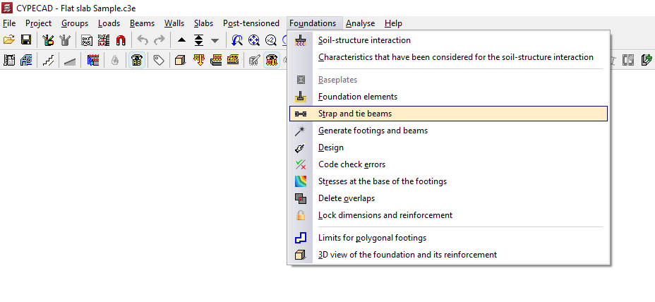
This opens the "Strap and tie beams" window, which displays the following options:
- Define beam
- Edit beam design
- Delete beam
- Balance ends
- Match
- Strap beam tables
- Tie beams tables
- Code check errors
Beam selection
The "Enter beam" option allows you to enter strap or tie beams.
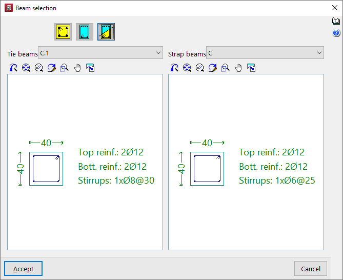
To do this, in the "Beam selection" window that appears, you must first select one of the following options: "Tie beam", "Strap beam" or "Beam with automatic centring at the ends":
Tie beams
If you select the "Tie beam" option, you can choose the type of tie beam from the drop-down menu at the top.
The central display shows the dimensions and the longitudinal and transverse reinforcement associated with the selected beam type.
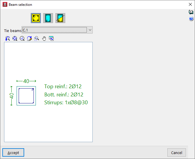
After clicking "Accept", the beam is inserted into the floor plan by left-clicking to select its start and end points, using, if necessary, the snap points on the beam heads and foundation elements such as footings and/or pile caps that have been drawn previously.
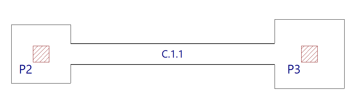
Strap beams
If the "Strap beam" option is selected, you must specify whether the beam "Balances at origin" or "Balances at end" by checking the relevant boxes. At least one of the two checkboxes must be checked. If you do not wish to balance either end, a tie beam will be used.
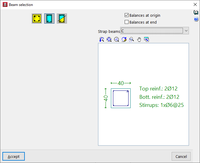
Next, as in the previous case, select the type of strap beam from the drop-down menu and, after clicking "Accept", draw the beam on the plan view using the left mouse button.
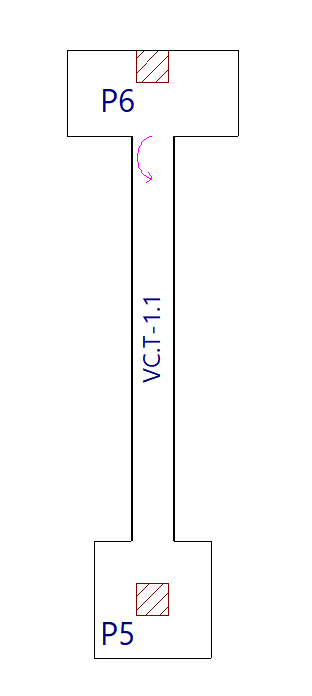
The start and end points of a centring beam depend entirely on the order in which the data is entered. Once entered, circular arrows appear at its junctions with footings or abutments. These arrows indicate that, at the end where they appear, the beam is centring the load from the footing or abutment along the longitudinal axis of the centring beam.
Beam with automatic centring at the ends
The "Beam with automatic centring at the ends" option allows the program to automatically identify the need for load centring at the ends when drawing beams in contact with corner or party wall footings.
To do this, after clicking on the option, you must specify the two possible beam types in the "Reference" drop-down menus, whether the beam is a tie beam or a strap beam.
After clicking "Accept", use the left mouse button to place the beam on the floor plan in the same way as in the previous cases.
This time, the program will automatically use a tie beam if it is placed between two centrally positioned footings, and strap beam if one of the beam’s ends is in contact with a corner or party wall footing, applying and displaying load centring at the end where necessary.
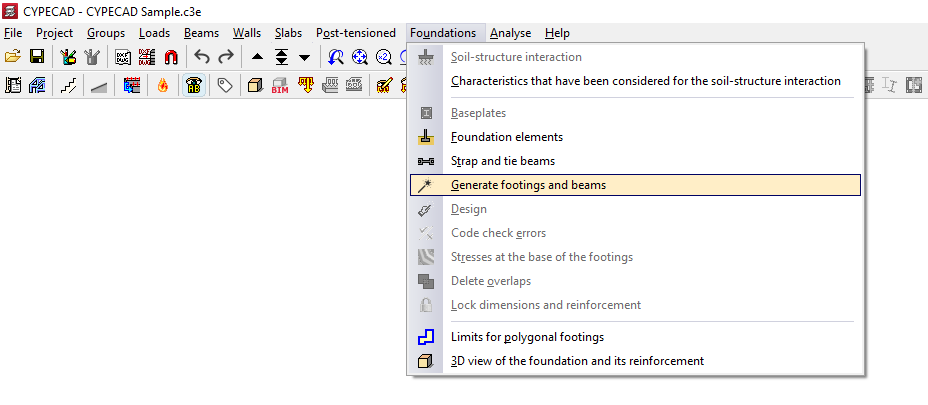
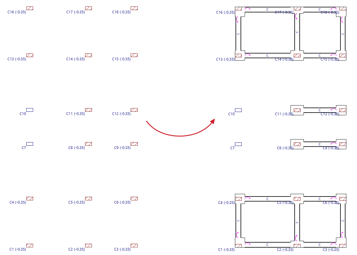
Generating footings and beams
The "Generate footings and beams" option, available in the "Foundations" menu on the “Beam input” or “Results” tabs, allows you to automatically create footings and centring beams based on the layout of the beam starts on the floor plan and in accordance with the specified parameters.
Options in the "Footing generation" window
The first parameters allow you to configure the generation of beams between footings. The program will generate beams if the axis of one column facing another is within a distance from the axis of the generating column that is less than the "Viewing distance (D)", provided that the angle formed by them falls within the "Viewing angle (A)".
You can also define the "Maximum separation between column axes to create footing". The program will generate a composite footing for columns that are spaced less than this value apart.
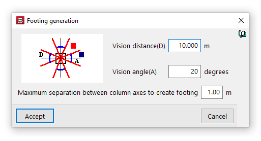
After clicking "Accept", the program will read the column bases on the visible floor plan and generate footings at these points, as well as beams between the footings in accordance with the settings specified.
From here, users can modify the footings and beams generated using the other options in the "Foundations" menu to adapt them to the actual project conditions.
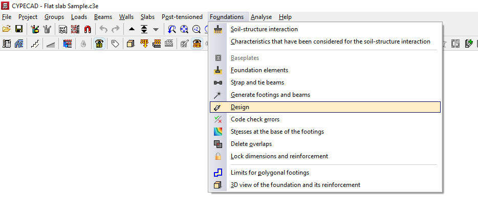
Designing foundation elements
The "Design" option, available in the "Foundation" menu on the “Beam input” or “Results” tabs, allows you to simultaneously design the elements that make up the foundation, including both their geometry and reinforcement.
This option will be available when you are in a group containing foundation elements such as footings, pile caps, centring beams or tie beams. To move to the desired group, use the options “Move up group”, “Go to group” and “Move down group”.
In order to carry out the foundation design, the structure must be designed in such a way that stresses are present at its base. If this is not the case, no stresses will be transferred to the foundation, meaning that the results obtained correspond to the minimum dimensions of the elements. The programme will display a dialogue box informing the user of this situation, so that the user can indicate whether or not they wish to continue.
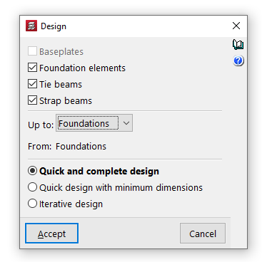
Options in the "Design" window
In the pop-up window that appears when you click on this option, you can tick the boxes for "Baseplates", "Foundation elements", "Strap beams" and "Tie beams" to specify the elements you wish to design.
Further on, in the drop-down menus "Up to" and "From", you select the floor groups for which you wish to analyse the foundation dimensions.
Next, the type of design to be carried out is specified.
- In the case of a "Quick and complete design", all foundation elements are sized in a single step, without taking into account the geometry entered by the user.
- If "Quick design with minimum dimensions" is selected, this is also performed once only; in this case, the dimensions entered by the user are checked and modified only if necessary.
- Finally, selecting "Iterative design" carries out the design of all foundation elements over three iterations, as any change in the stiffness of a strap beam affects the analysis of the footings to which it is connected.
Clicking "Accept" starts the design process. Once this is complete, you can use the "Check errors" option in the "Foundations" menu and select each element to view a detailed list of checks.
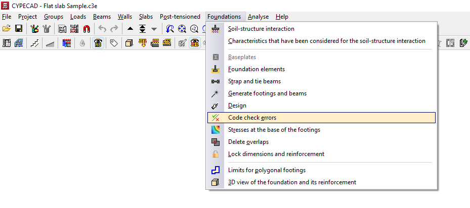
Errors in the verification of foundation elements
The "Code check errors" option, available in the "Foundations" menu on the “Beam input” or “Results” tabs, allows you to check the results obtained for the foundation elements following the analysis.
On the screen, foundation elements that do not present any problems are shown in black, whilst those that do are shown in red.
Check report
If you use this option and left-click on each item, you will be taken to the detailed list of checks.
Toggle the checkbox at the top to indicate whether you want to "Only show the failed checks" or all of them.
In the central section, a list is displayed showing the "Status" of each "Check". Clicking on each line brings up a detailed list of that check in the viewer at the bottom.
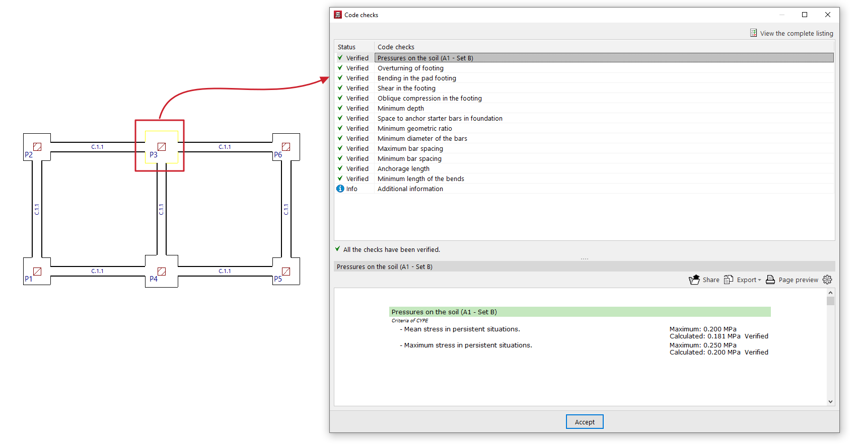
In the top right-hand corner, you can "View the complete listing" for each element, which you can "Share", "Export" in various formats or "Print".
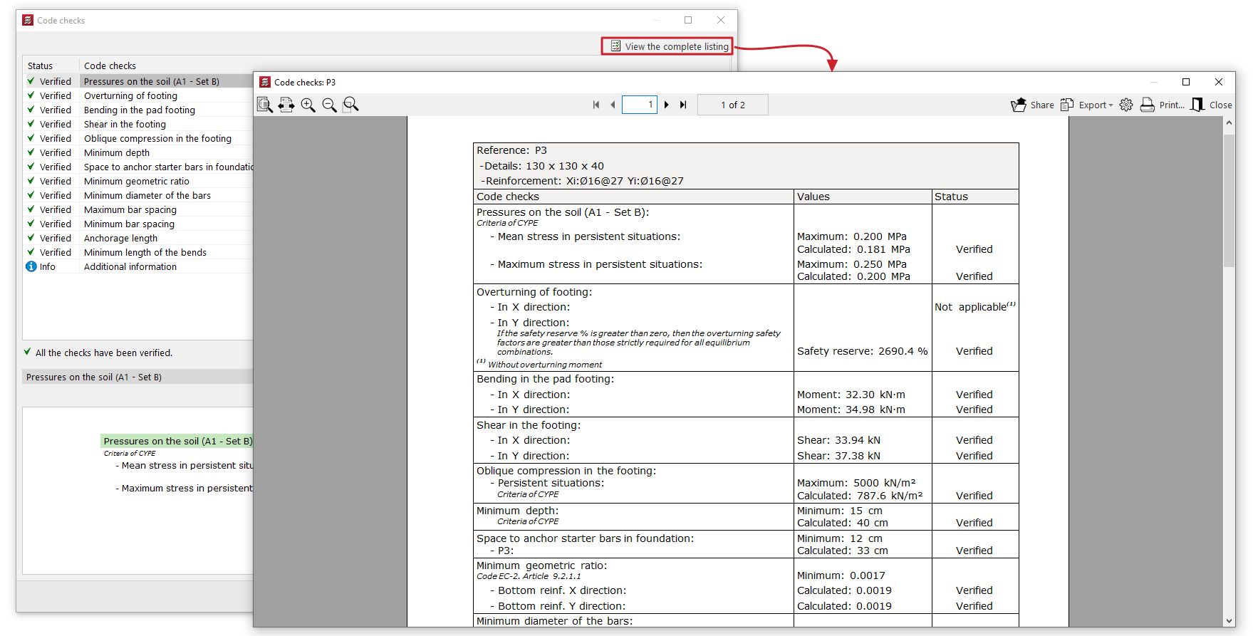
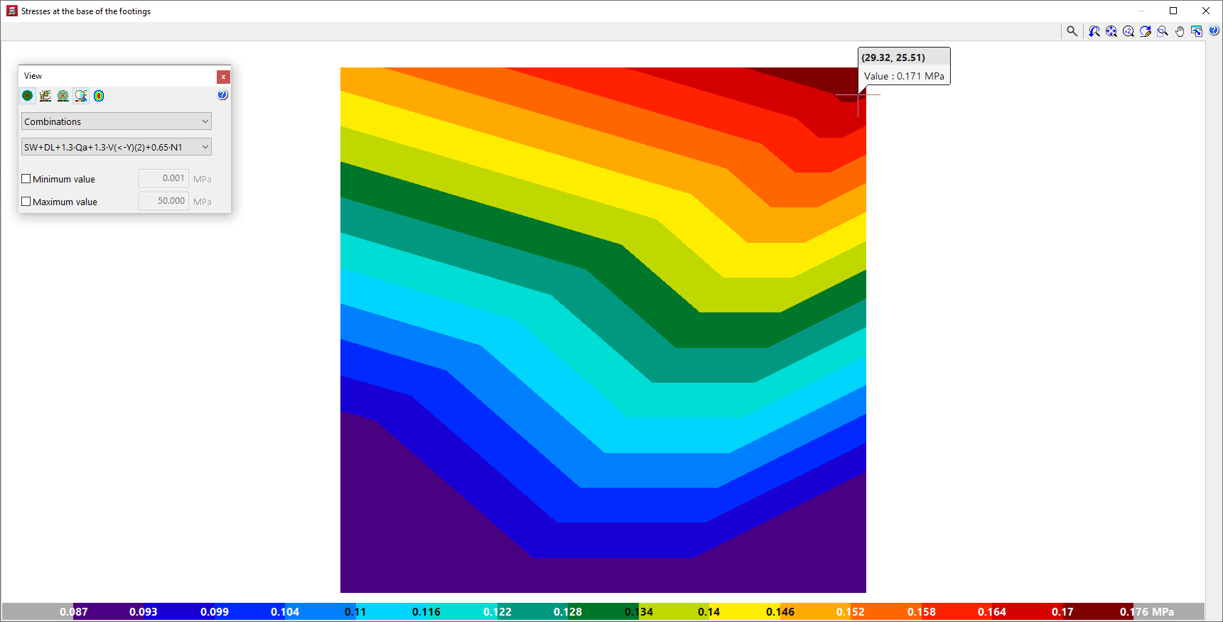
Diagrams of soil pressure in footings
The soil pressure diagrams at the base of the footings can be consulted in CYPECAD and CYPE 3D. This makes it possible to evaluate the suitability of the solution adopted for the foundation, as well as the distribution of loads on the ground and the behaviour of each footing.
- In CYPECAD, the "Stresses at the base of the footings" option can be used to view the stress diagrams at the base of all footings and is located in the "Foundation" menu, visible in the "Beam definition" and "Results" tabs. The stress diagram at the base of each footing can also be accessed through its editing menu (from "Foundations", "Foundation elements", "Edit"), by clicking on the "Stresses" option.
- In CYPE 3D, from the "Foundation" tab, it is also possible to access the stress diagram at the base of each footing through its editing menu (from "Foundation elements", "Edit"), by clicking on the "Stresses" option.
In either case, the program opens a consultation window showing the stress diagrams at the base of the footings with a colour gradient. The colour scale at the bottom acts as a legend and indicates the values represented in the diagram.
This representation is similar to the one used in CYPECAD in the "Contour plots" tab for checking the results of slabs and waffle slabs.
In addition, by hovering the cursor over each point in the diagram, the program displays an information text with the coordinates of the point, the value of the voltage shown at that point and, as the case may be, the combination in which it occurs.
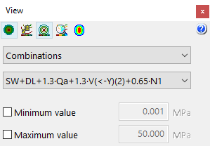
Stress diagram display settings
The floating window is used to adjust the display of the stress diagrams by means of the following options:
- The following options are available at the top:
- The "See contour plots", "See contour lines with values" and "See isolines without values" options can activate the display of the information in the indicated formats.
- Alternatively, users can "Automatically scale when zooming in" so that colours, lines and values displayed on the screen are adjusted according to the visible area when zooming in.
- Optionally, the "Colours for the representation of contour plots" can be modified, including the range and number of colours.
- Worst case / Combinations / Maximum
In this drop-down menu, users select whether the following voltage values are to be displayed or not:- Worst case
Displays the worst-case stress of any combination at each point. At each point, the stress shown may belong to a different combination. - Combinations
Displays the stresses of a particular combination chosen by the user, to be selected in a second drop-down. - Maximum
Displays the results of the combination resulting in the maximum stresses.
- Worst case
- Minimum value / Maximum (optional)
- By activating these boxes and entering a numerical value in the corresponding fields, the minimum and maximum values of the colour gamut range of the representation can be set.
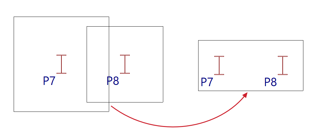
Deleting overlaps between footings
Foundation elements may overlap with others at the same elevation after manually modifying their geometry or performing the overall design of the foundation.
In this case, you can adjust the geometry again to avoid this situation, or use the "Delete overlaps" option, available in the "Foundations" menu on the “Beam Input” or “Results” tabs, to automatically delete the overlaps.
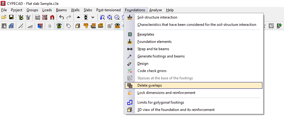
In this way, the program will place common footings for several foundations at the points where they overlap.
Locking the dimensions and reinforcement of foundation elements
The "Lock dimensions and reinforcement" option, available in the "Foundations" menu on the “Beam input” or “Results” tabs, allows you to lock both the geometry and the reinforcement of the selected foundation elements, preventing the program from modifying them during the design process.
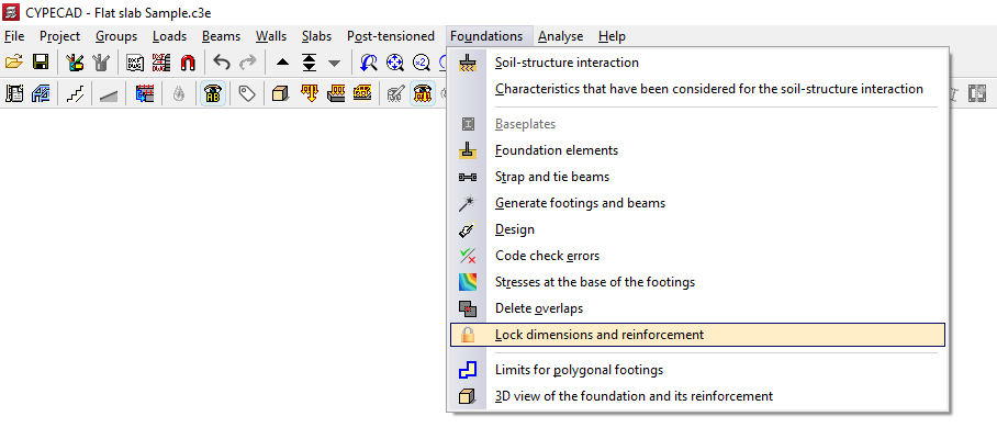
To do this, after clicking on the option, the program opens the "Lock dimensions and reinforcement" window, which allows you to select one of the following options:
- Locked dimensions and reinforcement
- Unlocked dimensions and reinforcement
The elements assigned to each of the two conditions are shown in a different colour. Each condition can be applied to footings, pile caps, strap beams and tie beams.
The "Assign" option allows you to select the foundation elements to which the selected condition should be applied, either individually or by dragging a selection area, whilst "Assign to all" applies the selected condition to all foundation elements on the floor. The "Finish" option closes the dialogue box.
Limits for polygonal footings
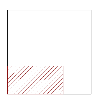
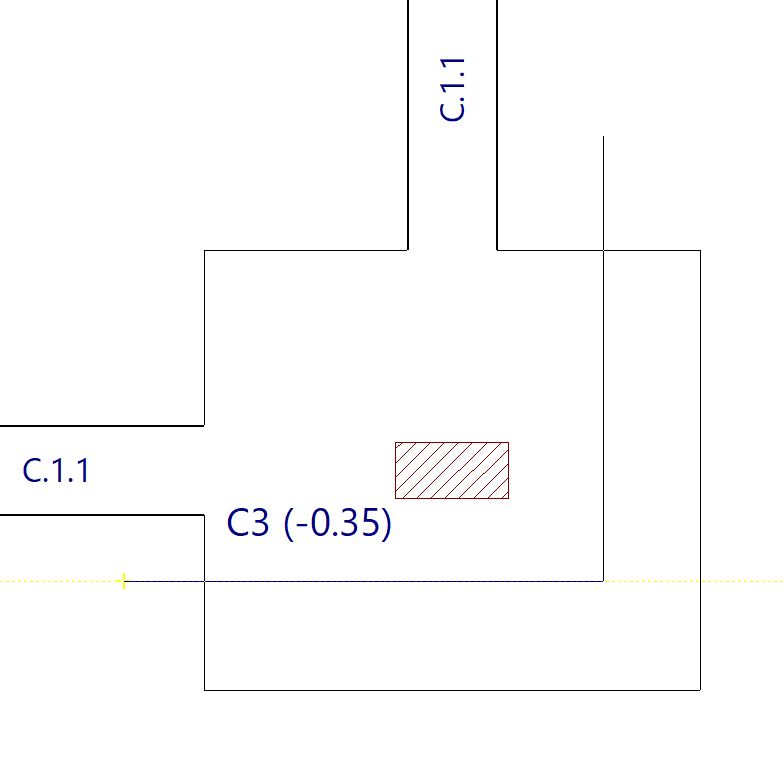
Foundation element limits are entered into the program using the "Limits for polygonal footings" option, available in the "Foundations" menu on the "Beam input" or "Results" tabs.
Foundation element limits allow you to define the presence of party walls, property limits or spaces reserved for other uses (such as lift shafts or service rooms) that must not be encroached upon by the geometry of the footings.
During the design process, the software prevents footings from exceeding the specified dimensions. The design of a footing may be subject to more than one limit.
Clicking on the option mentioned opens the "Foundation limits" window, which contains the following options:
- Entry by means of points
- Snap on DXF/DWG templates
- Delete
- Move
- New vertex
- Delete a section
Each of these features is described below:
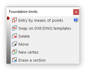
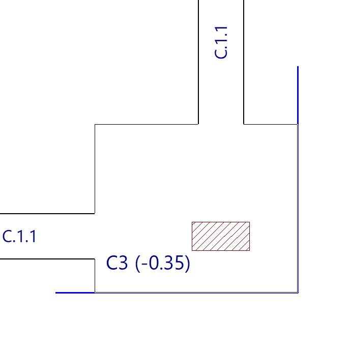
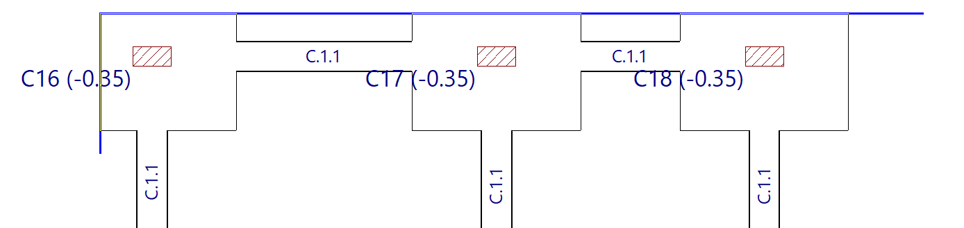
Entry by means of points
Using "Entry by means of points", you can draw a foundation limit by left-clicking on the points or vertices that define its plan geometry. To confirm your entry, right-click.
Limits are lines or polylines that define areas which cannot be occupied by constant-edge footings. When added, the limit clips the geometry of any footings already entered.
The section of the footing that includes the starter bar counters is the part that is retained and taken into account in the design.
These limits do not apply to tie beams, strap beams, pile caps or tapered footings.
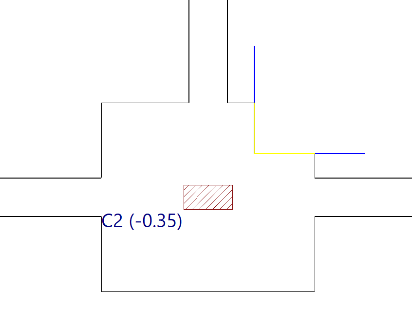
Snap on DXF/DWG templates
The "Snap on DXF/DWG templates" option allows you to automatically insert a foundation limit.
To do this, after importing a DXF or DWG template, left-click on a line or polyline defined within it. The program generates a foundation limit based on the geometry of the selected element.
Delete
The "Delete" option allows you to delete a previously entered foundation limit.
Select the limits to be deleted using the left mouse button or by dragging to highlight an area, then click the right mouse button to confirm their deletion.
Move
Use "Move" to move a section or a vertex of a foundation limit.
You can modify the geometry of the limit by left-clicking on a vertex to select it and then left-clicking again to set its new position.
To move a section of a foundation limit, left-click anywhere on the section and then left-click again at its new position.
New vertex
Clicking on "New vertex" adds a new vertex to any section of an existing foundation limit.
To do this, use the left mouse button to select the element where you want to insert the new vertex, and then select the desired point.
Delete a section
By using "Delete a section", you can delete a section of an existing foundation limit. As before, select the sections using the left mouse button and click the right mouse button to confirm their deletion.
If an intermediate section is deleted, the limit on which it acts is split into two new limits.
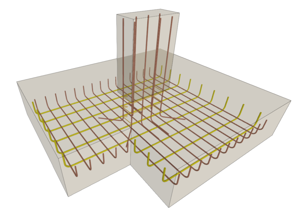
3D view of the foundation and its reinforcement
The "3D view of the foundation and its reinforcement" option, available in the "Foundations" menu under the “Beam input” or “Results” tabs, allows you to open a window where the program displays a three-dimensional representation of the geometry of the footings, pile caps, strap beams and tie beams, as well as the details of the reinforcement obtained from the analysis.
If reinforced concrete piles have been used instead of standard piles, their geometry and reinforcement are also shown.
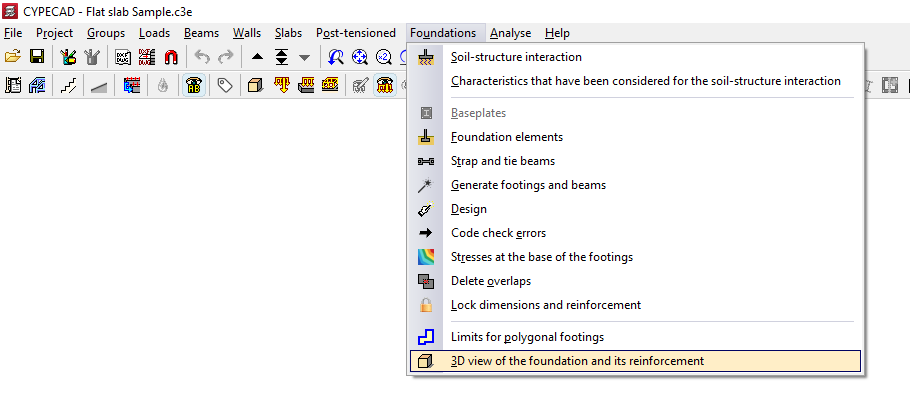
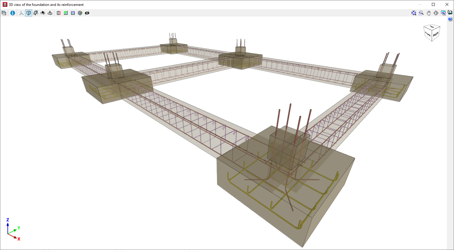
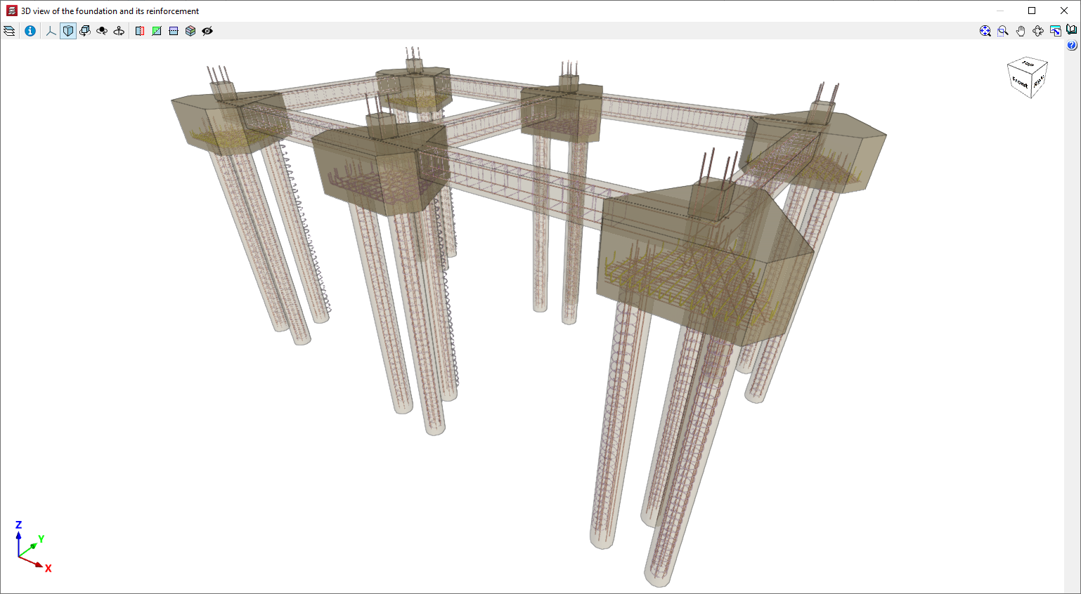
Table of contents
Complete your tour of CYPECAD by exploring the other available sections:
- Introduction
- Introduction and creating new jobs
- General data configuration
- Defining floors and groups of floors and inserting columns, shear walls and starts ("Column input" tab)
- Inserting beams, walls, floor slabs, foundation elements and special elements, and structural analysis (the "Beam Input" tab):
- Checking analysis results and editing elements (the "Results" tab):
- Options on the "Contour plots" tab
- Printing documents and exporting data
- More information:
- General features of CYPECAD