
Panel manager options
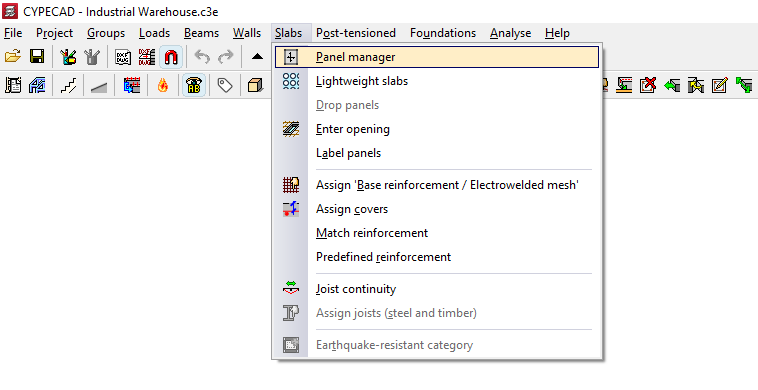
The "Panel manager" option, available within the "Slabs" menu on the "Beam input" tab, provides access to a menu containing various options relating to the input, viewing and modification of the structure’s floor slabs.
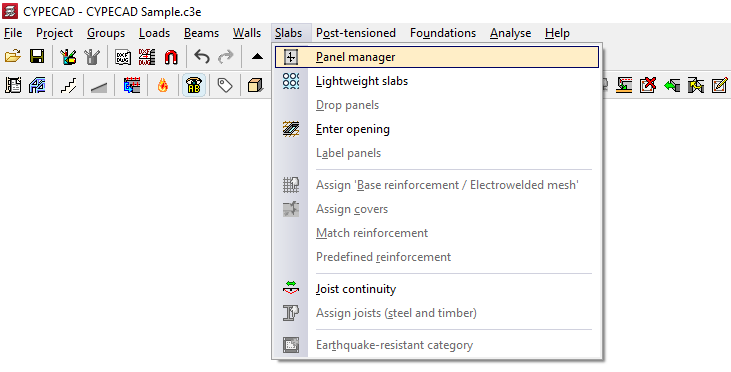
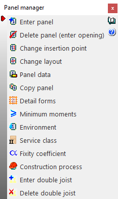
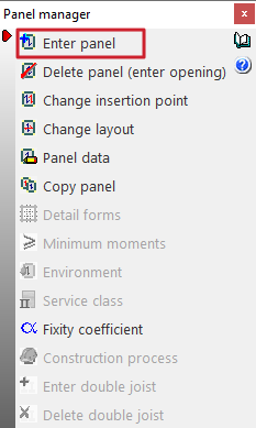
The available options are as follows:
- Enter panel
- Delete panel (enter opening)
- Change insertion point
- Change layout
- Panel data
- Copy panels
- Detail forms
- Minimum moments
- Environment
- Service class
- Fixity coefficient
- Construction process
- Enter double joist
- Delete double joist
Enter panel
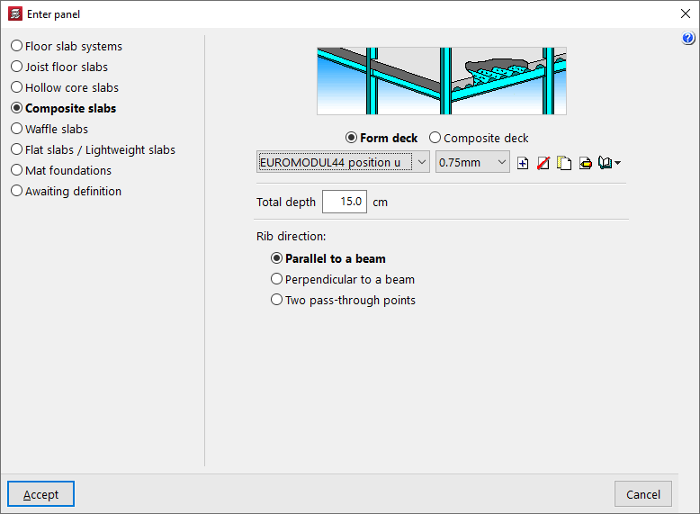
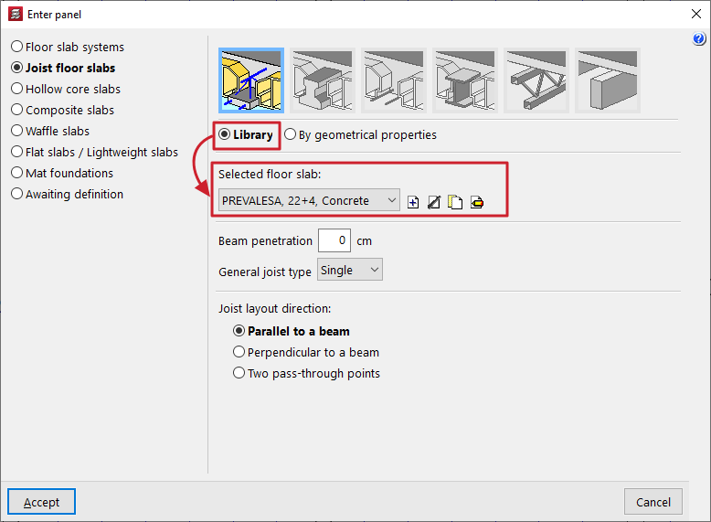
This allows you to select a floor slab type (in the "Enter panel" window that appears) and then insert a slab of the selected type into a closed perimeter on the floor plan, previously defined by beams and/or walls.
The following types of floor slabs are available:
- Floor slab systems
- Joist floor slabs
- Hollow core slabs
- Composite slabs
- Waffle floors
- Flat slabs / Lightweight slabs
- Mat foundations
- Awaiting definition
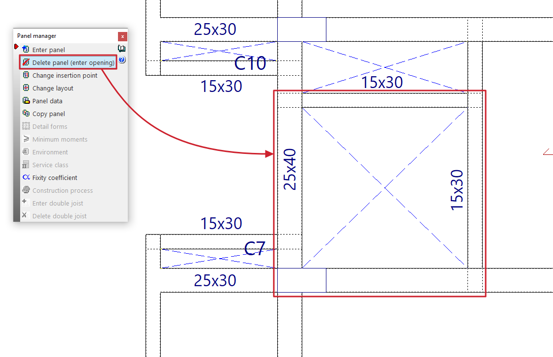
Delete panel (enter opening)
This allows you to remove a floor slab and insert an opening within a closed perimeter on the floor plan, previously defined by beams and/or walls.
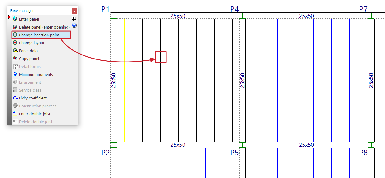
Change insertion point
This option allows you to change the insertion point of the joist, rib or reinforcement of the selected panel.
To do this, after selecting the option, you must select the panel. Then, click on the new point through which you want the joist, rib or reinforcement of the panel to be inserted.
This procedure can be useful for re-routing the ribs if there are small openings in the floor slab; in this way, the opening can be aligned with the hollow blocks or lightweight sections.
| Note: |
|---|
| Joists in adjacent sections may be misaligned by up to 20 centimetres whilst maintaining continuity with one another. |
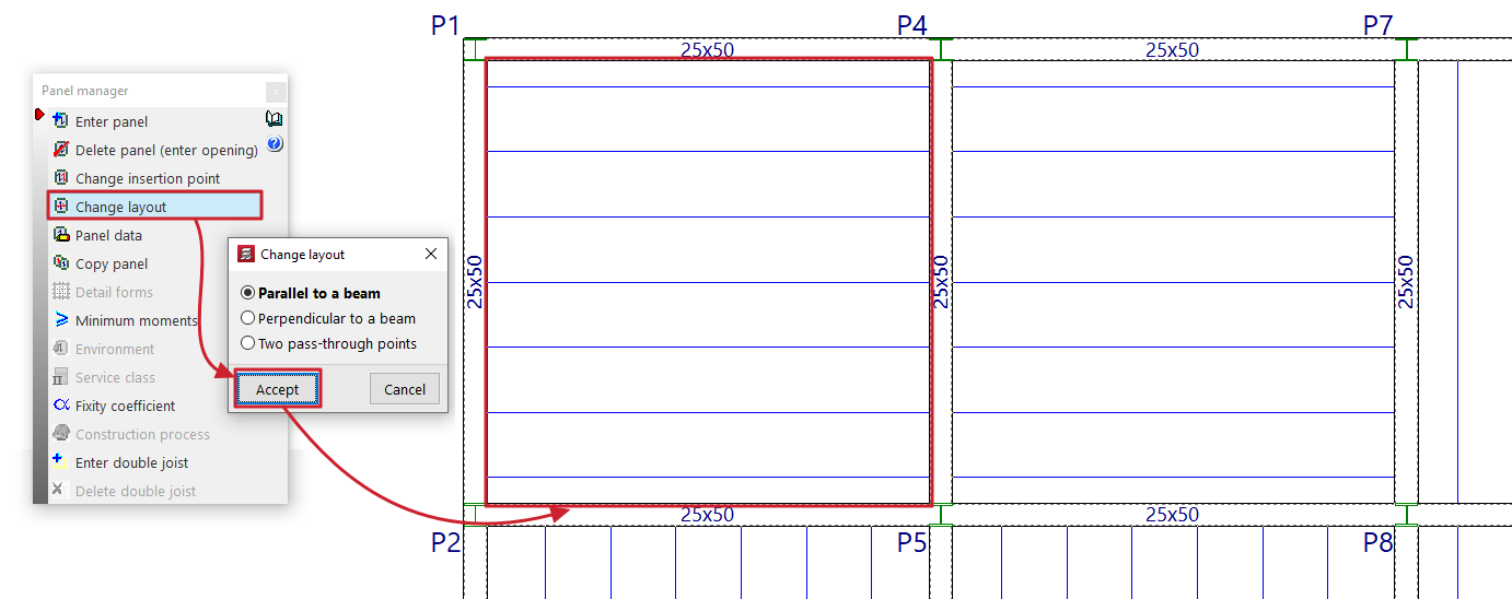
Change layout
This option allows you to change the direction of the joists, beams or reinforcement bars in a panel.
To do this, you must first specify whether the direction to be defined is "Parallel to a beam", "Perpendicular to a beam" or defined by "Two points of intersection".
Next, select the panel with the mouse and then specify the new direction of the joists, beams or reinforcement by selecting a beam or the two required connection points.
When changing the layout of a panel, the reference point marked when the slab was installed remains in place.
Panel data
When this option is selected, the mesh number for each panel is displayed on the plan view (the drop panels, ribs or openings in each panel generate meshes with their corresponding numbers).
Next, when you left-click on a panel added to the floor plan, a dialogue box displaying its properties will appear.
For example, the data that the program displays for a joist floor is as follows:
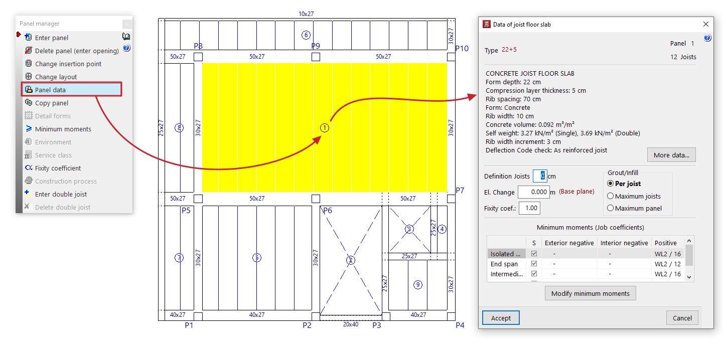
- First, the "Type" of the floor structure, the number of "Sections" and the number of "Joists" are displayed.
- The main technical specifications of the selected floor slab are then listed; the full description can be viewed by clicking the "More data" options.
- You can change the length of the joist section that is inserted into the beam by entering the value in "Enter joists". This is used solely for the purposes of measuring and drawing the floor structure on the plan.
- In "Slope", you can apply a positive or negative horizontal slope value to the panel relative to the elevation of the current floor plan's base plane. This option is equivalent to the one available under "Groups > Sloped slabs / Elevation changes". Furthermore, the elevation changes entered for each slab will appear in the list of slabs with elevation changes managed via this latter option.
- It is also possible to modify the fixed support coefficient ("Fixed support coefficient") for the ribs around the entire perimeter of the panel. A value of 0 corresponds to hinged elements, whilst a value of 1 indicates a fixed support. Intermediate values are permitted to simulate partial fixed supports.
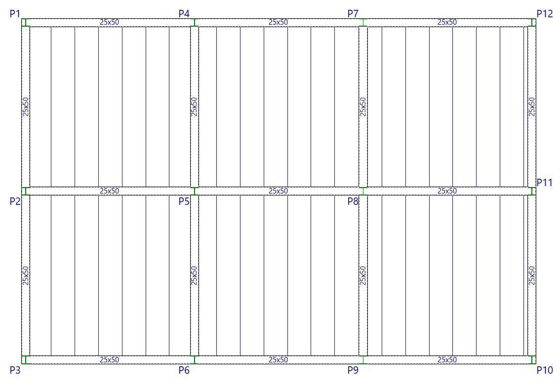
- Where compression reinforcement is required in the area where the top reinforcement is located, the forms shall be removed until they are no longer necessary. This shall be indicated on the floor plan by a solid line representing the joists, shown in blue. The options in the "Infill" section allow you to configure the removal of forms or lightweight elements:
- if "Per joist" is selected, the required solid section is applied to each joist;
- if "Maximum joists" is selected, the joist requiring the most reinforcement is identified, and this is applied to all adjacent joists;
- if "Maximum panel" is selected, the joist requiring the maximum solid section is chosen and applied to the entire panel;
- Finally, the "Minimum moments" assigned to the panel via the corresponding option in the "Panel manager" menu are displayed. You can also modify these directly for the selected panel by clicking on the "Modify minimum moments" option.
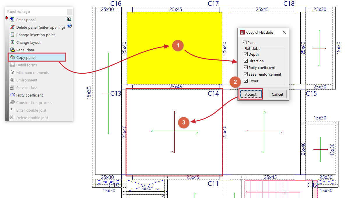
Copy panels
This option allows you to copy data from one panel to another.
First, left-click on the panel from which you wish to extract the information. The program will then display a dialogue box where you can select the data to be copied by ticking or unticking the relevant boxes.
Once you have accepted, use the left mouse button to select the panels to which the data will be copied, either by selecting them one by one or by dragging to select an area.
If you wish to change the source panel, simply right-click and repeat the previous steps.
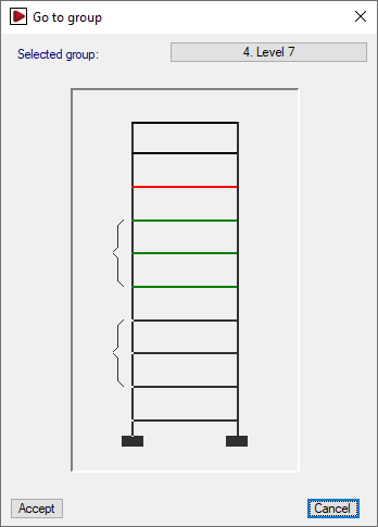
Copy panel from one group to another
It is also possible to copy data from a panel in one group to another panel belonging to a different group of floors.
To do this, after clicking the "Copy panels" option, right-click and select the group containing the source panel from the “Go to group” window.
Once you have selected the sheet and confirmed the dialogue box specifying the data to be copied, the program will return to the group of floors that was visible when the option was selected.
| Note: |
|---|
| Copying panels also ensures that the joists and ribs of the panels are aligned and that there is continuity in the assembly. It is therefore advisable to insert one panel and copy the rest, as inserting them all manually may result in a slight difference in the alignment of the ribs (greater than 20 cm), which could prevent continuity in the floor slab. Furthermore, in the case of a cantilevered joist floor, the load-bearing element is the joist, so the joists from the panel adjacent to the cantilever must be copied. |
Detail forms
This option will be available once at least one waffle slab panel has been defined on the floor.
When you click on this option, the actual layout of the ribs in the waffle slabs and the details of the forms will be displayed.
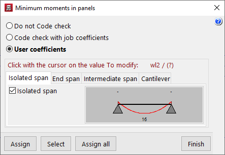
Minimum moments
This option allows you to modify and assign the minimum positive and/or negative moments to be withstood by joist floors, lightweight slabs and composite slabs; it will be available if there is at least one section of these types on the floor.
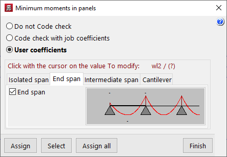
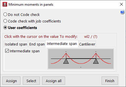
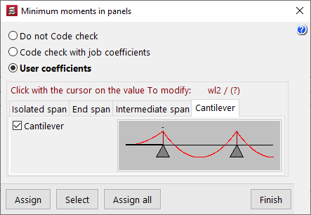
In the window that appears when you click on "Minimum moments", the program allows you to select one of the following options:
- Do not Code check
The program will not perform the minimum moment check on the marked floor slabs. - Code check with job coefficients
The program will use the minimum moments defined under "Structure > Slab options > Minimum moments to cover with slab reinforcement". - User coefficients
Allows you to modify the coefficients that define the minimum moments according to the type of span. To modify these coefficients, left-click on the value to be modified in each of the diagrams that appear when selecting the different tabs (“Isolated span”, “End span”, “Intermediate span” and “Cantilever”). The coefficient is equivalent to the denominator 'A' in the expression p*L²/A, where 'L' is the span length and 'p' is the load.
| Note: |
|---|
| By default, the program assigns minimum positive moments of pL²/16 to isolated and intermediate spans and pL²/12 to end spans. |
Environment
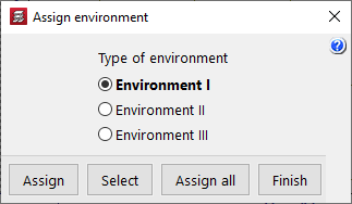
This option will be available once at least one panel of hollow core slabs has been defined on the floor plan.
When you click on the option, you can select the type of environment to apply ("Environment I", "Environment II" or "Environment III").
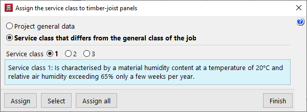
Service class
This allows you to select and assign a specific service class to timber joist floors.
This may be the one defined under "General project data" (within the "Project" menu) or a "Service class that differs from the general class of the job", in which case the specific class must be selected.
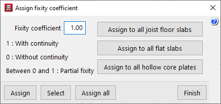
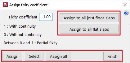
Fixity coefficient
This allows you to define an "Fixity coefficient" between 0 and 1 and assign it to a floor slab consisting of joists, flat slabs or hollow core slabs. This coefficient defines the degree of fixity of the joists, panels or slab edges into the faces of all the perimeter beams that form the perimeter of the slab.
A value of 0 indicates that the joists, slabs or slab edges are hinged (they are not connected to the beam), whilst a value of 1 indicates that they are rigidly connected to the beam (there is a continuous connection with the beams). Intermediate values are permitted to define partial fixed connections.
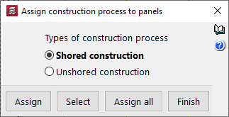
Construction process
This option will be available once at least one panel system has been defined on the floor plan, and allows you to assign the "Construction process" to it for analysis purposes. This can be:
- Shored construction
In this case, a fixity coefficient of 1 is assumed at the edges of the slab, which allows the simulation of a construction of these slabs using support beams. With this option, the negative moments are usually greater than the positive moments. - Unsupported construction
In this case, a fixity coefficient equal to 1 – (Self-weight of the floor slab / Total load [including the self-weight of the floor slab, live load and dead loads]) is assumed. This allows for the two-stage analysis required when constructing this type of floor slab without beams. With this option, the positive moments are usually greater than the negative moments.
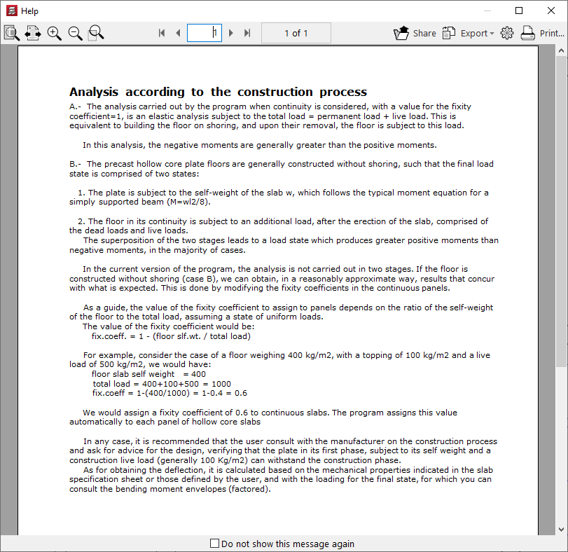
The button on the right provides access to detailed information about the analysis performed based on the selected construction process.
Options for assigning data to floor slabs
When using several of the above options ("Minimum moments", "Environment", "Service class", "Fixity coefficient" and "Construction process"), the program offers the following options for assigning the data to the panels:
- Assign
Allows you to select the panel to which you wish to apply the selected condition. - Select
Allows you to extract information from a selected panel on the floor plan. - Assign all
Applies the selected condition to all panels in the current group. - Assign to all joist floor slabs / Assign to all flat slabs / Apply to all hollow core slabs / Apply to all composite slabs
These tools appear only in some of the options mentioned and allow you to apply the selected condition to all floor structures of the specified type present on the floor. - Finish
Closes the options window.
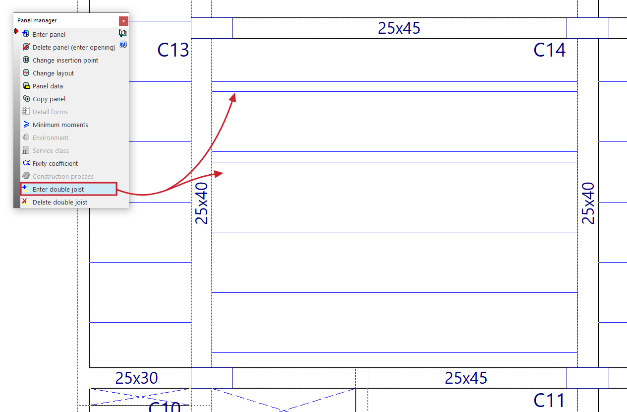
Enter double joist
This option allows you to define double and/or triple joists, and will be available once at least one joist floor slab or floor slab system has been defined on the floor.
To do this, tap to the right or left of one of the joists in a floor slab. Doing so will insert a double joist (if a single joist is selected) or a triple joist (if a double joist is selected) at the selected position.
Delete double joist
This option allows you to remove double and/or triple joists defined in joist floors or in floor slab systems entered on the floor plan.
To do this, left-click on the double or triple joist you wish to remove.
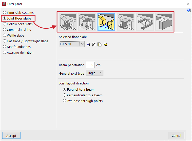
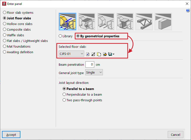
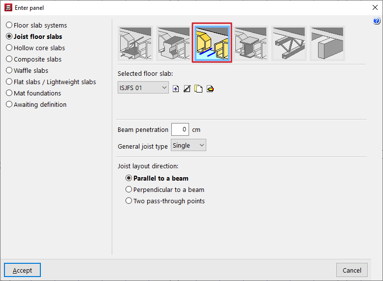
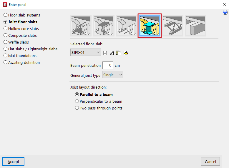
Inserting joist floor slabs
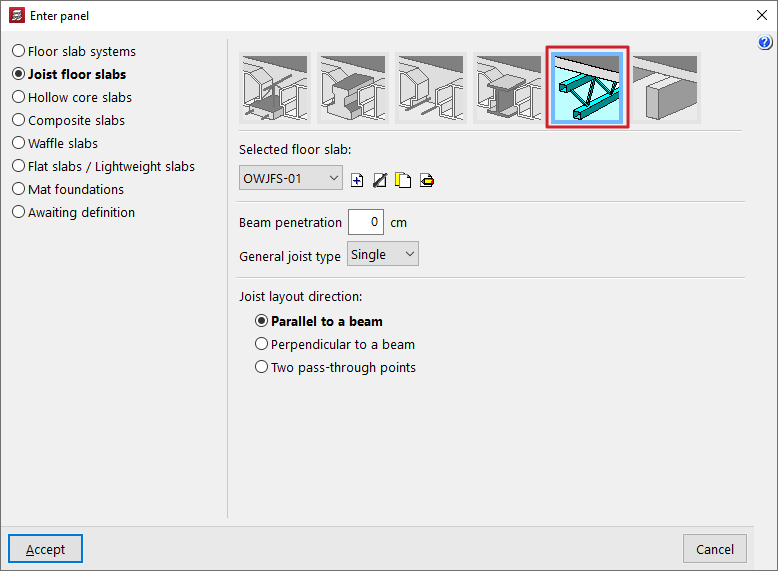
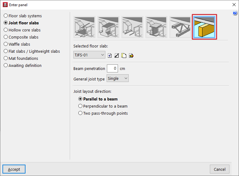
The "Joist floor slabs" option, within the "Enter panel" window (accessible via "Slabs > Panel manager”), allows you to enter precast concrete joist floors, both reinforced and prestressed, as well as in-situ, steel, joist and timber floor slabs.
Selecting the type of joist floor slab
The type of joist floor slab to be entered is selected using the options at the top of the "Enter panel" window:
- Reinforced joist floors / Prestressed joist floors
These options allow you to input prefabricated reinforced or prestressed joist floors in two ways: by using the "Library" types or by defining them "By geometric characteristics". - In-situ joist floors
This option allows you to include concrete joist floors that are fully assembled on site. - Steel joist floors
This option allows you to insert single-T or double-T rolled steel and isostatic steel joist floors. - Joist floor slabs
This option allows you to insert truss and isostatic steel joist floor slabs. - Wooden joist floors
This option allows you to input wooden joist floors with rectangular cross-sections and isostatic floors.
Next, in the "Selected floor slab" drop-down menu at the bottom, select and configure the properties of the specific floor slab to be entered.
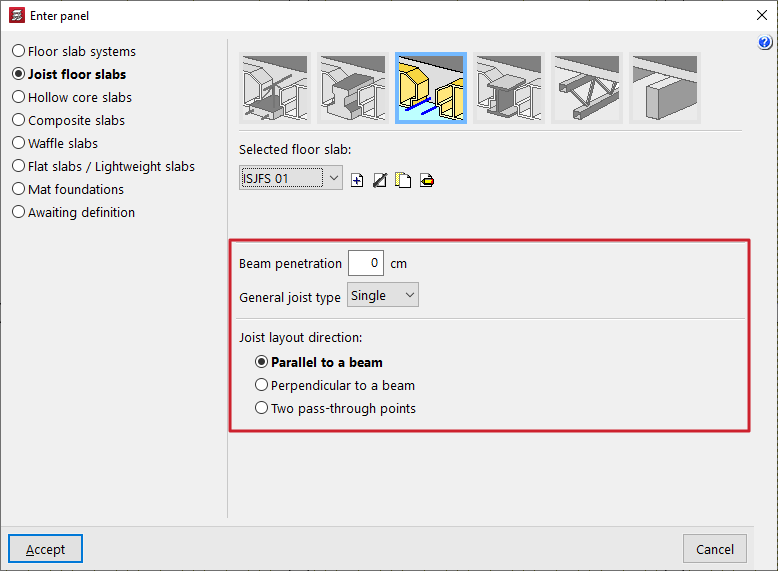
Additional options and on-plan insertion
In the "Beam penetration" field, enter the length of the joist section that is inserted into the supporting beam. This is used solely for the purposes of measuring and drawing the joists on screen and in the drawings.
The "General joist type" field specifies whether all the joists in the floor slab are single, double or triple.
| Note: |
|---|
| If you need to change the number of joists at a specific point in the panel after it has been entered, use the "Enter double joist" and "Delete double joist" options in the menu. |
At the bottom of the window, you can specify the "Joist layout direction". These can be:
- "Parallel to a beam" or "Perpendicular to a beam", to be selected by the user;
- Alternatively, you can mark "Two pass-through points" on the floor plan to indicate the direction of the joists.
Once you have accepted, moving the cursor over the various closed outlines on the plan view will highlight the areas where the panel can be inserted. Then, click the left mouse button to insert the panel into that area.
Finally, using the left mouse button, you must select the beam or the support points that define the direction of the joists. The panel will be defined using this data and will be displayed on screen.
Selecting reinforced or prestressed joist floor slabs from the library
When defining reinforced or prestressed joist floor slabs (in the "Enter panel" window) and for certain standards, the "Library" option is available.
If the "Library" option is selected, users must choose the "Selected floor slab" from those available for the project. The controls on the right allow you to "Add", "Delete", "Copy" or "Edit" these floor slabs.
When you use these controls, the program opens an editing window where you can configure each library joist floor.
To import data from manufacturers, use the tools to the right of the drop-down menu:
- The "Import predefined data" option opens an import window where you tick the "Selected" box to import data for each of the desired manufacturers.
- The "Import from library" and "Export to library" options allow you to import and export data to files with the extensions .fva (prestressed joist files) or .fvp (prestressed joist files), which are saved to the selected path on the hard drive.
- In addition, the "Initial import" option allows you to select the "Default" manufacturers that will be imported automatically when creating new projects in the program.
| Note: |
|---|
| For certain specifications, if the user wishes to enter their own data, they can do so using the "Floor slab data editor" program. This editor can be downloaded from the following link and allows you to generate a file with the .fva or .fvp extension that can be imported directly into CYPECAD. |
In the editing window for each type of floor, you should first enter a "Reference (Optional)" for the floor.
Next, the "Type of floor slab" is defined by selecting a manufacturer from the "Specification" drop-down menu and, from the second drop-down menu, the specific "Floor slab" from those offered by the selected manufacturer.
Once you have selected a specific library floor slab, the program will display its main characteristics at the bottom of the screen, such as the following:
- the rib spacing;
- the type of concrete used on site and in the joists;
- or the type of steel used in the various reinforcement systems (the lattice steel, the assembly steel, and the positive and negative reinforcement in the case of reinforced joists, or the prestressing steel and the negative reinforcement in the case of prestressed joists).
On the right, a designed section of the joist for the selected floor slab is shown.
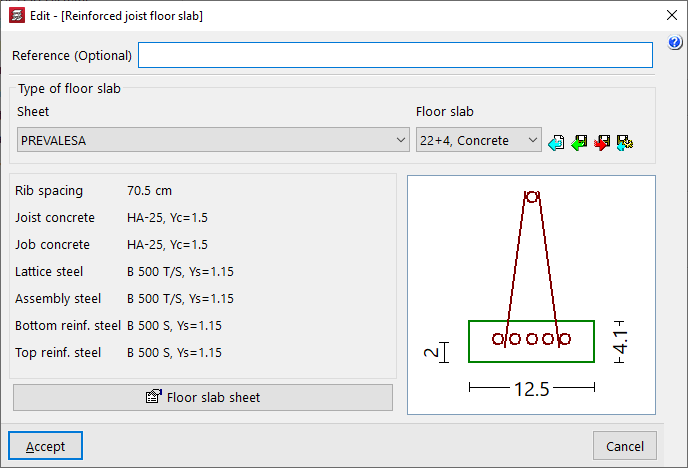
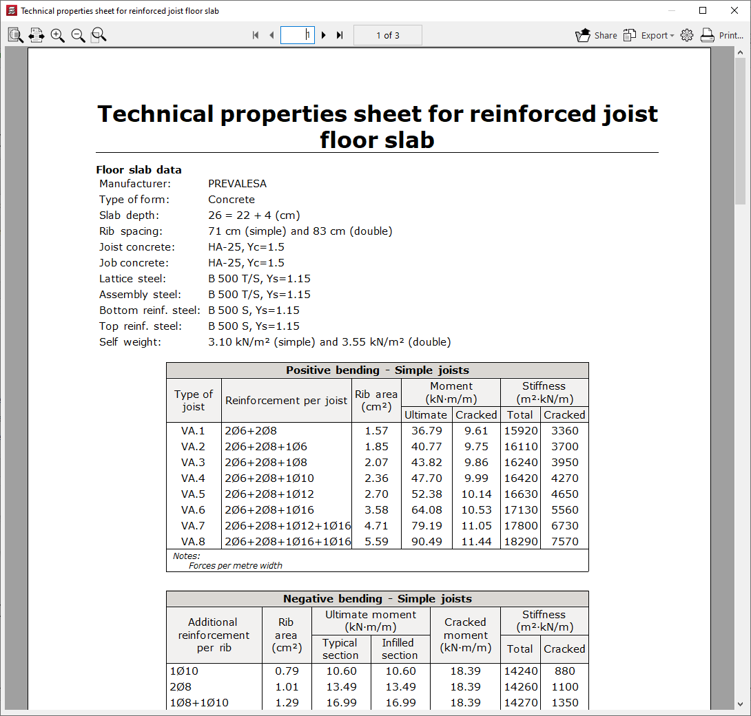
At the bottom, the "Floor slab specifications" option opens a separate window displaying the technical properties of the floor slab. The following information is shown here:
- the manufacturer, the type of hollow block, the slab depth and the materials used (concrete and steel);
- the centre-to-centre distance and dead load for single joists and double joists;
- and the data on the moments, stiffnesses and shear forces withstood by the floor slab, depending on the type of joist or top reinforcement per rib used.
Defining reinforced or prestressed joist floors based on geometric properties
When defining reinforced or prestressed joist floors (in the "Enter floor" window), if the "By geometrical properties" option is selected, users must choose the "Selected floor slab" from those available in the project.
| Nota: |
|---|
| If the selected code does not allow you to select reinforced or prestressed joist floors from the "Library", the only option available will be to define the floor based on its geometric characteristics. |
The controls on the right allow you to "Add", "Delete", "Copy" or "Edit" these floor plans. It is also possible to access a "Library Manager" options menu to save information about the defined sections to files on the hard drive.
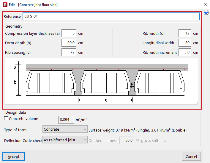
When you use these controls, the program opens a window where you can configure each joist floor slab according to its geometric properties.
Here, a "Reference" is first entered for the floor slab.
Next, the "Geometry" is defined by entering the following parameters:
- the "Compression layer thickness (a)";
- the "Form depth (b)";
- the "Rib spacing (c)" between joists;
- the "Rib width (d)";
- the "Longitudinal width" of the form, which only affects the quantities of forms carried out in the "Form quantities report" (menu "File > Reports > Form quantities");
- and the "Rib width increment" or thickness of the ribs of the small form to be taken into account for the purposes of calculating deflection.
The first parameters (a, b, c and d) refer to the distances shown in the floor plan diagram displayed in the centre of the window.
| Note: |
|---|
| The value for "Rib width increment" allows the thickness of the web stiffeners or lightweight component to be considered when calculating the stiffnesses and the cracking moment required for the deflection analysis. This practice is common among the leading manufacturers of precast joists. If these partitions are not considered, the deflection given by the program for floor slabs defined by geometric characteristics will always be greater than that obtained with an equivalent floor slab defined in the library using reinforced or prestressed precast joists. The values for the "Increase in web width" depend on the type of hollow block or lightweight element. The following values are proposed: -Concrete lightweight block: 3 cm. -Ceramic lightweight block: 0 cm. -Polystyrene lightweight block: 0 cm. -Recoverable formwork: 0 cm. |
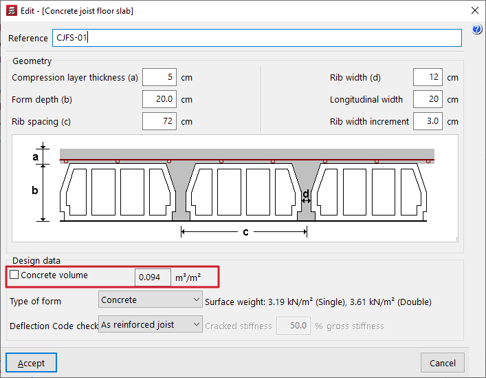
The "Calculation data" is defined below:
- The "Concrete volume" checkbox can be activated or deactivated:
- If this option remains deactivated, the program calculates the approximate volume of concrete per unit area, taking into account the geometric parameters entered in this window, and displays the updated value in the field on the right.
- If this option is activated, users can enter the concrete volume per unit area in the field on the right; this value may differ from that suggested by the program, thereby overriding it.
- In the drop-down menu "Vault type", select the vault material. This can be:
- Concrete / Ceramic / Polystyrene
In these cases, this information, together with the geometric parameters entered, allows the approximate "Surface weight" of the floor slab to be calculated for both single and double joists. These values are shown on the left. - Generic
Alternatively, you can select the "Generic" option to manually enter the surface weight of the floor slab with simple joists in the field provided on the right.
- Concrete / Ceramic / Polystyrene
| Note: |
|---|
| The "Concrete volume" displayed or entered by the user, as well as the "Unit weight" entered by the user, applies to a floor slab with single joists. In the case of double and triple joists, the program calculates the corresponding volumes based on the geometry entered. |
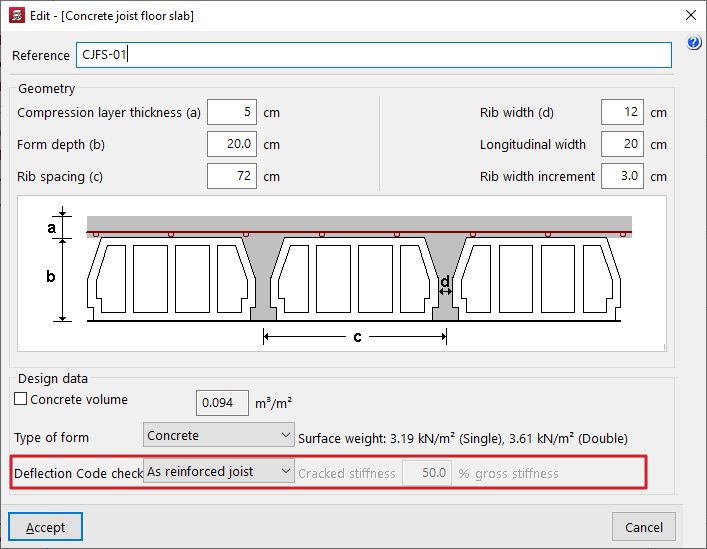
- The last drop-down menu indicates whether the "Deflection check" that the program carries out on these floor slabs is carried out for reinforced joists or prestressed joists, which affects the calculation of the cracked moment of inertia of the joists:
- As a reinforced joist
In the case of reinforced joists, the program calculates the amount required to support the positive moment in the joist. Using this value, it calculates the approximate cracked moment of inertia. - As a prestressed joist
In prestressed joist floors, the approach used for reinforced joists is not applicable, as the behaviour of this type of joist is entirely different; it may be the case that the cracked moment of inertia is practically equal to the gross moment of inertia due to the effect of prestressing. Therefore, in this case, the user must enter the value of the "Cracked stiffness" expressed as a percentage of the uncracked stiffness ("% gross stiffness") in the field on the right. This percentage ranges from 50% to 100% in the most common cases found in manufacturers’ data sheets.
- As a reinforced joist
| Note: |
|---|
| In both cases, the gross moments of inertia of the joists are calculated based on the geometric parameters entered and assuming webs of constant width with flanges at the junction with the compression layer. |
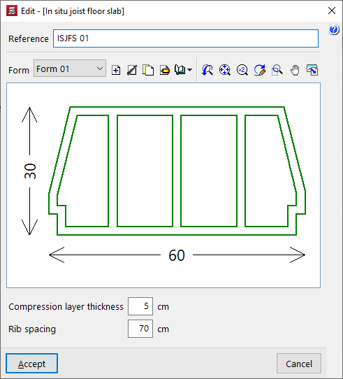
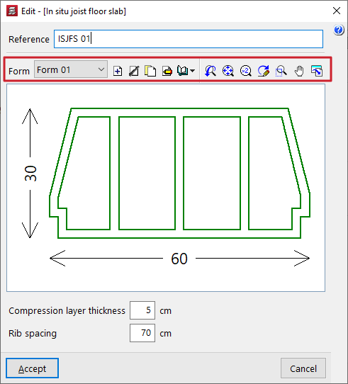
Defining in-situ concrete joist floors
The "In situ joist floor slab" option (within the "Enter floor" window, under "Joist floors") allows you to enter concrete joist floors that are assembled entirely on site.
The program will reinforce the joists on site in the same way as concrete beams. For this type of floor slab, you can assign base reinforcement for positive reinforcement using the option "Panels > Assign 'Base reinforcement / Welded mesh'".
When defining in-situ joist floors, the user must select the "Selected floor slab" from those available on site. The controls on the right allow you to "Add", "Delete", "Copy" or "Edit" these floor slabs.
When using these controls, the program opens a window where each joist floor slab can be configured on-site.
Here, a "Reference" is first entered for the floor slab.
Next, select the type of "Form" to be used in the floor slab. A designed section of the selected vault is displayed in the centre of the floor slab editing window.
Finally, the following parameters are defined:
- the "Compression layer thickness (a)";
- and the "Rib spacing (c)" between joists.
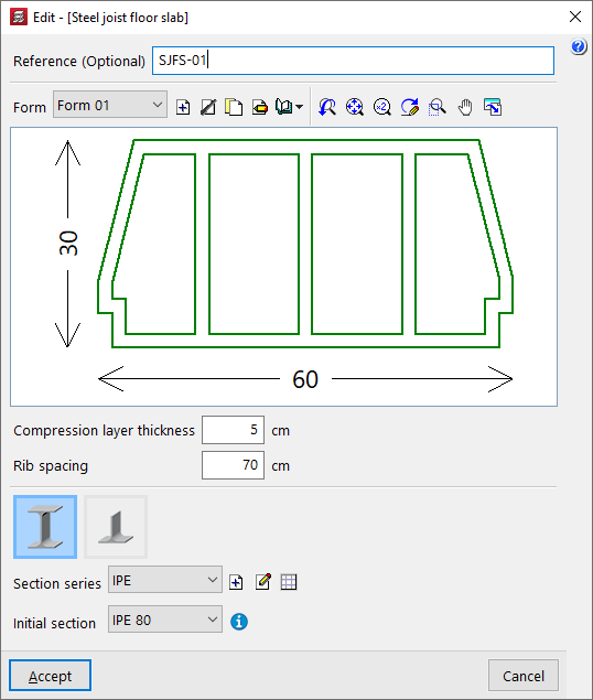
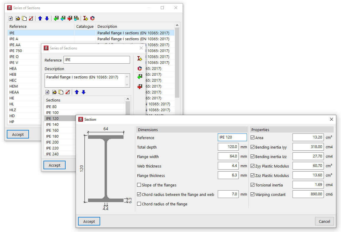
Defining steel joist floor slabs
When defining steel joist floor slabs (within the "Enter panel" window), the user must select the "Selected floor slab" from those available on site. The controls on the right allow you to "Add", "Delete", "Copy" or "Edit" these floor slabs.
When you use these controls, the program opens a window where you can configure each steel joist floor slab.
Here, a "Reference" is first entered for the floor slab.
Next, select the type of "Form" to be used in the floor slab. A designed section of the selected form is displayed in the centre of the floor slab editing window.
The following parameters are defined below:
- the "Thickness of the compression layer (a)";
- and the "Rib spacing (c)" between joists;
At the bottom, you can select whether the steel section to be used are of the "Double T" or "Single T" type. Next, the two drop-down menus at the bottom allow you to select the "Section series" to be used in the panel and the "Starting section" for the panel’s joists.
The controls to the right of "Section series" allow you to add, edit or manage the section series available in the project in a list.
In this list, as well as entering data manually and importing and/or exporting it to files on the hard drive, it is also possible to perform the "Import of predefined section series" from various catalogues and reference guides included in the program, as well as to download and "Import manufacturer catalogues" from the Open BIM Database.
Editing forms in cast-in-situ concrete and steel joist floor slabs
When defining floor slabs made of in-situ concrete joists or steel joists, you must select the type of "Form" to be used in the floor slab.
In the definition panel for these floor slabs, the controls to the right of the "Cavity" section allow you to "Add", "Delete", "Copy" or "Edit" the cavity types available on the project. It is also possible to access a menu of options under "Library Manager" to save information on the types of forms to files on the hard drive.
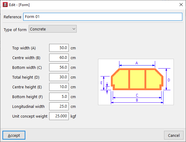
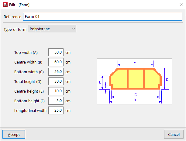
These controls open a window where you can configure each type of form by entering the following parameters:
- the "Type of form", whether "Concrete", "Ceramic", "Removable form" or "Polystyrene",
- and the geometric parameters that define it, which depend on the type chosen, including the various widths and heights, as well as its longitudinal width and unit weight, as applicable. The diagram of the form shown on the right helps to identify each parameter.
Concrete form / Ceramic form / Lightweight aggregate concrete form
The parameters required for the specification of concrete, ceramic or lightweight concrete blocks are as follows:
- Top width (A)
- Centre width (B)
- Bottom width (C)
- Total height (D)
- Centre height (E)
- Bottom height (F)
- Longitudinal width
- Unit concept weight
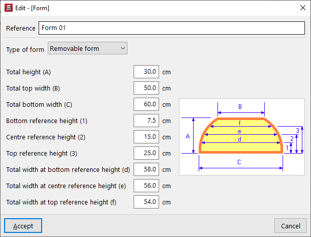
Removable form
The parameters required to define reusable formwork panels are as follows:
- Total height (A)
- Total top width (B)
- Total bottom width (C)
- Bottom reference height (1)
- Centre reference height (2)
- Top reference height (3)
- Total width at bottom reference height (d)
- Total width at centre reference height (e)
- Total width at top reference height (f)
Polystyrene form
The parameters required for defining polystyrene blocks are as follows:
- Top width (A)
- Centre width (B)
- Bottom width (C)
- Total height (D)
- Centre height (E)
- Bottom height (F)
- Longitudinal width
Defining joist floor slabs
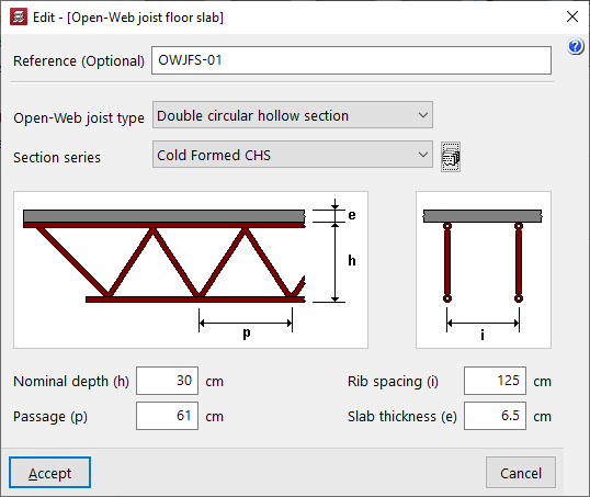
When defining simply supported latticed steel joists or joist floor slabs (within the "Enter slab" window), the user must select the "Selected floor slab" from those available in the project. The controls on the right allow you to "Add", "Delete", "Copy" or "Edit" these floor slabs.
When using these controls, the program opens a window where you can configure each joist floor slab.
Here, a "Reference (Optional)" is entered first for the floor slab.
Next, select the "Open-web joist type" from the available options:
- Double circular hollow section
- Double rectangular hollow section
- Quadruple rectangular hollow section
- Double angles
- Quadruple angles
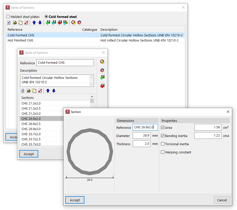
The drop-down menu at the bottom allows you to select the "Section series" used for the hollow sections or angles that make up the joist. The button on the right opens a window where you can select the type of steel and then add, edit and manage the section series available in the project in a list.
In this list, as well as entering data manually and importing and/or exporting it to files on your hard drive, you can also carry out the "Import of predefined profile series" from various catalogues and reference guides included in the programme, as well as download and "Import manufacturer catalogues" from the Open BIM Database.
Once the section series has been selected, the following parameters are defined:
- the "Total height (of the) lattice beams(h)";
- the spacing between the diagonals of the lattice ("Lattice spacing (p)");
- the "Rib spacing (i)" between joists;
- and the "Thickness (of the) top slab" (e).
These parameters (h, p, i, e) are shown in the designed diagram of the joist in the centre of the window.
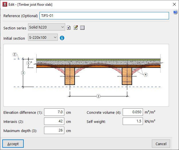
Defining timber joist floor slabs
When defining timber joist floor slabs (in the "Enter floor" window), the user must select the "Selected floor slab" from those available in the project. The controls on the right allow you to "Add", "Delete", "Copy" or "Edit" these floor slabs.
When you use these controls, the program opens a window where you can configure each timber joist floor.
Here, a "Reference (Optional)" is entered first for the floor slab.
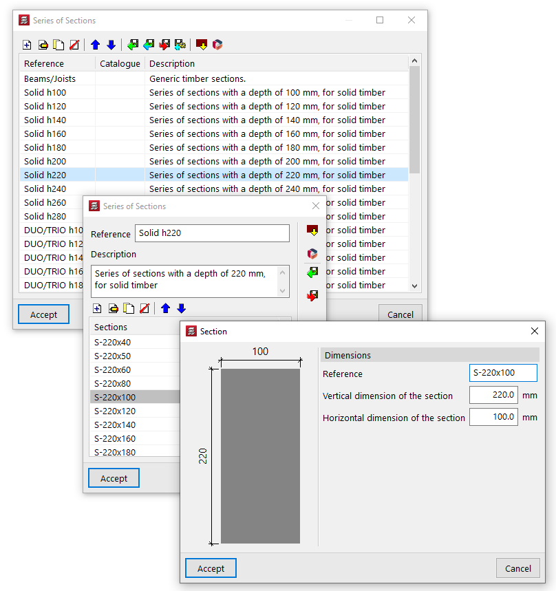
The two drop-down menus at the bottom then allow you to select the "Section series" to be used in the panel and the "Initial section" for the panel’s joists.
The controls to the right of the "Section series" area allow you to add, edit or manage the section series available in the project in a list.
In this list, as well as entering data manually and importing and/or exporting it to files on the hard drive, it is also possible to carry out the "Import of predefined section series" from various catalogues and reference guides included in the program.
Finally, the following parameters are defined:
- the "Elevation difference (1)" between the top surface of the joist and the reference level (Z);
- the "Interaxis (2)" between joists;
- the "Maximum depth (3)" of the floor structure, which includes the depth of the joists and that of the elements resting on them;
- the "Concrete volume (4)" used per unit area of the floor slab;
- and the value of the "Self weight" of the floor slab.
These parameters (1, 2, 3 and 4) are shown in the diagram of the timber joist floor structure in the centre of the window.
Inserting hollow core slabs
The "Hollow core slab" option, within the "Enter panel" window (accessible via "Slabs > Slab management"), allows you to enter prestressed precast slabs with lightening features or voids (hollow-core slabs).
Selecting hollow core slabs
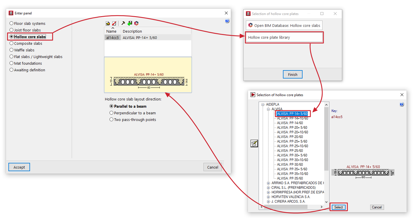
If you check the "Hollow core slabs" option without having previously selected a hollow core slab, the "Selection of hollow core slabs" window will open, displaying two options:
- Open BIM Database: Lightweight panels
This option allows you to download and update hollow core slab manufacturers’ catalogues from the Open BIM Database. When you do so, the "Edit hollow core slabs" window displays a list of products from the downloaded manufacturers, which can be "Imported" one by one into the project by checking the relevant option. When you click on "Finish", the imported manufacturer panels will appear in the panel list in the "Enter panel" window, ready to be selected and added to the model.
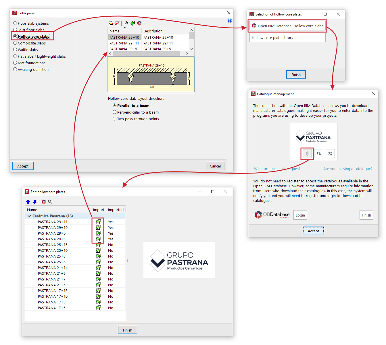
- Hollow core slab library
This option opens the "Selection of hollow core slabs" window, which displays the predefined hollow core slab libraries included with the software installation, as well as any user-created hollow core slab libraries.
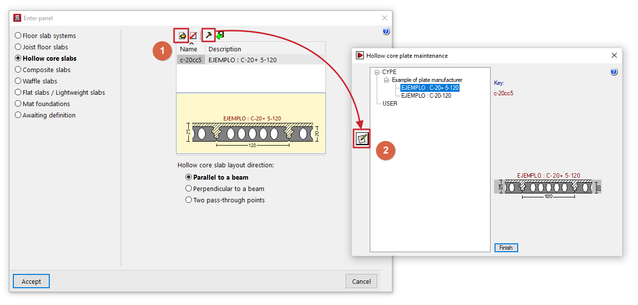
You can select a panel by expanding the tree to the relevant level. When you select a panel in the tree, the button on the left opens the "Edit hollow core slabs" window, which displays the technical properties of the selected panel. When you click on "Select", the selected panel will appear in the list of panels in the "Enter panel" window, ready to be selected and added to the model.
If panels have already been selected, the program will display a list of available panels in the "Enter panel" window, showing their "Name" and "Description". If you wish to import or create further panels, please use the controls at the top.
Maintenance of hollow core slab libraries
The "Enter panel" window displays a list of available hollow core slabs. The controls at the top of the list allow you to do the following:
- Edit
View the details of the panel selected from the list. For user library boards, you can edit their property values here. - Borrar
Elimina la placa seleccionada de la lista. - Edit library
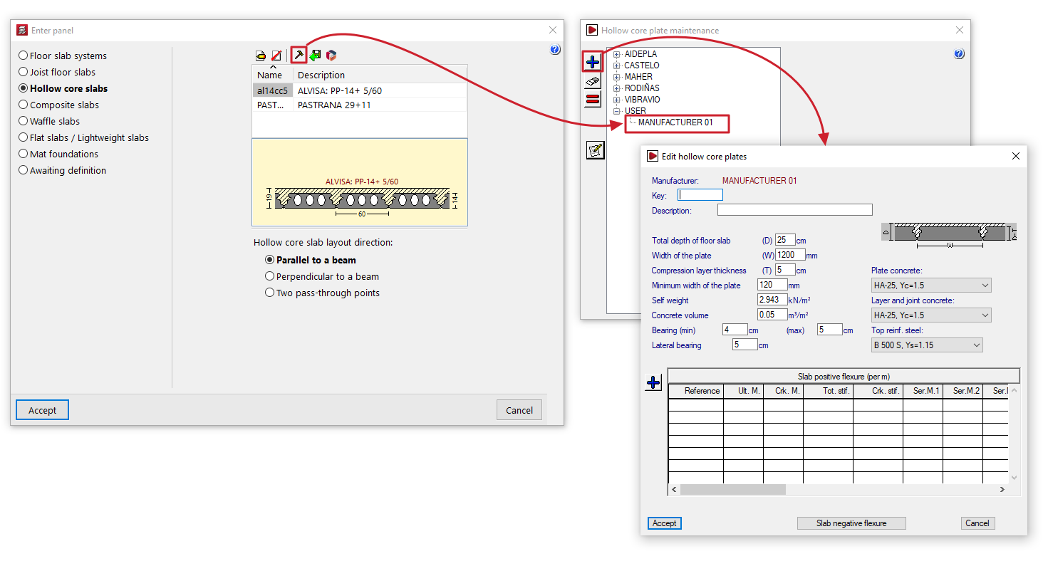
Opens the "Hollow core plate maintenance" window, where you can view the available manufacturer and user hollow core plate libraries. User plate libraries are managed from here:- To create user badges, first select "USER" from the tree and click the "+" button on the left-hand side. This creates an editable user. Next, select this user from the tree and click the "+" button again to create a badge, configuring all its settings.
- You can delete and/or copy user badges by selecting them from the list and using the relevant options on the left-hand side.
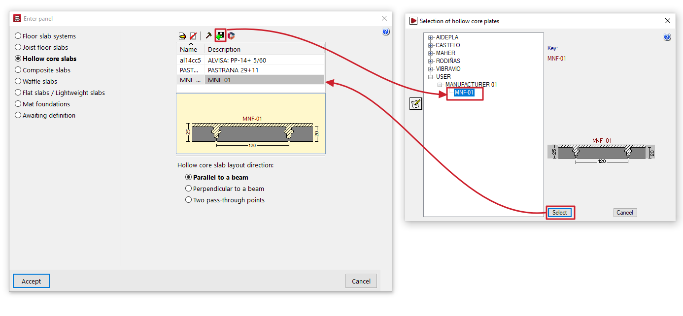
- Import from library
Opens the "Selection of hollow core slabs" window. This window displays the manufacturer hollow core slab libraries included in the software installation and the user panel libraries created via "Edit library". You can select any of the panels and click "Select" to import it into the panel list in the "Enter panel" window. - Import from 'Open BIM Database'
Opens the "Editing hollow core slabs" window, which displays the panels from the downloaded Open BIM Database catalogues, with the option to import them into the panel list in the "Enter panel" window.
The "Catalogue management" option at the top of this window allows you to download and update manufacturer catalogues from the Open BIM Database.
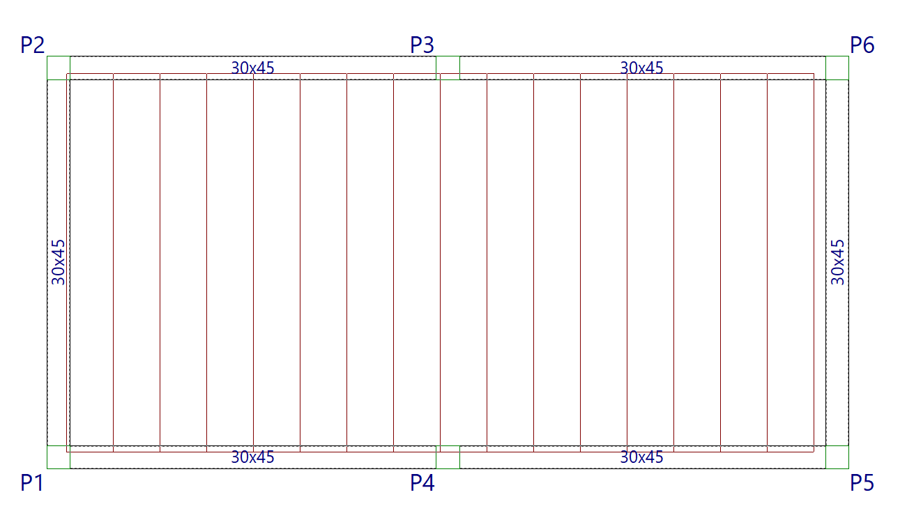
Additional options and on plan insertion
The program will display a designed diagram of the slab selected from the list.
At the bottom of the window, you can specify the "Hollow core slab layout direction". The options are:
- "Parallel to a beam" or "Perpendicular to a beam", to be selected by the user;
- or "Two pass-through points" may be marked on the floor plan to indicate the direction of the panels
Once you have accepted, moving the cursor over the various closed contours on the plan view will highlight the areas where the panel can be inserted. Then, click the left mouse button to insert the panel into that area.
Finally, using the left mouse button, you must select the beam or the connection points that define the direction of the slabs. The slab will be defined using this data and will be displayed on screen.
Editing hollow core slabs
The "Edit hollow core slabs" window (accessible via "Enter panel", "Hollow core slabs slabs", "Edit" (1), or via the edit button within "Maintenance of hollow core slabs" (2)) allows you to view or enter the geometric data and mechanical properties of the selected hollow core slab.
This window allows you to view information provided directly by the manufacturers included in the program (in the case of hollow core slab floor systems from the Open BIM Database catalogues or manufacturer libraries) or, in the case of user-defined hollow core slabs, to enter the values for a specific slab that you wish to prefabricate or construct on site.
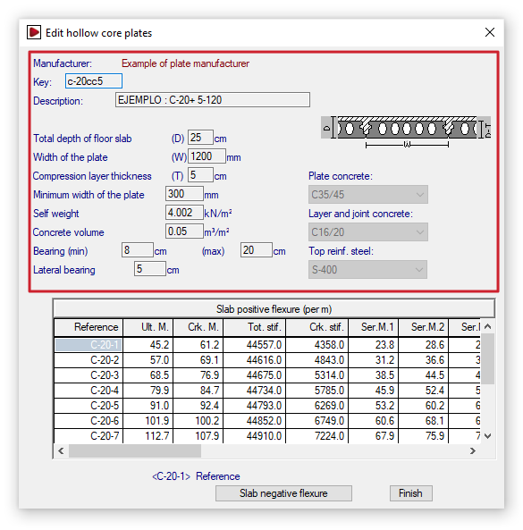
Defining the geometric and material properties of the plates
The geometric and material data provided by the program for each slab floor are as follows:
- Code
Identification of the plate tag using eight alphanumeric characters. - Description
Board name. - Total depth of the floor slab (C)
Total depth of the slab plus the compression layer, if any. - Width of the plate (A)
Plate width, or the distance between plates. - Compression layer thickness (E)
Thickness of the compaction layer, if any. - Minimum width of the plate
The minimum permitted width resulting from the longitudinal cut of a standard panel. Where a special panel of lesser width is produced, due to the dimensions of the panel section where it meets an edge, the width of this special panel must fall between the standard panel width and the aforementioned minimum permitted width. - Self weight
Weight per square metre of the complete floor structure. - Concrete volume
Volume of concrete in cavity fill, joints between slabs and the compression layer, if present. By default, the volume of the compression layer is used. - Minimum and maximum bearing
When the slab is offset from the normal to the support, the overhang differs at each edge of the slab and may vary between the minimum and maximum overhang values. If the maximum value is exceeded, the slab is chamfered. - Lateral bearing
This is the value by which the panel may deflect laterally when supported by a beam that is parallel to, or slightly offset from, the panel’s longitudinal direction. - Plate concrete / Layer and joint concrete / Top reinf. steel
This information is provided for reference purposes and indicates the materials used to calculate the section’s strength properties.
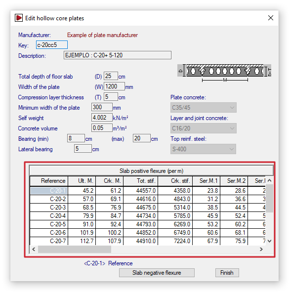
Entering the positive bending strength data for the plates
The structural data for the section are defined below:
- Positive bending of the floor slab (per metre)
This table is used to enter the structural data for the section under positive bending per metre of floor slab. The program allows you to define several slabs belonging to the same series. The following data is specified for each of them. This data corresponds to the section formed by the slab together with the joint-filling concrete and the compression layer, if present:- Reference
Reference number for each plate in the series. - Ultimate moment ("Ult. M.")
Maximum moment withstood (or ultimate moment). - Cracking moment ("Crk. M.")
Moment used to calculate deflection using the Branson method. - Total stiffness ("Tot. stif.")
Total stiffness of the composite slab-concrete section. This is used to form the stiffness matrix for the members into which the floor slab is discretised. - Cracked stiffness ("Crk. stif.")
Stiffness used to calculate deflection using the Branson method. - Service moments I, II and III ("Ser. M. 1", "Ser. M. 2", "Ser. M. 3")
Resisted moment according to the class in prestressed concrete:- Class I: structures in aggressive industrial or marine atmospheres, or in contact with aggressive soils or saline or slightly acidic water. This corresponds to Environment III.
- Class II: structures in normal, non-aggressive outdoor environments, or in contact with normal water or ordinary soil. This corresponds to Environment II.
- Class III: structures inside buildings or in outdoor environments with low humidity. This corresponds to Environment I.
- Ultimate shear ("Ult. S.")
The maximum shear force is withstood by the entire section, depending on whether the design moment (Md) is greater than or less than the unloading moment (Mg).
- Reference
If you are editing a panel record, the controls on the left allow you to add, delete or copy panels within the series.
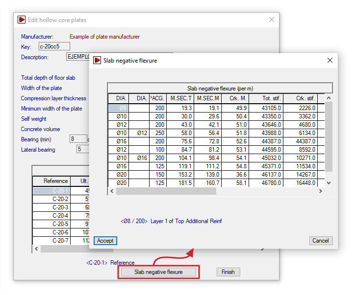
Entering the negative bending strength data for the slabs
Pressing the "Slab negative flexure" option at the bottom brings up the following table:
- Slab negative flexure (per metre)
This table is used to enter the structural data for the section under negative bending per metre of floor slab. It is possible to define different reinforcement combinations for each slab. Each row shows the mechanical characteristics of the section, taking into account that the load is distributed across the area subject to negative moments:- Diameter ("DIA.")/ Diameter ("DIA.") / Spacing ("SPACG.")
The two-diameter columns allow you to define two layers of top reinforcement with diameters that may differ. These reinforcement layers are arranged at the spacing specified in the third column. - Ultimate moment of the typical section ("M. SEC. T")
Negative moment withstood by the standard cross-section for the given reinforcement. - Ultimate moment of gross section ("M. SEC. M")
Negative moment withstood by the solid section for the given reinforcement. - Cracking moment ("Crk. stif.") / Total stiffness ("Tot. stif.") / Cracked stiffness ("Crk. stif.")
These parameters are used to calculate deflection using the Branson method. - Ultimate shear strength ("Ult. S.")
The maximum shear force that the section can withstand for the given reinforcement.
- Diameter ("DIA.")/ Diameter ("DIA.") / Spacing ("SPACG.")
As in the table above, if you are editing a panel’s record, the controls on the left allow you to add, delete or copy reinforcement combinations on the panel.
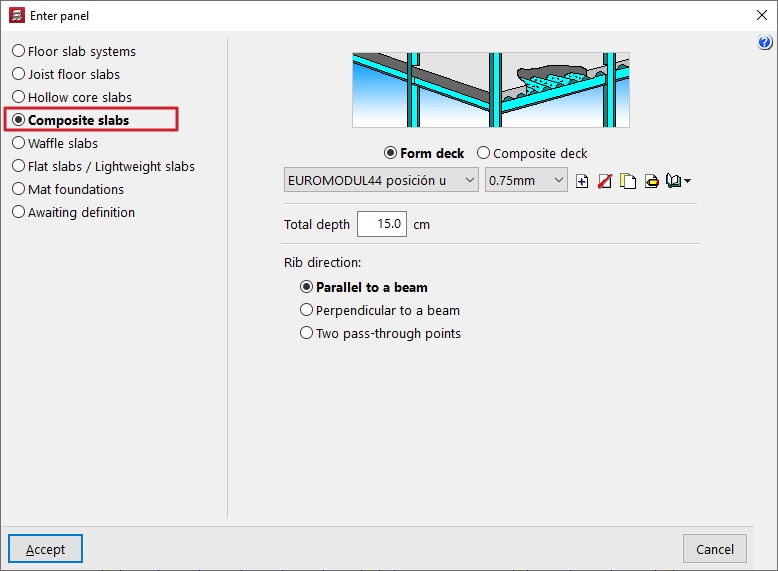
Inserting composite slabs
The "Composite slabs" option, within the "Enter panel" window (accessible via "Panels > Panel manager"), allows you to enter composite slabs made of sheet metal used solely as permanent formwork or as composite slabs.
Selecting the type of composite slab
The type of composite slab to be entered is selected using the options at the top of the "Enter panel" window:
- Permanent formwork
This option allows you to define composite slabs with non-load-bearing sheet metal:- During the construction phase, the sheet metal is used as permanent formwork. The sheet metal is capable of supporting its own weight, the weight of the fresh concrete and the construction loads on its own.
- During the service life, the sheet metal does not contribute to the structure’s load-bearing capacity; only the reinforced concrete slab provides structural support.
- Composite sheet metal
Allows you to define composite slabs using composite sheet metal:- During the construction phase, the sheet metal acts as permanent formwork.
- During service, the sheet metal is considered to form a structural bond with the hardened concrete, acting as tensile reinforcement and resisting positive moments in the finished floor slab. The sheet metal is capable of transmitting shear stresses at its interface with the concrete provided that mechanical interlocking is achieved through deformations in the sheet metal (notches or ridges).
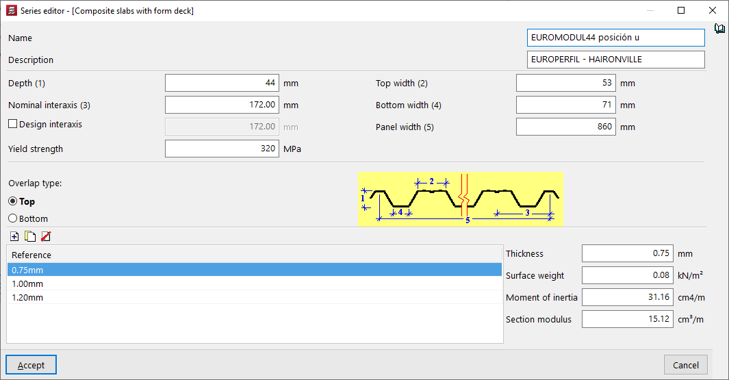
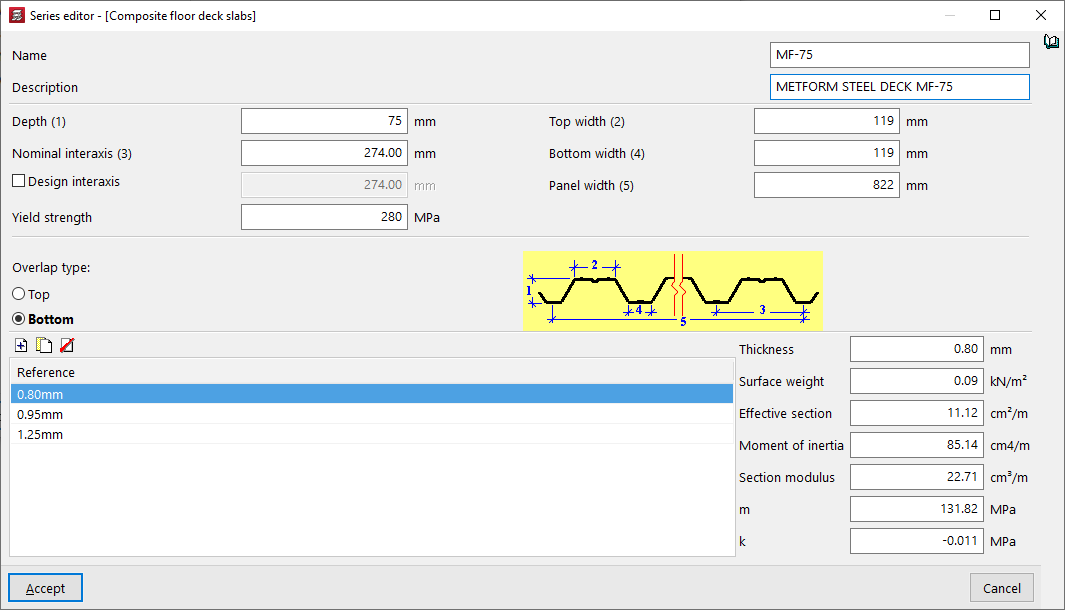
Editing and selecting ribbed sheets
Next, use the drop-down menus to select the type of ribbed sheet metal and the sheet thickness to be used in the composite slab.
The controls on the right allow you to "Add", "Delete", "Copy" or "Edit" the types of ribbed sheet metal available in the project. It is also possible to access a "Library Manager" options menu to save information on these types to files on the hard drive, both for composite slabs with sheet metal and permanent formwork, and for composite slabs with composite sheet metal.
The parameters required to define each type of ribbed sheet are as follows:
- the "Name" and "Description" of the type of badge;
- the parameters that define the geometry of the plate, such as its "Thickness", the "Top width" and the "Bottom width" of each rib, the "Nominal interaxis" between ribs and, optionally, the "Design interaxis", and the total "Panel width";
- the "Yield strength" of steel;
- the "Overlap type" between sheet metal panels, whether at the "Top" or "Bottom";
- and, at the bottom, the list of available sheet thicknesses, with their "Reference"; when selecting each one, the fields on the right allow you to enter the value of the "Thickness" of the sheet, the "Surface weight", the "Moment of inertia" and the "Effective section" of the sheet panel. Furthermore, for composite sheets, the "Section modulus" and the coefficients "m" and "k", provided by the sheet manufacturer, must be specified. To calculate the shear stress, the design value of the ultimate shear stress is determined, and this is partly a function of these coefficients.
Additional options and on-plan insertion
In the "Total depth" field, enter the total depth of the composite slab, including the thickness of the steel sheet and the thickness of the concrete compression layer.
At the bottom of the window, you can define the "Rib direction". These can be:
- "Parallel to a beam" or "Perpendicular to a beam", to be selected by the user;
- Alternatively, "Two reference points" can be marked on the floor plan to define the direction of the beams.
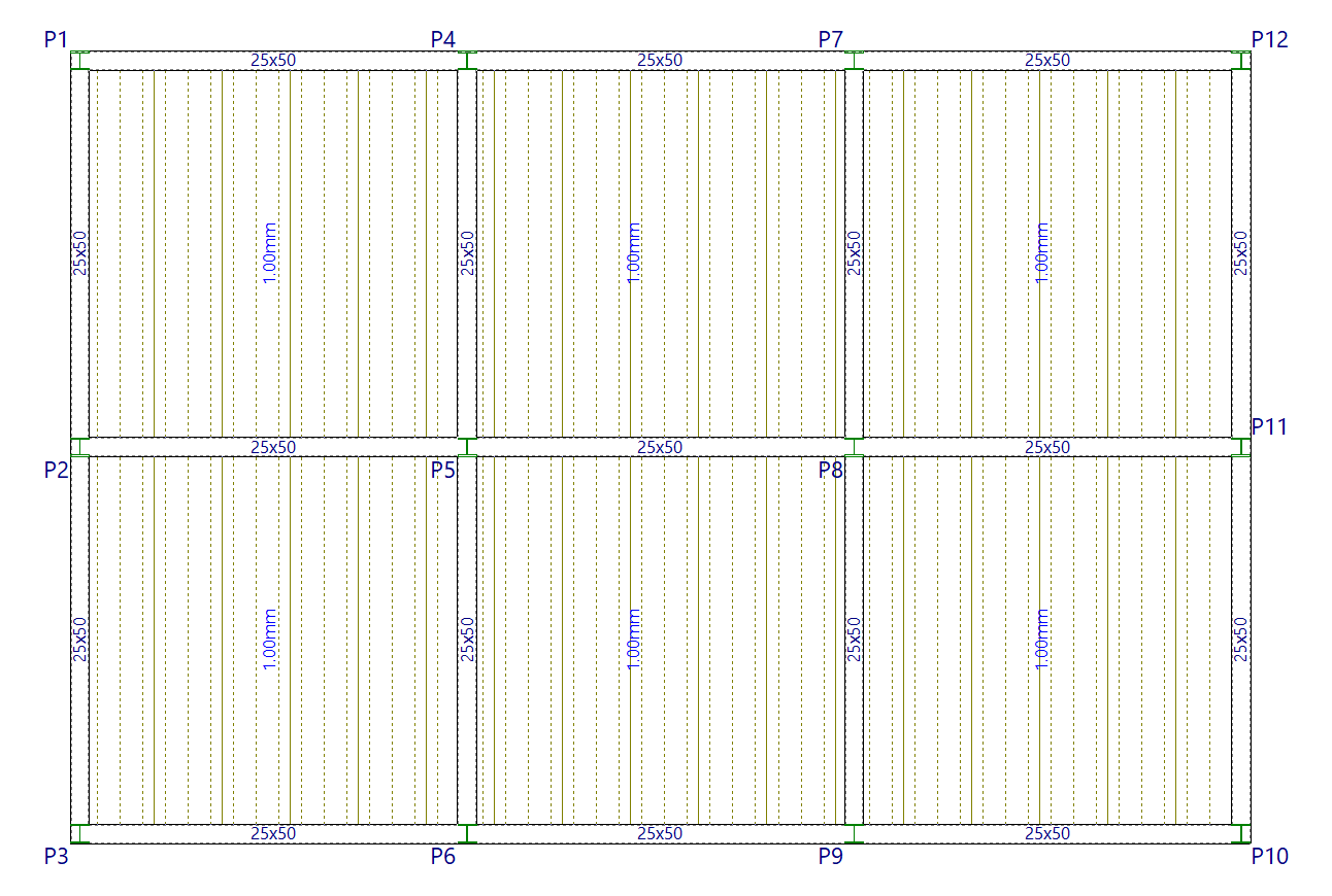
Once you have accepted, moving the cursor over the various closed contours on the plan view will highlight the areas where the panel can be inserted. Then, click the left mouse button to insert the panel into that area.
Finally, using the left mouse button, you must select the beam or the connection points that define the direction of the ribs. The panel will be defined using this data and will be displayed on screen.
Inserting waffle slabs
The "Waffle slabs" option, within the "Enter slab" window (accessible via "Slabs > Panel manager"), allows you to enter lost or removable forms.
Creating and editing waffle slabs
When selecting the "Hollow core slabs" option, you must first specify the "Type of form". This can be "Lost" or "Removable".
Next, the list of available waffle slabs for the selected form is displayed, showing their "Name", "Material" and "Description". The controls at the top of the list allow you to do the following:
- Add
Adds a new waffle slab of the selected type to the list. After entering the name and confirming, you must enter the parameters that define the slab in the pop-up window. - Edit
Allows you to edit the values that define the selected floor slab. Any changes will only affect the floor slab defined in the current project. If you wish to copy it to the library, you must confirm the dialogue box that appears. - Delete
Removes the selected floor slab from the list.
| Note: |
|---|
| If you access this option without having previously selected a waffle slab, a window will open allowing you to import data from the Open BIM Database or from the libraries of permanent or removable waffle slabs available by default in the program. |

Waffle slab libraries
The following controls at the top of the list of waffle slabs enable the management of libraries for this type of slab:
- Import from library
Opens the "Lost forms library" or "Removable forms library" window. This window displays the libraries of waffle slabs included in the software installation, along with the slabs added in the "Enter panel" window and exported via "Export to library". You can select any of the slabs and click on "Import" to import it into the list of waffle slabs in the "Enter panel" window. - Export to library
Allows you to export the selected slab to the library of waffle slabs of the corresponding type.

Creating and editing waffle slabs with lost form
When creating or editing a waffle slab with lost form, you must specify the following details:
- the "Reference" of the floor slab;
- the "Material" used for the lightweighting, whether "Concrete", "Lightweight concrete", "Ceramic" or "Polystyrene";
- the "Nº of elements" that make up the panel, whether one, two, three, four or six pieces;
- and their "Geometric data", which may be "Same in X and Y" or "Different in X and Y":
- the "Total depth (h)",
- the "Compression layer (c)",
- the "Rib spacing (b)" and the "Rib width (a)" in both directions or in the "X-direction" and the "Y-direction", depending on the option selected.
- The diagram on the right shows the values a, b, c and h to make it easier to understand.
- Alternatively, you can also enter the value for the "Concrete volume" to be used and the "Self weight" per unit area directly.

Creating and editing waffle slabs with recoverable form
When creating or editing a waffle slab with recoverable form, you must specify the following details:
- the "Reference" of the floor slab;
- if "Half form available" (this box is ticked if the floor slab being edited allows the use of reusable formwork of half-block size);
- and their "Geometric data", which may be "Same in X and Y" or "Different in X and Y":
- the "Total depth (h)",
- the "Compression layer (c)",
- the "Rib spacing (b)", the "Rib width (a)", and the "Heights" and "Widths" of the ribs ("h1", "h2", "h3", "a1", "a2", "a3" and "a4") that define its cross-section, in both directions or in the "X-direction" and the "Y-direction", depending on the selected option.
- The diagram on the right shows the values a, b, c, h, h1, h2, h3, a1, a2, a3 and a4 to make it easier to understand.
- Alternatively, you can also enter the value for the "Concrete volume" to be used and the "Self weight" per unit area directly.

Waffle slabs from the Open BIM Database
The "Import from 'Open BIM Database'" option at the top of the waffle slab list opens a window displaying the waffle slabs from the downloaded Open BIM Database catalogues.
The "Catalogue management" option at the top of this window allows you to download and update manufacturers’ catalogues from the Open BIM Database. Once you have done so, the list will display the products from the downloaded manufacturers, which can be "Imported" individually into the project by ticking the relevant option.
When you click on "Finish", the imported slabs will appear in the slab list in the "Enter panel" window, ready to be selected and added to the model.

Additional options and on-plan insertion
The program will display a designed diagram of the waffle slab selected from the list.
The "Direction of the longitudinal ribs" is defined at the bottom of the window. These can be:
- "Parallel to a beam" or "Perpendicular to a beam", to be selected by the user;
- Alternatively, "Two reference points" may be marked on the floor plan to define the direction of the longitudinal ribs.
Once you have accepted, moving the cursor over the various closed contours on the plan view will highlight the areas where the panel can be inserted. Then, click the left mouse button to insert the panel into that area.
Finally, using the left mouse button, you must select the beam or the reference points that define the direction of the longitudinal ribs. The panel will be defined using this data and will be displayed on screen.
Later on, you can automatically generate the drop panels for each panel of the waffle slab using the "Drop panels > Generate drop panels" in the "Panels" menu, and a base reinforcement can be assigned via "Assign 'Base Reinforcement / Welded Mesh'", also in the same menu.

Entering solid slabs, mat foundations and panels awaiting definition
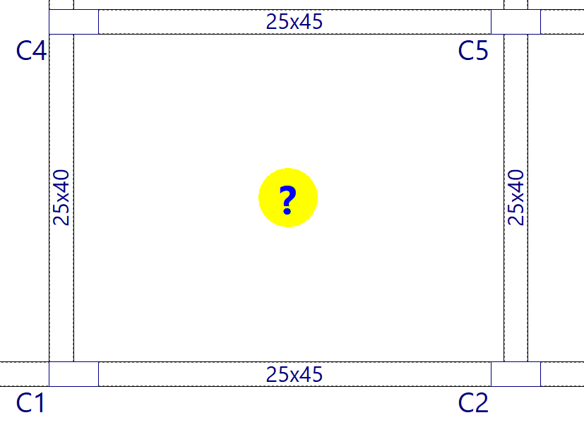
Definition of the panels outline
In order to insert any floor slab, you must first draw a closed outline of beams and/or walls using the "Insert beam" or "Insert wall" options.
At this point, a question mark on a yellow circle will appear on the screen in the geometric centre of the panel. This means that the outline has been entered correctly and that the panel is pending definition.
Entering slabs
Once the outline of the floor slab has been defined, to insert it, select the "Panel manager" option from the "Slabs" menu. This menu is available in the "Beam input" tab.
Then, in the menu that appears, select the option "Enter panel".
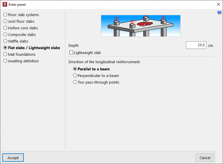
In the next window, select the type of floor slab from those offered by the program:
- Floor slab systems
- Joist floor slabs
- Hollow core slabs
- Composite slabs
- Waffle slabs
- Flat slabs / Lightweight slabs
- Mat foundations
- Awaiting definition
The options for entering flat slabs, mat foundation, and panels to be defined are described below.
Flat slabs
To introduce a solid slab, select the option "Flats / Lightweight slabs" and keep the box "Lightweight slab" unchecked.
Solid slabs are discretised as a mesh of bars during the analysis.
For solid slabs, the programme only requires the definition of their "Depth". The "Direction of the longitudinal reinforcement" must also be selected, which can be "Perpendicular to a beam" selected on the floor plan, or by entering "Two pass-through points".
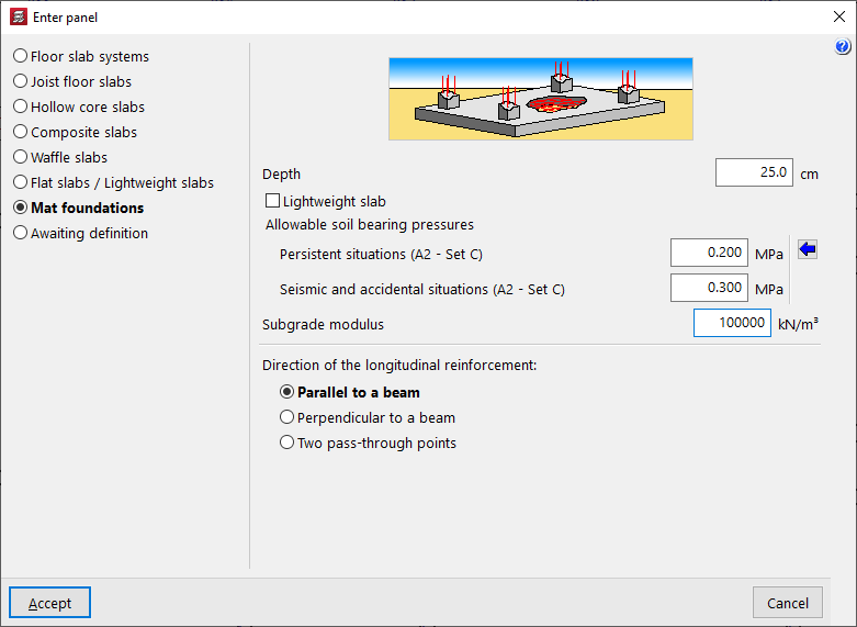
Mat foundation
The following option allows you to enter "Mat foundations".
These elements, like solid slabs, are also discretised as a mesh of bars, adding elastic external connections at their intersections to simulate support on the ground.
In addition to the "Depth" and the "Direction of longitudinal reinforcement", the value of the subgrade modulus must be indicated, which will influence the rigidity of these connections, as well as the "Allowable soil bearing pressures" in "Persistent situations" and in "Seismic and accidental situations". You can "Import usual design values" using the button on the right.
| Note: |
|---|
| Pillars that start on a slab supported on the ground must be defined as "No external connection". |
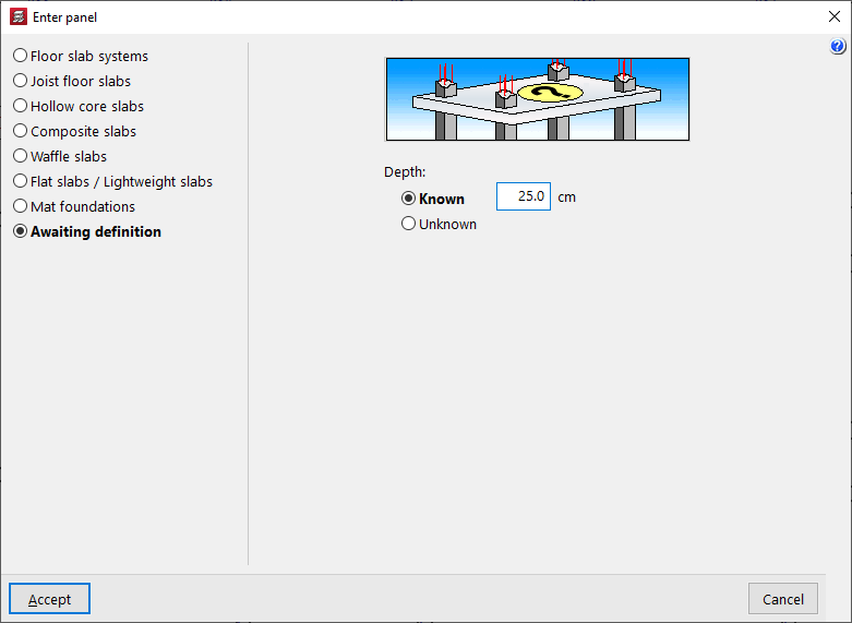
Panels awaiting definition
The "Awaiting definition" allows you to keep a panel without completing its definition, indicating only whether the "Depth" is "Known" or "Unknown".
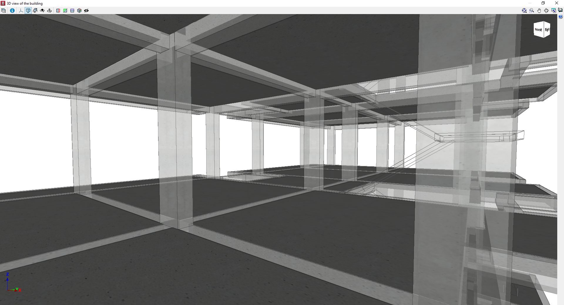
These types of panels are included in the 3D view of the project; furthermore, it is possible to assign them to inclined plans and establish their slope in relation to the floor plan. However, the program will not allow the project to be analysed until the characteristics of all the panels have been fully defined.
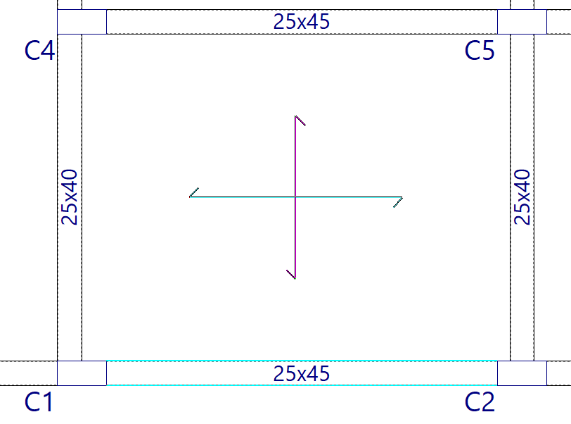
Layout of the panel on the floor plan
After accepting the panel, click on the floor plan. If necessary, define the direction of the reinforcement by clicking on a beam or selecting two points, depending on the option previously chosen.
If entered correctly, the program will display the symbol for the panel entered. For example, for solid slabs, the corresponding symbol is two lines crossed in the centre of the slab.
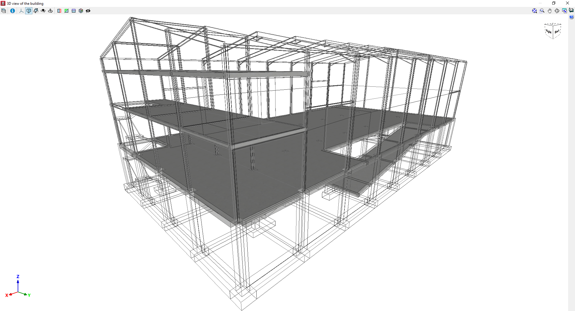
Examples of models with solid slabs
Inserting, editing and generating drop panels
The "Drop panels" option, within the "Enter panel" window (accessible via "Panels > Panel manager”), opens a menu with various options for entering, editing and automatically generating drop panels in waffle slabs (defined as such under “Enter panel > Drop panels”).

They are as follows:
- Configuration of drop panel generation
- Generate drop panels
- Enter drop panels
If tables have been entered or generated in the floor plan, the following options are available:
- Move corners
- Delete a drop panel
- Delete drop panels of a slab
- Delete all drop panels

Configuration of drop panel generation
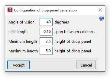
This option allows you to configure the following settings for the automatic generation of drop panels:
- Angle of vision
The program generates two views in the directions of the mesh passing through each column centre. For each view, an angle of vision is then set, the value of which is specified in this option (ranging from 10 to 60 degrees; the default is 40 degrees). From then on:- If another column falls within the field of view, the distance to that column will be used as the reference distance for generating the table.
- If there are several columns within the angle, the nearest one will be selected.
- If there are no columns within the angle, the drop panel shall be designed to the "Minimum length".
- Solid section length
The dimension of the drop panel in each direction corresponds to the length of the solid section, measured from the face of the column to the outer edge of the drop panel. This length is calculated as a percentage of the distance between the column in question and the nearest column within the angle of view. This value ranges between 0.10 and 0.30 (default: 0.16) of the span between piers. - Minimum length
The minimum length of the drop panel is used when there is no other column within the field of view; it is measured from the face of the column to the outer edge of the drop panels, relative to the edge of the drop panels. This value must be between 1 and 3 (default: 2.5) times the height of the drop panel. - Maximum length
This value determines the maximum length of the drop panel and is measured from the face of the column to the outer edge of the drop panel, relative to the edge of the drop panel. This value must be between 3 and 6 (default: 5) times the height of the drop panel.
Generate drop panels
The "Generate drop panel" option automatically creates all the drop panels for the floor slabs on the floor plan in accordance with the defined "Configuration of drop panel generation".
New drop panels are only generated on columns that do not already have them; therefore, this option does not restore their original dimensions unless they are first removed using the relevant options.
The geometry of the generated drop panels can be edited later using the other options.

Enter drop panels
The "Enter drop panel values" option allows you to enter the drop panel value for a column by clicking on it.
If, instead of selecting a column, you click on another point on the slab, you can solidify an area of the slab by selecting the two corners of the rectangle that defines it.
| Note: |
|---|
| When defining the geometry of the drop panel, it is possible to solidify only a portion of the "Number of elements" used for lightening that make up the form (in permanent coffered slabs) or half form slab, if the slab has a "Half form available" (in removable form slabs). These options are available in the waffle slab editing panel. |

Move corners
The "Move corners" option allows you to modify the geometry of the drop panel.
To do this, select a corner of the drop panel, then move the corner to its new position, thereby simultaneously adjusting two sides of the drop panel’s edge.

Clear a drop panel
The "Delete a drop panel" option allows you to delete a drop panel by clicking on it.
If two or more drop panels are joined together, they must be removed one by one. If a drop panel is divided by a beam, each surface of the drop panel must be marked on each slab.
Clear the drop panel from the board
The "Delete drop panels of a slab" option allows you to simultaneously remove all drop panels from the waffle slab selected on the floor plan, defined as a closed outline bounded by beams.
Clear all drop panels
The "Delete all drop panels" option removes all drop panels from the waffle slabs on the current floor.

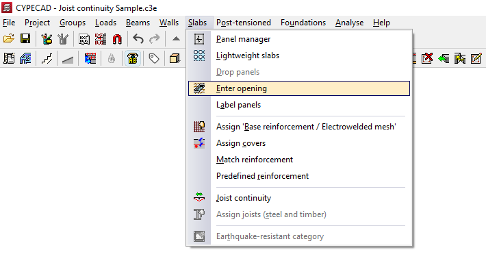
Creating openings in floor slabs using a perimeter of beams
The "Enter opening" option, located in the "Panels" menu on the "Beam input" tab, allows you to automatically generate a rectangular perimeter of beams that form an opening in the floor plan.
| Note: |
|---|
| This option should not be confused with "Delete panel (enter opening)" in the "Panel Manager" menu, which allows you to define an empty opening in a section of the floor plan based on the outline of previously entered beams. |
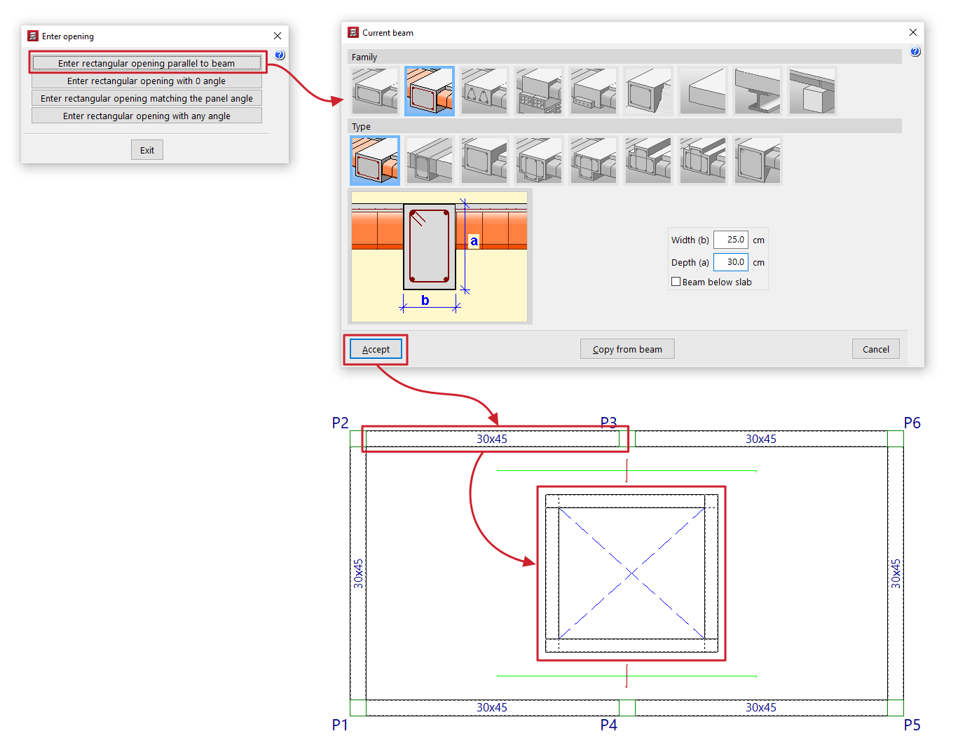
When you click on this option, a dialogue box appears with the following options:
Enter rectangular opening parallel to beam
When you click this option, the “Current beam” window opens first, where you can specify the type of beam to be used as the edge of the opening.
Next, the user must select an existing beam, to which the beams of the generated rectangular opening will be parallel and perpendicular. Finally, two points must be marked on the plan view, which will form one of the diagonals of the opening.
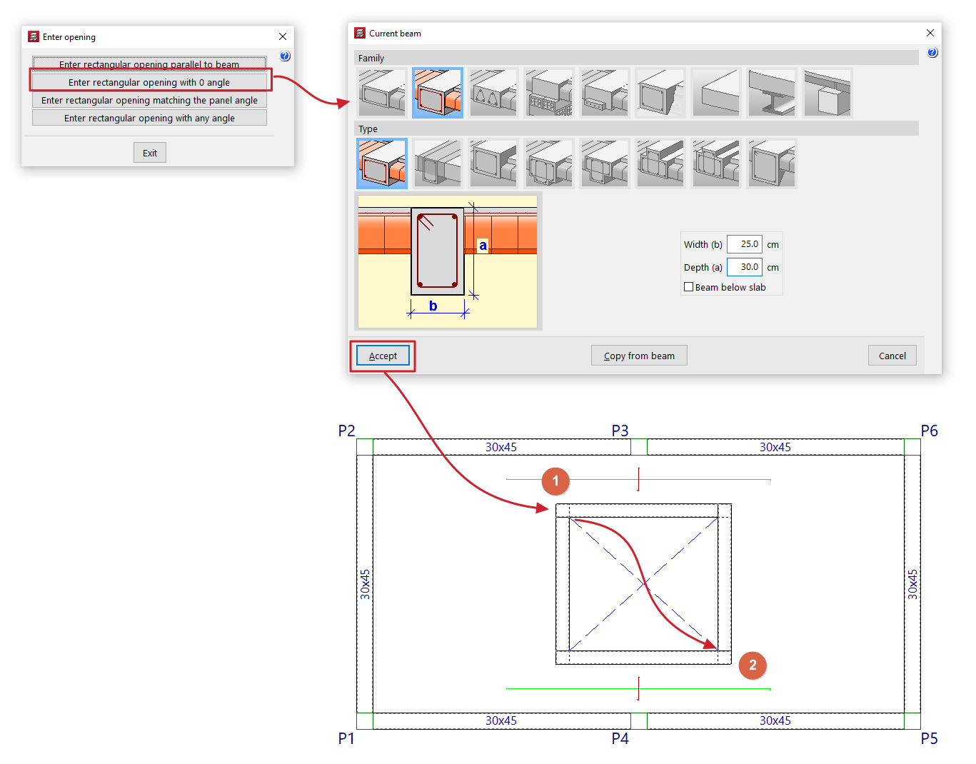
Enter rectangular opening with 0 angle
When you click this option, the “Current beam” window opens first, where you can specify the type of beam to be used as the edge of the opening.
Next, mark two points on the floor plan, which will form one of the diagonals of the opening. The beams will follow the directions of the main coordinate axes.
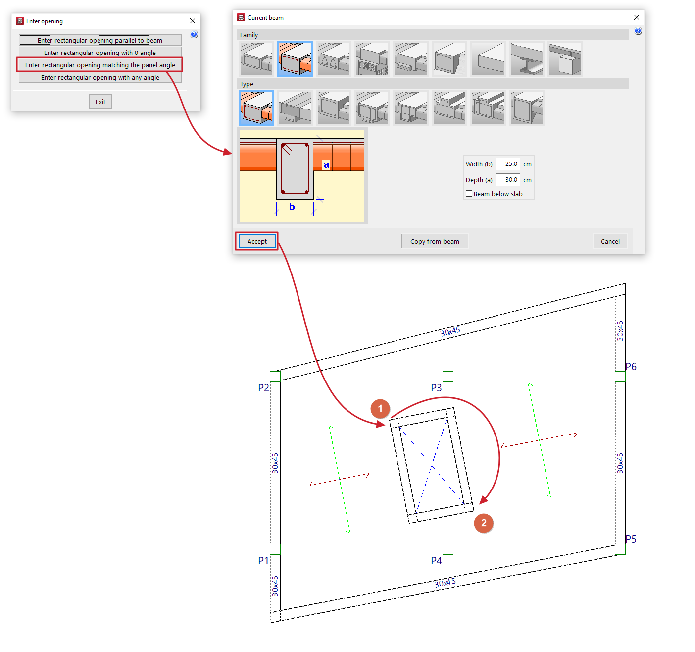
Enter rectangular opening matching the panel angle
Al pulsar esta opción, se abre en primer lugar la ventana “Viga actual”, donde se define el tipo de viga que se utilizará como borde del hueco.
Next, mark two points on the floor plan, which will form one of the diagonals of the opening. The beams must be parallel and perpendicular to the direction of the ribs in the floor slab section where the opening is to be created. If the section where the opening is to be created is unloaded, the new opening is generated with its sides parallel to the main coordinate axes.
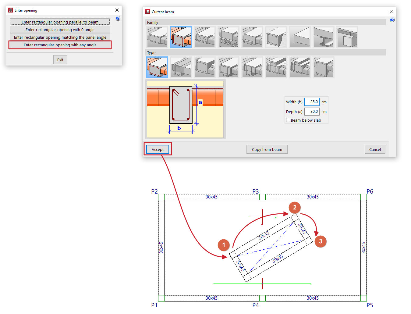
Enter rectangular opening with any angle
When you click this option, the “Current beam” window opens first, where you can specify the type of beam to be used as the edge of the opening.
Next, mark two points to define one side of the opening and, finally, a point to define the opposite side.
Label panels
The "Label panels" option, within the "Panels" menu on the "Beam input" tab, allows you to change the label of joist floor slabs or panels. It also allows you to change the position of the reference for any type of panel.
The panel references can be displayed via "Groups > Visible references".
To do this, in the pop-up window that appears when you click on "Label panels", do the following:

- To change the references for the panels in a joist floor slab, select "References" and enter the desired reference in the corresponding field. Then, click "Assign" and select the panels on the floor plan to which you wish to apply this reference.

- To modify the references for flat slab panels, select "Nº Slabs" and, in the "Flat slabs" section, enter the "Flat slab number", which defines the numbering of the first slab selected subsequently. Then, click on "Assign" and sequentially select the flat slab sections on the floor plan that you wish to number consecutively, starting from the number indicated.

In the above cases, the points marked on the floor plan will determine the position of the sign on each section.
In any case, you can also click on the "Modify position" option to change the position of the label on any panel. To do this, click on the panel in the floor plan and then select the point where you want to place the label text.
The pop-up window also allows you to "Delete" the reference entered using this tool in the panels of the selected floor type ("Beams" or "Flat slabs"), or "View" the floor plan, by right-clicking to bring up the pop-up window again.

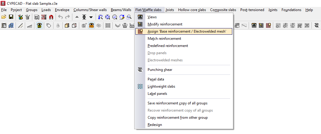
Assigning base reinforcement or electrowelded mesh
The option "Assign 'Base reinforcement / Electrowelded mesh'", available in the "Panels" menu on the "Beam input" tab and also in the "Slabs/Waffle slabs" menu on the "Results" tab, allows you to define base or assembly reinforcement for drop panels, slabs, waffle slabs, in-situ joist floors and composite slabs, as well as welded mesh for slabs.
When you click on the option, if there is more than one type of slab on the current floor, you must select a floor slab using the left mouse button to specify the reinforcement type to be assigned:
- In the case of solid slabs, you will need to choose whether to assign a "Base reinforcement" or an "Electro-welded mesh" by selecting the relevant option in the window that appears.
- In all other cases, the program will allow you to assign a "Base reinforcement".
For analysis purposes, the welded mesh and the base reinforcement are treated in the same way, bearing in mind that, when designing the slab reinforcement, both elements provide a uniform mechanical contribution across the entire span.
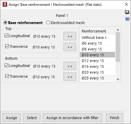
Assignment of base reinforcement
To assign a base framework, you need to configure the following options in the window that appears when you select this option:
- On the left, tick the boxes for the reinforcement types you wish to apply ("Longitudinal" or "Transverse", and either "Top" or "Bottom").
- The "Assemblies" column on the right shows the available base assemblies according to the assembly table that has been configured.
- Using the buttons in the middle (labelled "< <"), you can copy the selected reinforcement on the right to the sections corresponding to the top longitudinal, top transverse, bottom longitudinal and bottom transverse reinforcement on the left. You must click on each of these buttons for every position of the reinforcement, if there are several.
| Note: |
|---|
| If you wish to assign a standard reinforcement configuration that is not available in the table, you must edit the relevant reinforcement table (under "Project > General data > By position") and add that configuration. In the case of drop panels, the minimum reinforcement required for the top-mounted reinforcement is 2∅10 per grid. For this reason, when a lower value, 2∅8, is selected in the reinforcement list, the buttons allowing it to be assigned to the top reinforcement do not appear. Furthermore, for foundation slabs, it is mandatory to place a base reinforcement based on the slab thickness. Consequently, base reinforcement configurations below those defined based on the thickness of the selected foundation slab will not be available. These values can be modified in the program under "Project > General data > By Position > Flat, waffle and joist floor slab options > Minimum quantities". |
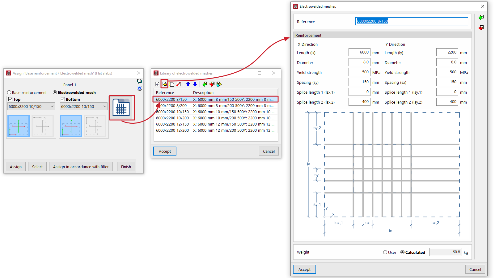
Assigning welded mesh
To assign welded mesh to a solid slab, the window that appears when you select this option allows you to specify the welded mesh to be assigned to both the "Top" and "Bottom" faces of the slab. To do this:
- Select one of the welded mesh options available from the drop-down menu. If you wish to assign a welded mesh that is not listed in the table, you will need to edit the "Welded mesh library" accessible on the right-hand side and, if necessary, modify the welded mesh assembly tables.
- At the bottom, you can specify whether the X and Y axes of the mesh are "Coincident axes" with the slab’s reinforcement axes, or "Transposed axes" (rotated by 90° relative to the slab’s reinforcement axes).
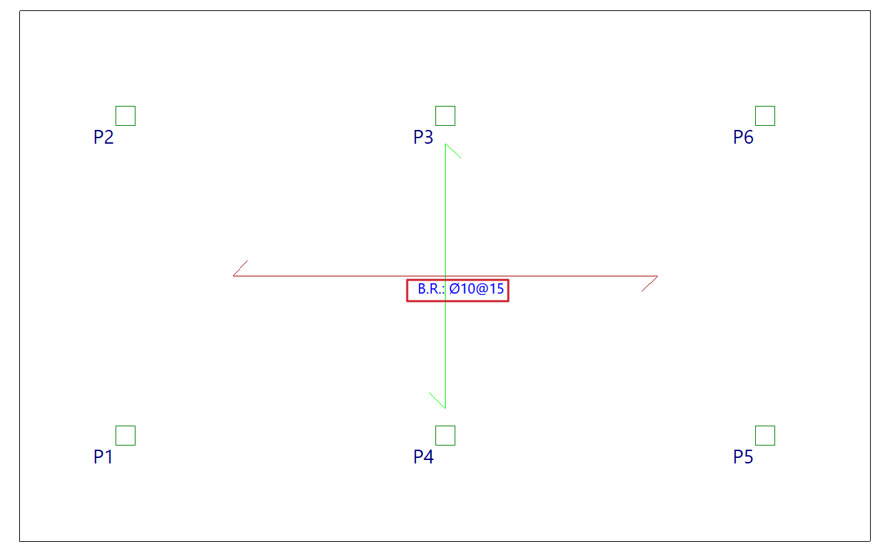
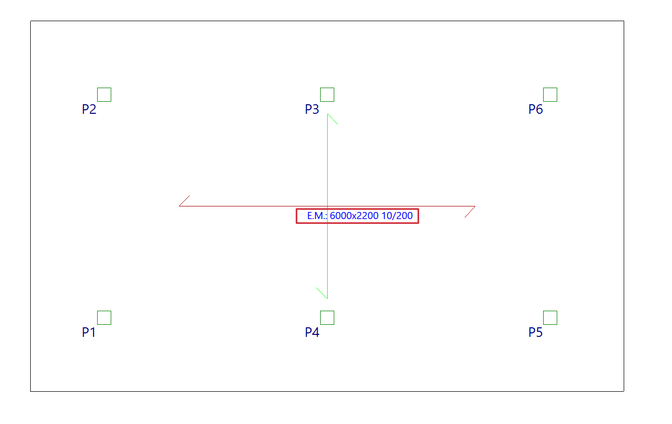
Selecting panels on the floor plan
Once you have defined the base reinforcement or welded mesh to be assigned, click on "Assign" and select the floor panels to which you wish to apply it on the floor plan. If you select a panel of a different type, you will be prompted again to select the base reinforcement to be assigned to panels of that type.
The "Select" option allows you to extract information about the base reinforcement or welded mesh from a panel where it has already been applied.
Furthermore, the "Assign according to filter" option allows you to assign the specified base reinforcement or welded mesh to the panels selected according to the defined filter. The filter can be applied to the "Current group", to "All groups" or to a "Selection of groups". In the list that appears when using this option, you must tick the "Assign" box for the slab types to which you wish to apply the base reinforcement or welded mesh.
Once the base reinforcement or welded mesh has been applied to the panels, you can re-reinforce the slabs via the "Reinforce slabs" option, which is available under the "Match reinforcement" option in the same menu.
Assigning specific covers for each floor slab
The "Assign covers" option, within the "Slabs" menu on the "Beam input" tab, allows you to assign covers to slabs that are either the same as or different from those entered in the general project data.

To do this, after clicking on this tool, you can choose one of the following options:
- If you select "General project data", the program will use the data entered under "Project > General data > By position > Common options for bars > Overlaps".
- If you select "Specific for the panel, you will need to specify the required cover depth for the selected slab.
This is possible for all panel types for which finishes can be defined:
- In waffle slabs and flat slabs, the top and bottom geometric and mechanical cover thicknesses are specified,
- In joist floors and composite slabs, the top, bottom and side covers are specified,
- and for lightweight panels, mechanical fastening is specified.
Next, click on "Assign" and select the panels on the floor plan to which you wish to assign the data. In the pop-up window, you can also use the "Select" option to copy the data from a selected panel on the floor plan, "Assign to all" to assign the data to all panels on the floor plan, or "Cancel" to close the window.
Further on, in the "Project data list", under the "Cover" section, the various cladding options defined for the facades will be shown, where applicable.

Matching reinforcement for slabs and waffle slabs
The "Match Reinforcement" option, available in the "Panels" menu on the "Beam input" tab and also in the "Slabs/Waffle slabs" menu on the "Results" tab, allows you to enter alignment lines or rectangles that unify the reinforcement of slabs and waffle slabs obtained after the analysis.
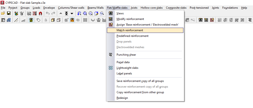
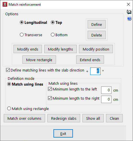
In the "Match reinforcement" window that appears when you click this option, the program offers various operations for aligning the reinforcement in grid slabs or flat slabs:
- Options
- Longitudinal / Transverse / Top / Bottom
This allows you to specify the type of reinforcement you wish to match, whether longitudinal or transverse, on the top or bottom face of the slab. - Modify ends
Moves one end of an alignment line or rectangle whilst keeping the other end fixed. If the "Define matching lines with the slab direction" checkbox is deselected, you can rotate the alignment line by dragging the selected end. - Modify lengths
Changes the minimum lengths of the alignment lines or rectangles entered. If the minimum length options are enabled and defined, they are replaced by the new lengths. If they are not, you must set the desired length by dragging the lines parallel to the main line with the cursor. - Modify position
Changes the position of the alignment line within a rectangle. - Move rectangle
Changes the position of an alignment rectangle. To do this, left-click to select it and drag it to its new position. - Extend ends
Lengthens or shortens the position of the ends of alignment lines and rectangles.
- Longitudinal / Transverse / Top / Bottom
- Enter
After selecting the type of assembly to align and the alignment mode, this allows you to insert alignment lines or rectangles on the floor plan. - Delete
Allows you to delete previously entered alignment lines or rectangles. To do this, go to "Options" and select the assembly in which you entered those lines or rectangles, then select the alignment lines or rectangles on the floor plan using the left mouse button. - Enter levelling lines with slab direction + 'X'º
If you wish to enter a levelling line at any angle, deselect this box. If you wish to set a specific angle, tick this box and specify the angle to be applied. If this box remains ticked with a value of 0°, as is the default, alignment lines can only be entered in the main directions of the slab. - Input mode
Allows you to select whether alignment is performed by lines or by rectangles:- Match using lines
This allows you to enter an alignment line. The procedure is as follows: after selecting the type of reinforcement to be aligned in the "Options" section of this window, click the "Enter" button. Next, enter the alignment line in plan view by marking its start and end points, ensuring it is perpendicular to the reinforcement ribs or bars to be aligned, and extending from the first to the last rib or bar to be aligned. All bars intersected by this line will be aligned when the "Reinforce slabs" option is used.- Min. length on the left / Min. length on the right
If you wish to align the line by adding minimum lengths on both sides of the alignment line, tick these boxes and enter the lengths in centimetres. If you prefer to mark these lengths on the plan, deselect these checkboxes and press "Enter"; then mark the two end points of the line, followed by two points on the plan to define the left and right lengths. This is a way of creating an alignment rectangle.
- Min. length on the left / Min. length on the right
- Rectangular bracing
Allows you to enter a bracing rectangle. The procedure is as follows: after selecting the type of bracing to be entered in the "Options" section of this window, click the "Enter" button. Next, select two opposite corners of the rectangle. This rectangle is equivalent to a line-based equalisation with minimum bar lengths applied on both sides of the line. All bars captured by the rectangle will be equalised when the "Redesign slabs" option is used.
- Match using lines
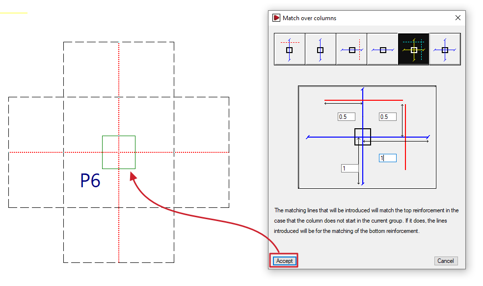
- Match over columns
Generates alignment lines or rectangles by entering dimensions from the column centreline to align the negative reinforcement on columns, either transversely, longitudinally or both. The alignment line is shown in blue in the icons in this window, and the length on either side of the line is shown in red. This allows the reinforcement of abaci to be standardised. If the column originates from the current group (for example, if the column is supported on a floor slab or sits on a foundation slab), instead of entering alignment lines for the upper reinforcement, the lines entered will align the lower reinforcement. - Redesign slabs
If the job has been analysed, this option reinforces the slab, taking into account the presence of reinforcement levelling bars and rectangles. - View all
Displays all the alignment lines and rectangles entered on the floor plan, regardless of the assembly type selected in the "Options" section of this window. - Clear
Removes the balancing lines or rectangles that are not in contact with two-way slabs. To delete them, you must select the reinforcement type in "Options" where the balancing lines or rectangles were entered.
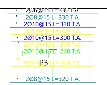
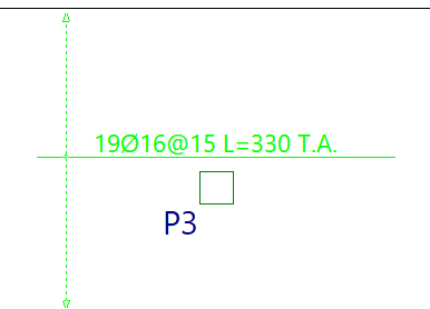
Reinforcement matching consists of determining an envelope of reinforcement, which is roughly equivalent to selecting the largest cross-sectional area and length of reinforcement from all the ribs or reinforcement bars intersected by each matching line.
Matching lines or rectangles will be drawn in red if they are for upper beams and in blue if they are for lower beams, and they remain in place even if the structure is redesigned.
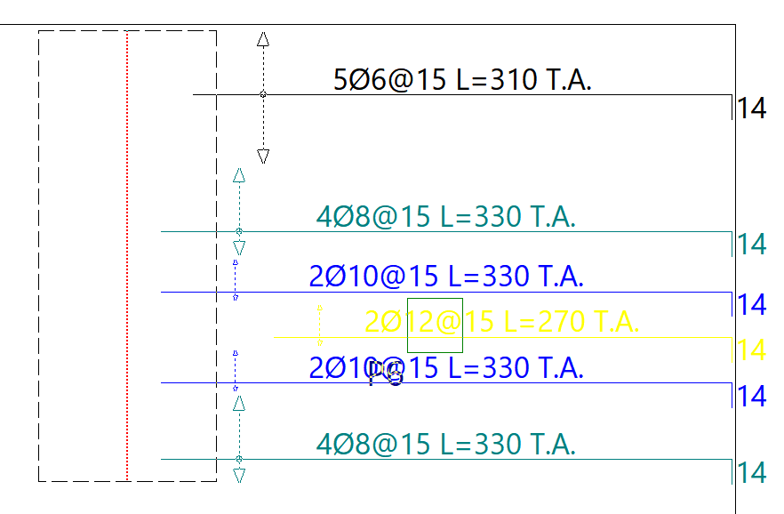
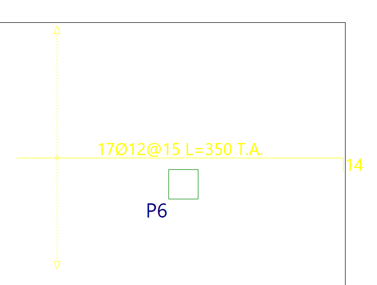
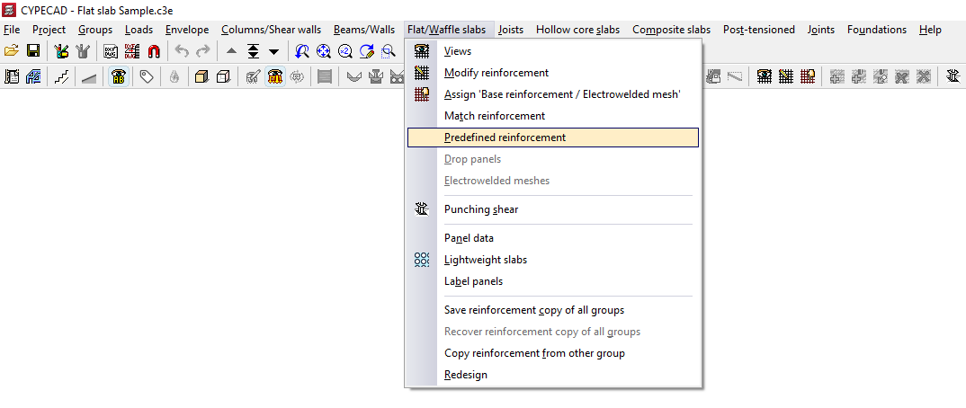
Inserting default reinforcement in slabs and waffle slabs
The "Predefined reinforcement" option, available in the "Panels" menu on the "Beam input" tab and also in the "Slabs/Waffle slabs" menu on the "Results" tab, allows the user to freely enter reinforcement in slabs and grid structures in any direction.
The predefined reinforcement, like the base reinforcement, is retained in subsequent redesigns, and its quantity is deducted from the required amount when analysing the reinforcement layout.
After clicking on this option, the "Predefined reinforcement" window opens, which contains the following options.
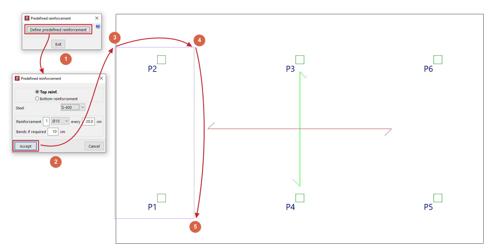
Enter predefined reinforcement
Use "Enter default reinforcement" to enter reinforcement for grid slabs and slabs in any direction.
After clicking on the option, in the window that appears, you must specify the position of the default reinforcement, whether it is an "Top reinforcement" or a "Bottom reinforcement", and select one of the available "Steels" (you can specify a different steel grade to the one selected for the main reinforcement of the panel). Define the "Reinforcement" by specifying the number of bars, their diameter and spacing, and indicate the length of the "Anchors if required".
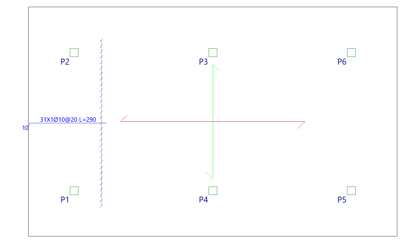
After clicking "Accept", the start and end points of the first beam are marked on the floor plan, and then a third point is selected to indicate the width of the distribution zone for the reinforced concrete package.
Delete default formatting (Upper/Lower)
The options "Delete default reinforcement (Top)" and/or "Delete default reinforcement (Bottom)" appear if default reinforcement has previously been entered on the top and/or bottom face of the slab, and allow it to be removed.
Regenerate bars
If default reinforcement has been entered and a change to the floor plan requires this reinforcement to be modified, using the "Regenerate bars" option will cause the program to redraw the bars, performing operations such as extending them or anchoring them at the ends, where possible.
| Note: |
|---|
| The program will deduct the default reinforcement from the analysed reinforcement, such that the average mechanical capacity of the default reinforcement entered (multiplied by the centre-to-centre distance in the case of a grid slab) will be subtracted from the analysed reinforcement. The average mechanical capacity of the default reinforcement is the result of dividing the total mechanical capacity of the entered default reinforcement by the width of the zone where that reinforcement has been entered. |
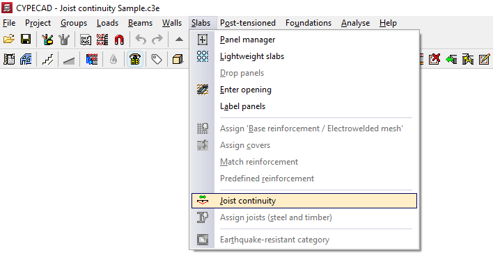
Joist continuity (steel and timber)
The "Joist continuity" option, within the "Sections" menu on the "Beam input" tab, allows you to set the continuity conditions for adjacent floor sections made of steel or timber joists.
In this way, the program will calculate the dimensions of each continuous joist in both sections as if it were a single piece.
When you click on the option, a dialogue box appears with the following options:
Add
This opens the "Type of span to calculate the deflection" dialogue box, which offers two options:
- Span with continuous overhang
This allows you to select a cantilever span and an adjacent interior span. In this way, the joists of the cantilever span are treated as continuous with the joists of the adjacent interior span. - Isolated span
This allows you to select two interior spans so that the continuity of the joists within them is treated as if they were a single isolated span.
After selecting one of these two options, left-click on two slabs made of steel or timber joists to establish continuity between them.
The beam between the selected sections will change colour to show the type of continuity applied.
In both cases, the program will treat the joist as a continuous beam and take this into account when calculating the deflection.
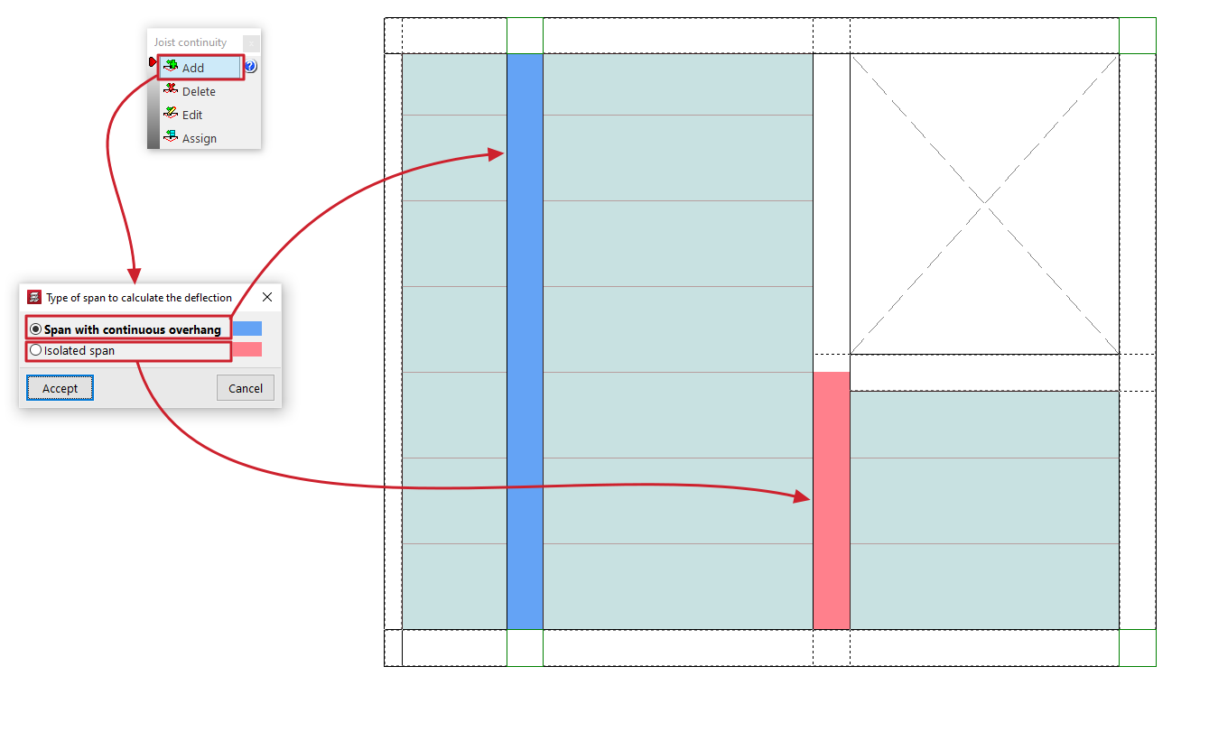
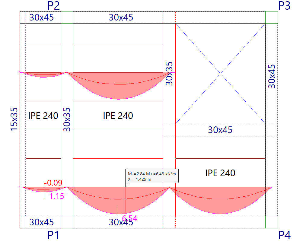
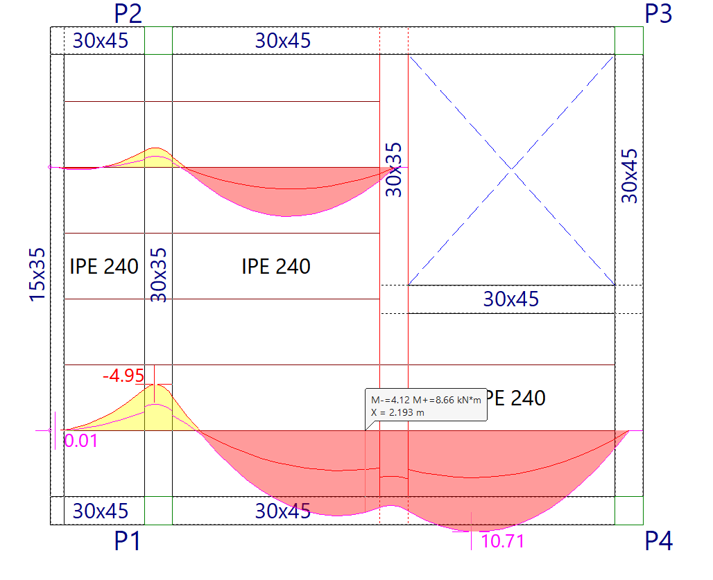
Delete
This allows you to select one of the beams located between two sections to which a joist continuity condition has been applied, thereby removing that condition.
Edit
This allows you to select one of the beams located between two spans to which a joist continuity condition has been applied, in order to modify it.
To do this, in the "Type of span to calculate the deflection" dialogue box that appears when you select the beam, choose one of the two conditions described: "Span with continuous overhang" or "Isolated span".
If you accept, the selected condition will be applied.
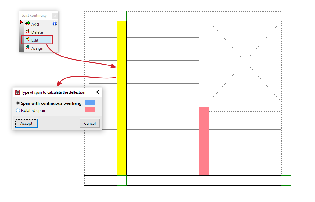
Assign
This allows you to apply the selected continuity condition to the beams located between two panels to which a joist continuity condition has already been applied (using the "Add" option).
To do this, in the "Type of span to calculate the deflection" dialogue box that appears when you click on this option, select one of the two conditions described: "Span with continuous overhang" or "Isolated span".
The "Assign" button allows you to select the beams to which the selected condition should be applied, either one by one or using a selection area, whilst "Assign to all" applies the selected condition to all beams with defined continuity conditions on the floor plan. The "Finish" option closes the dialogue box.
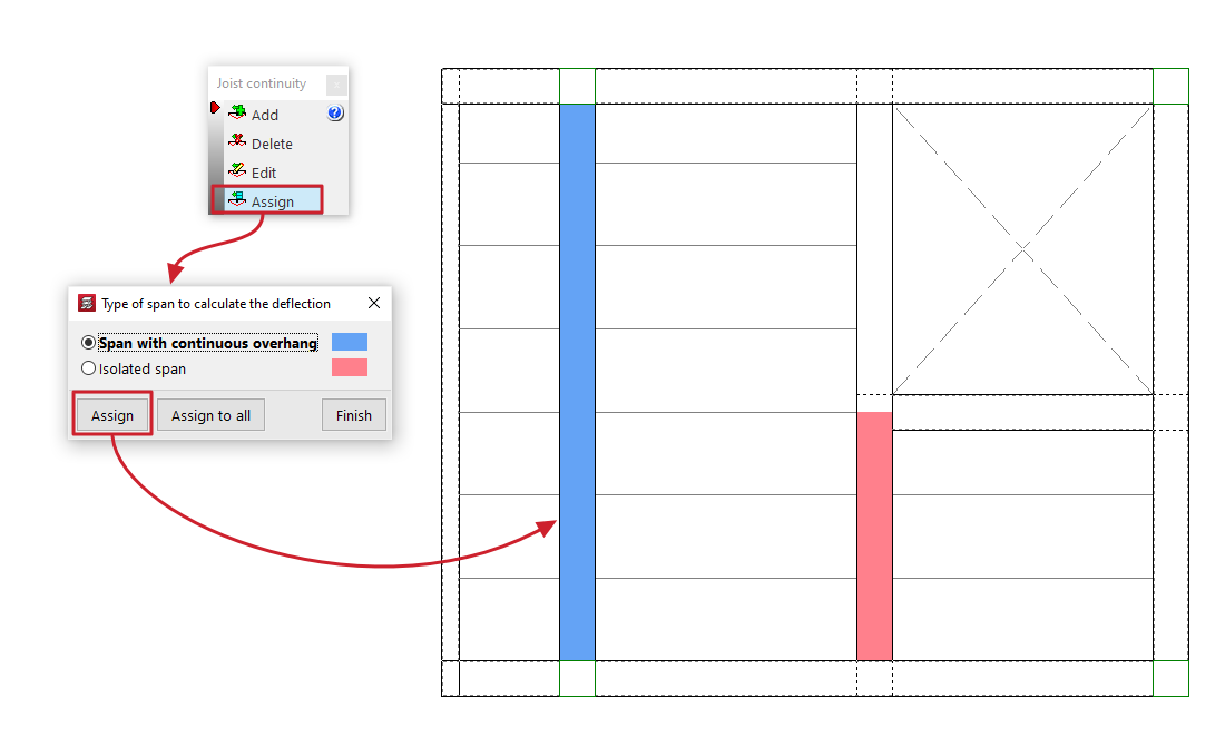
| Note: |
|---|
| If these continuity conditions are not applied, the result obtained is equivalent to designing each panel independently. In this case, steel and timber joists are treated as simply supported, whilst at the cantilevers, where necessary to maintain equilibrium, a fixed support at the end of these joists is automatically assumed, triggering the following error message: "Fixed or continuous ends in this type of joists are not designed". |
Assigning steel and timber joists
The "Assign joists (steel and timber)" option, within the "Panels" menu on the "Beam input" tab, allows you to change the type of joist used in floor slabs of this type by applying a bulk assignment of data to all selected joists.
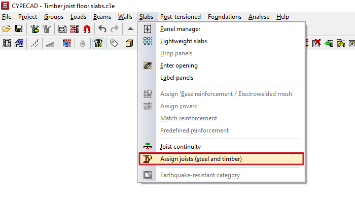
Next, click on "Assign" and select the joists on the floor plan to which you wish to assign this data. To do this, left-click on a point on the floor slab to select the starting joist, and then click on another point on the same slab to select the ending joist. The selected joists are highlighted in a different colour.
In the pop-up window, you can also use the "Select" option to copy the data for a selected joist on the floor plan, or "Cancel" to close the window.
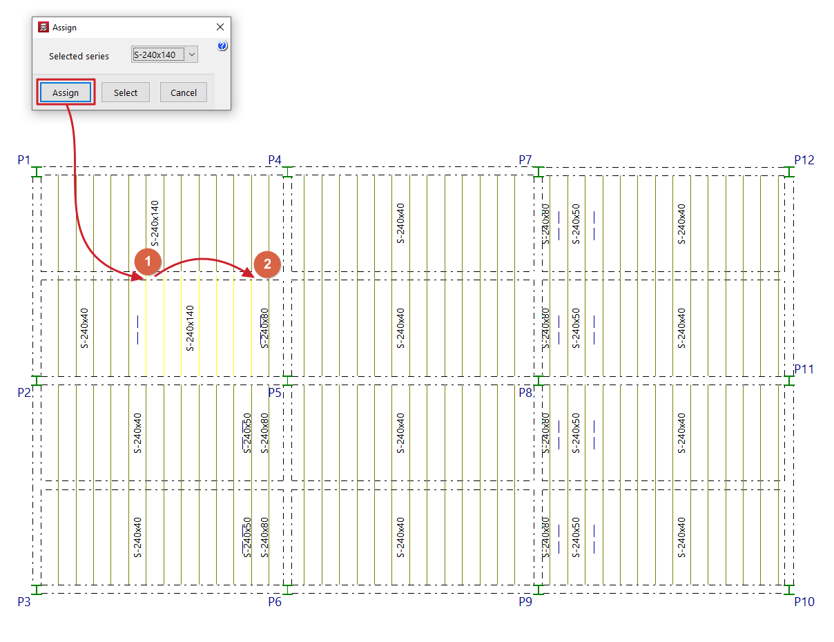
Earthquake-resistant category for floor slabs
For the seismic analysis of the structure, the program allows slabs of the following types of concrete floor structures to be classified as primary or secondary in terms of their role within the earthquake-resistant system:
- Unidirectional concrete joist floors (standard, precast reinforced, precast prestressed, or cast-in-situ, and floor systems).
- Lightweight slab floors (or hollow-core slab floors).
- Waffle slabs
- Flat slabs (reinforced and post-tensioned) and lightweight slabs.
To do this, use the "Earthquake-resistant category" option under the "Beam input" tab in the "Panels" menu.

In the dialogue box that appears, select one of the following options:
- Primary panels against seismic action
- Secondary panels against seismic action
By default, any panel added is assigned the "Primary panels against seismic action" category.
The "Assign" button allows you to select the panels to which the selected condition should be applied one by one, whilst "Assign to all" applies the selected condition to all panels on the floor. The "Finish" option closes the dialogue box.
The program uses a colour-coding system to indicate the status assigned to the various sections on the floor plan.

Concrete floor slabs classified as secondary are not considered part of the structural system for resisting seismic forces.
To this end, the stiffness of the secondary panels for seismic loadcases is reduced in the calculation based on the value defined in the "Inertia reduction factors" dialogue box (under the "Project > General options" menu). By default, this value is 0.01.

Table of contents
Complete your tour of CYPECAD by exploring the other available sections:
- Introduction
- Introduction and creating new jobs
- General data configuration
- Defining floors and groups of floors and inserting columns, shear walls and starts ("Column input" tab)
- Inserting beams, walls, floor slabs, foundation elements and special elements, and structural analysis (the "Beam Input" tab):
- Checking analysis results and editing elements (the "Results" tab):
- Options on the "Contour plots" tab
- Printing documents and exporting data
- More information:
- General features of CYPECAD