
Timber columns
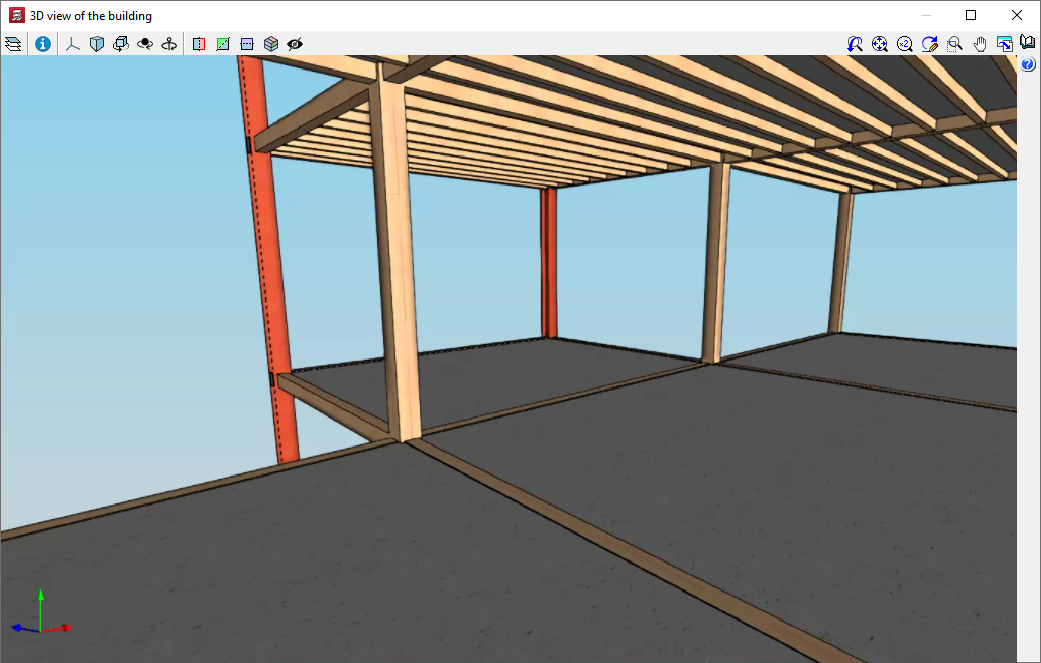
With the “Timber columns” module, CYPECAD can analyse and design rectangular and circular section timber columns.
Features of the “Timber columns” module
With the “Timber columns” module, CYPECAD can analyse and design rectangular and circular section timber columns.
Implemented codes
The implemented codes for designing and checking timber columns are the following:
- ANSI/AWC NDS – 2015 (ASD) (USA)
- CIRSOC 601 (Argentina)
- CTE-DB-SE-M (Spain)
- Eurocode 5
- Eurocode 5 France
- Eurocode 5 Belgium
- NBR 7190:1997 (Brazil)
Defining material, service class and duration of live loads
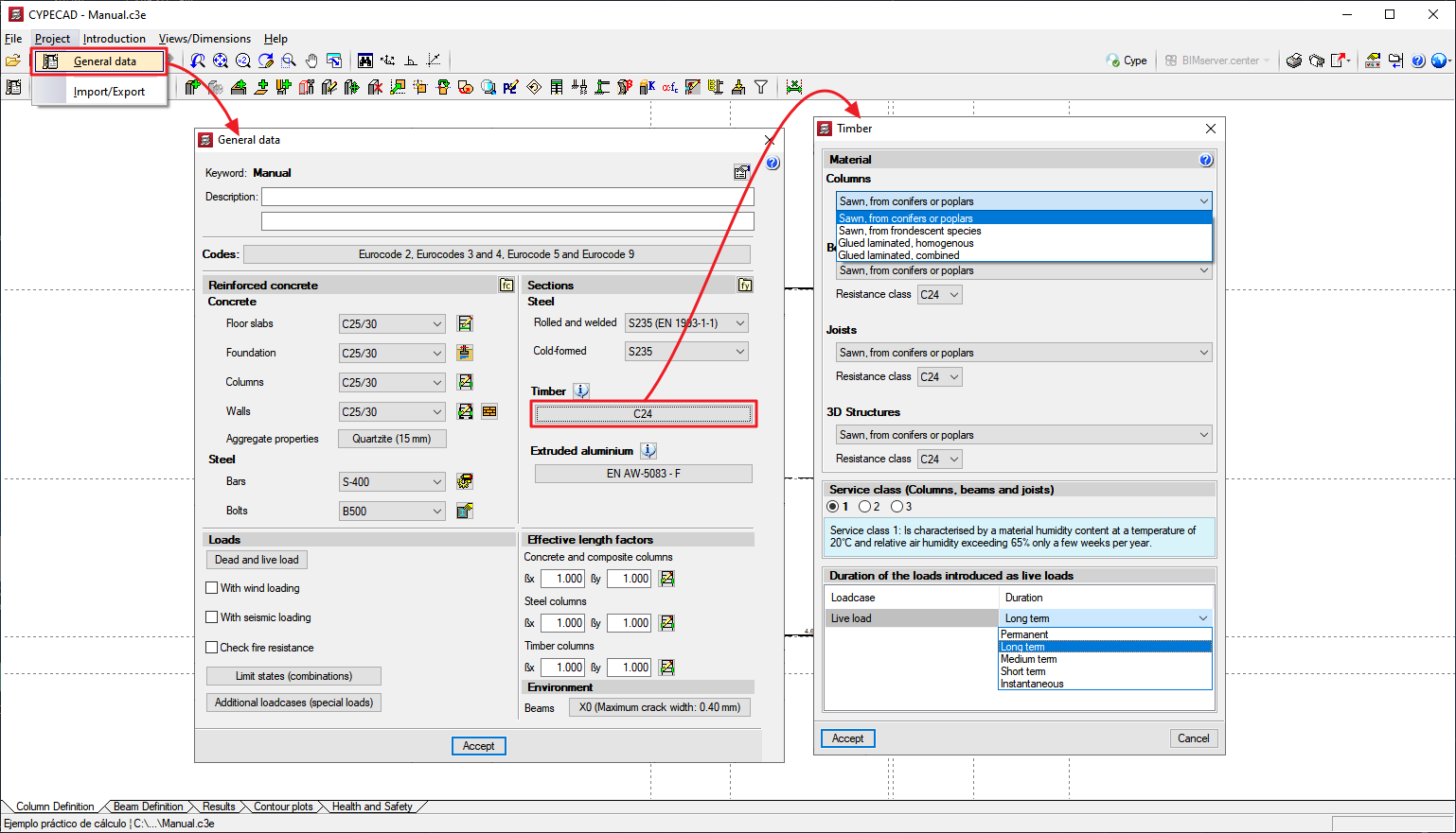
In the "Timber" section of the "General data" dialog box, the properties of the timber to be used are defined for each type of timber structural element that will be used in the project, such as columns. Users select the type of timber, its resistance class, the service class and the duration of the loads entered as live loads.
Entering timber columns
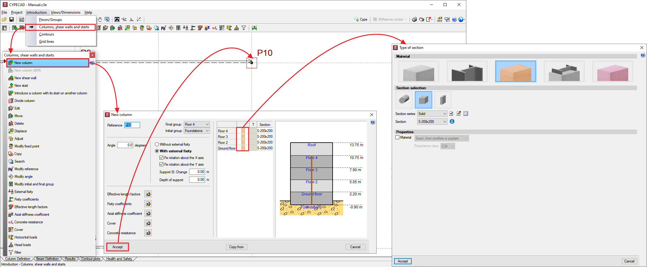
In the “Type of section” dialog box, users can select the “Timber” material and select the geometry of the section (circular, square or rectangular) and its dimensions.
The properties of the material (type of timber and resistance class) can also be defined for the column to be entered if they are different from those defined in “General data”.
Design
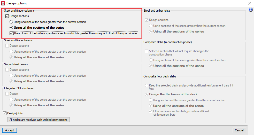
When carrying out the analysis, the "Design options" window will appear, where the program can carry out the design of the column sections, automatically searching for the best section that complies with all the checks. If the option is deactivated, the program will check the section defined by the user.
Results
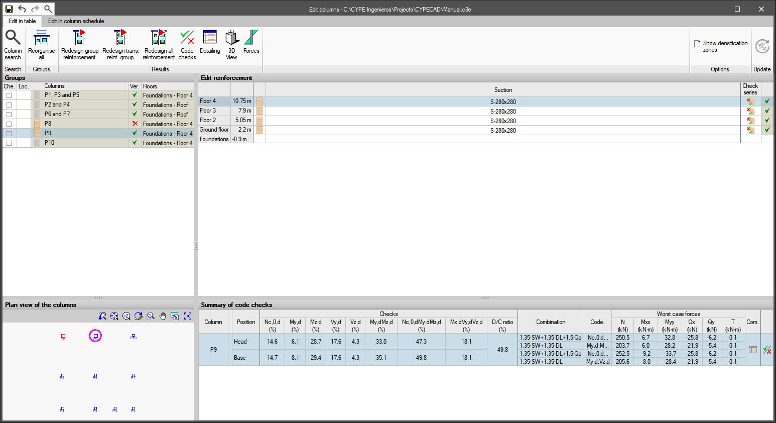
Once the project has been analysed, users can access the “Edit columns” dialog box where the summary of checks is shown (with a table view or a columns schedule), and the detailed list of checks can be accessed.

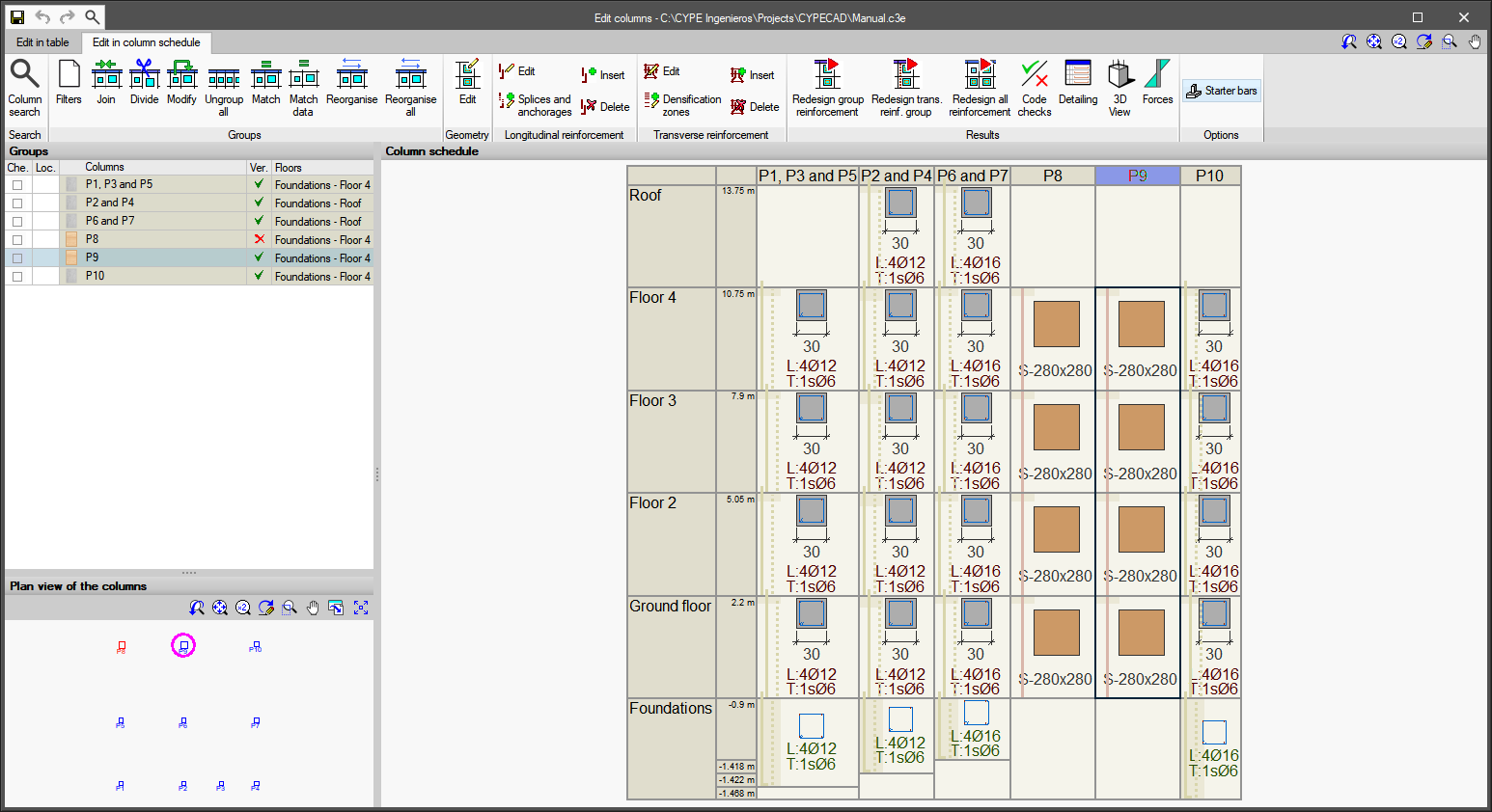
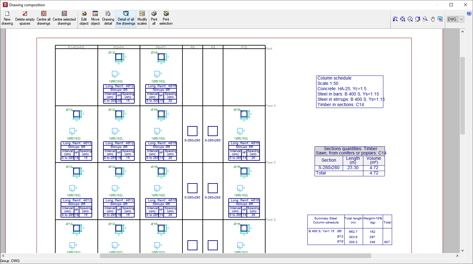
The “Column schedule” drawing includes every column in the project, regardless of the type of material selected for each of them.
Structural timber elements analysed in CYPECAD
In CYPECAD, users can define, analyse and design timber columns, timber beams and timber joist floor slabs with the modules listed below:
- Timber columns
With the “Timber columns” module, CYPECAD allows users to design rectangular and circular-section timber columns. - Timber sections
With the “Timber columns” module, CYPECAD analyses and designs generic timber beams and bars. This module also works in CYPE 3D.
Information at Timber sections. - Timber joist floor slabs
With the “Timber joist floor slab” module, CYPECAD analyses and designs timber joist one-way floor slabs.
Information at Timber joist floor slabs.
CYPECAD versions
CYPECAD is available in its unlimited version and also in two limited versions called LT30 and LT50, which contain the same tools and module acquisition possibilities, but have the following conditions:
CYPECAD LT50:
- Fifty columns.
- Four floor groups (Floor group: floors which are the same and consecutive).
- Total of five floors.
- Walls: one hundred linear metres. Feature available with the Building walls module.
CYPECAD LT30:
- Thirty columns.
- Four floor groups (Floor group: floors which are the same and consecutive).
- Total of five floors.
- Walls: one hundred linear metres. Feature available with the Building walls module.
Integrated 3D structures of CYPECAD (also LT50 and LT30) is not technically a module. To define these 3D structures in CYPECAD, users must also have the required permits to use CYPE 3D in their user license and, optionally, modules that are exclusive to CYPE 3D.
Other features
In order to access further features offered by the program, there are several modules that can be found on the "CYPECAD modules" webpage.