Steel types S280GD and S320GD have been implemented for Eurocode 3 (including the National Application Documents or general document adaptations for Bulgaria, France, Italy and Portugal) and EAE (Spain).


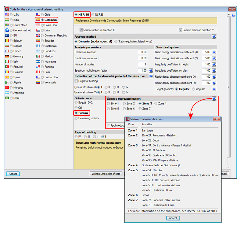
Improved code application. NSR-10 (Columbia). Microzonification of Pereira
Reglamento Colombiano de Construcción Sismo Resistente (2010).
This code was implemented in the 2011.c version for CYPECAD and Metal 3D. The specific calculation for the Seismic Microzonification of Bogotá D.C. was implemented in the 2011.k version, followed by the implementation of the Seismic Microzonification of Cali in the 2012.k version. Now, for the 2013.i version, the specific calculation for the Microzonification of Pereira has been implemented.
In the Code for the calculation of seismic loading dialogue box corresponding to the NSR-10 (Job > General data > activate With seismic action > select Colombia and NSR-10), users can select the seismic zones of Bogotá D.C., Cali or Pereira, or Remaining territory. When any of the specific zones are selected (Bogotá D.C., Cali or Pereira), any of their microzonifications can be selected. Upon selecting them, their corresponding seismic design spectrum definition will be defined.
Strut3D. Foundation pile check (Structures)
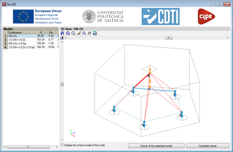
A new tool: Strut3D, has been incorporated in the 2013.e version of CYPECAD, Metal 3D and Foundation elements. Strut 3D checks foundation pile caps using a general calculation method in which the D regions of the reinforcement are analysed using a strut and tie model, in order to guarantee the structural requirements are met in accordance with the standards. The strut and tie model used has been previously validated by a linear finite element analysis.
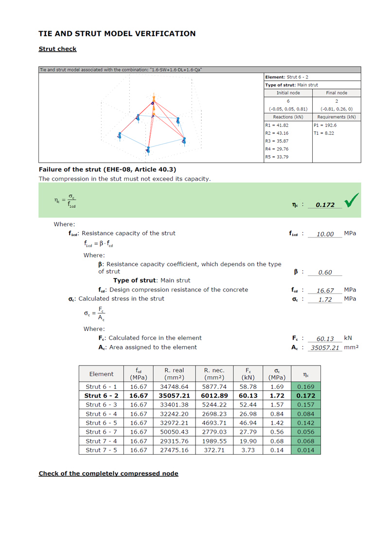
Additionally, Strut3D provides a graphical output of the results, allowing users to consult them on screen and in the detailed verification reports, which indicate whether or not they comply with the standards. The information provided is of great importance, as it is this information which will be used by the project designer when deciding on and justifying the design.
Strut3D is the result of a development project developed by CYPE with the collaboration of the 'Instituto de Ciencia y Tecnología del Hormigón' (ICITECH) of the 'Universidad Politécnica de Valencia' (UPV), financed by the 'Centro para el Desarrollo Tecnológico Industrial (CDTI) and co-financed by the European Regional Development Fund (ERDF).
Therefore, Strut3D is a breakthrough compared to other products currently in the market, because it verifies and justifies compliance with the design standards based on an optimised strut and tie model in a simple and intuitive manner for its users.
To access Strut3D in CYPECAD or Metal 3D, users must have a license providing access to version 2013.e or higher in either of these programs, and their Pile caps module. To access Strut3D in the Foundation elements program, users only require the program with version 2013.e or greater.
The first version of Strut3D currently only considers the Spanish EHE-08 concrete design code. More concrete design codes will be implemented in upcoming program updates.
More information on this CYPE program tool will be available shortly.
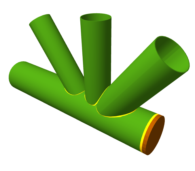
Unión en codo KT
Se trata de una unión de 3 piezas en disposición KT en el extremo del cordón de la celosía.
Al igual que sucede con el resto de uniones que dimensiona el módulo Uniones V, los diferentes tipos de secciones de perfiles tubulares resueltos (tubos circulares huecos, tubos rectangulares huecos, tubos cuadrados huecos y tubos formados por doble canal laminada en cajón soldadas con cordón continuo) pueden combinarse en el mismo nudo con las siguientes condiciones:
- Si los perfiles que forman los cordones de la celosía son tubos rectangulares huecos, tubos cuadrados huecos o doble canal en cajón; los perfiles de las diagonales y de las montantes pueden combinarse en el mismo nudo con cualquiera de las secciones tubulares implementadas (tubo circular hueco, tubo rectangular hueco, tubo cuadrado hueco o doble canal laminada en cajón soldadas con cordón continuo).
- Si los perfiles que forman los cordones de la celosía son tubos circulares huecos, los perfiles de las diagonales y de las montantes deben ser también tubos circulares huecos.