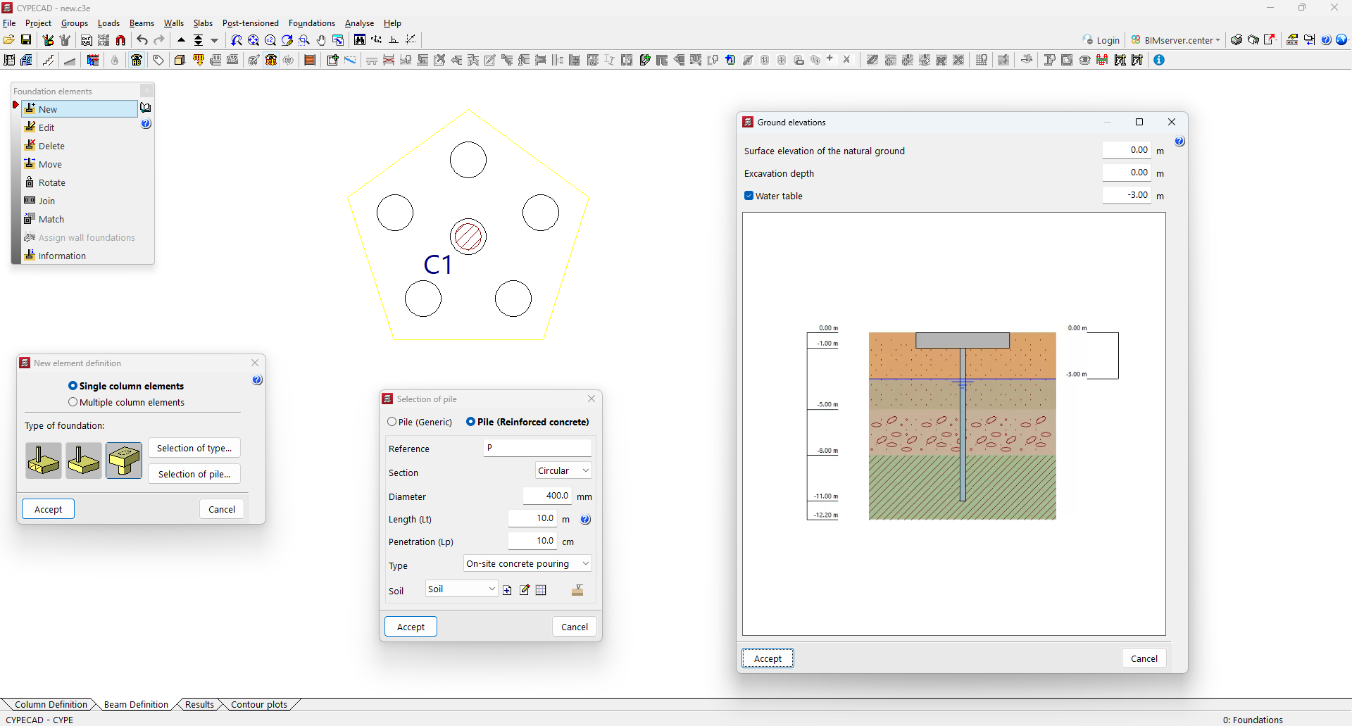
In version 2025.c, the calculation of the sinking load in deep foundations using reinforced concrete piles has been implemented for the "CYPECAD", "CYPE 3D" and "Foundation elements" programs. This implementation has been included in the new "Piles: Calculation of sinking load" module.
This module complements the design of deep foundations using pile caps, allowing users to verify the bearing capacity of the piles under different load conditions, considering the characteristics of the soil and the pile itself.
The program allows users to define several ground types, including cohesive soils, granular soils and rock formations. Each soil type can be configured with its specific geotechnical properties, allowing a customised analysis of the site characteristics. Furthermore, the defined soils can be reused, which optimises the modelling and design process. Piles can be either precast or cast-in-place, with square or circular cross-sections.
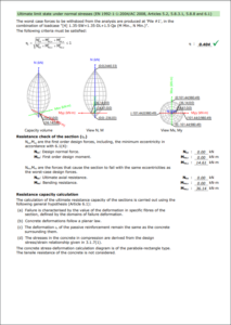
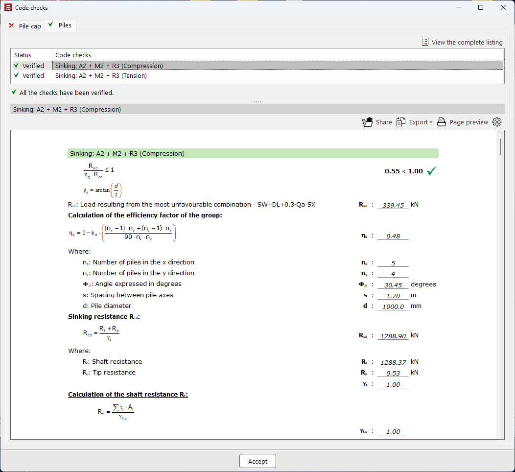
The resistance to sinking is obtained by considering the resistance per tip and shaft of the soil layer in contact with the pile. The calculation method used is based on analytical formulations based on the Mohr-Coulomb equation taken from the existing specific technical specifications. The verification has been implemented for the entire set of codes available in the CYPECAD, CYPE 3D and Foundation elements programs.
The "Check "option, accessible from the editing panel of the foundation elements, allows users to consult the calculations made to verify the safety of the piles.
To use this module, the following permissions must be included in the license, depending on the program where it is to be used:
- In CYPECAD
"CYPECAD", “Pile caps” and “Piles: Calculation of the sinking load”.
- In CYPE 3D
"CYPE 3D", “Pile caps” and “Piles: Calculation of the sinking load”.
- In Foundation elements
"Foundation elements” and “Piles: Calculation of the sinking load”.