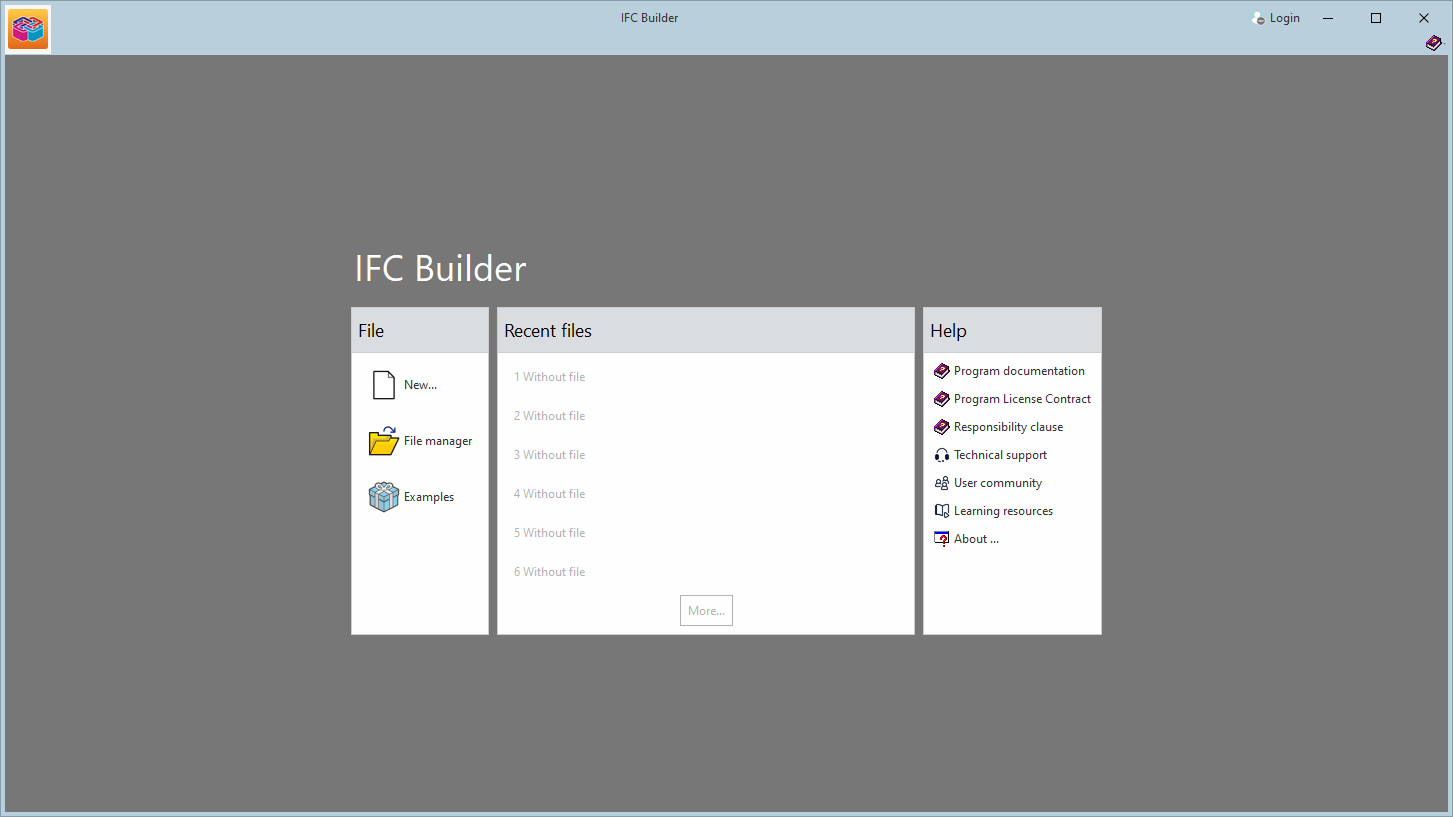
Several CYPE apps, including IFC Builder and CYPE Architecture, include a new feature for automatically converting DXF/DWG templates into 3D/BIM models, enabling the graphical information in the drawings to be interpreted to generate structural elements for the model. Among the elements that can be generated automatically are walls and partitions, as well as the building’s floor slabs. The license must include the "Automatic entry" module for this feature to work.

Checking permissions when sharing a contribution in the BIMserver.center project
As of version 2025.d, when clicking the "Share" option of the apps (before starting the generation of the contribution files), a check is made to ensure that the user is part of the BIMserver.center project team. If the user does not have the appropriate permissions, a warning message is displayed. This prevents the generation of unnecessary files when the user does not have editing rights.

BIMserver.center new features window
As of version 2025.d, the "Project selection" window in the apps connected to BIMserver.center incorporates a new notification system to inform users about the latest new features on the platform.
This space displays relevant messages about new features, enhancements and recommendations related to BIMserver.center. In addition, direct links to documents, tutorials and additional resources will be included to facilitate the adoption of these new features.

New furniture: stairlifts, platform lifts, grab rails, shower chairs and containers
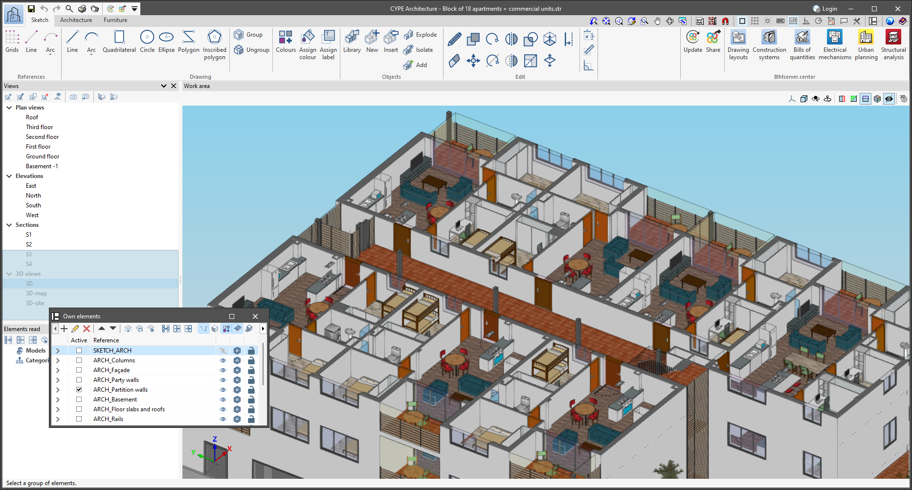
In version 2025.d, CYPE Architecture has new furniture elements grouped into two new sections: Accessibility and Waste.
- The "Accessibility" section contains the following: stair lifts, platform lifts, grab rails and shower chairs.
- The "Waste" section contains containers of different sizes, models and types (waste, organic, glass, paper and plastic).

Links to the CYPE website in the apps help menu
In version 2025.c, new options have been added to the "Help" menu of all CYPE apps, providing direct links to key resources on the CYPE website. These options make it easier to access to useful information and Technical Support, improving the overall experience of using the program.
The new options are the following:
- Technical support: This link provides information on the different ways of contacting the CYPE Technical Support team to clarify any queries, obtain customised assistance and solve any problem related to the apps.
- User community: This option provides access to the CYPE user community, where users can share experiences, ask questions and discuss solutions with other professionals using the same tools. This community encourages the exchange of knowledge and best practices, helping to make the most of the program's features.
- Learning resources: This link leads to a collection of learning resources, such as tutorials, manuals, videos and articles, designed to help you understand and use CYPE apps more efficiently. These materials are designed for all levels of experience, from beginners to advanced users, and are an excellent source of information to expand skills and technical knowledge.
These new additions make it easier to access information and provide the necessary support to improve the users' experience with the apps and to encourage professional development.
Transparent preview in dockable windows
In version 2025.c, the preview for moving dockable windows within the apps has been improved. Now, when dragging a dockable window, the preview of its docked position is displayed transparently, allowing a clearer view of the underlying work area.
This new feature makes it easy to find the optimal location for each dockable window without obstructing important elements or losing sight of relevant project information. It also provides a smoother and more modern visual experience, aligned with best practices in user interface design.
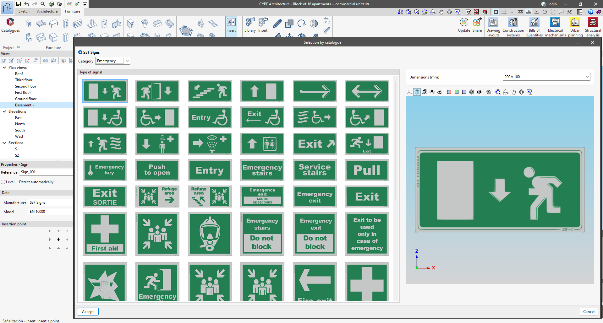
Downloading and entering signal catalogues
This new 2025.c version of CYPE Architecture includes the possibility of including signs in the BIM model.
This new feature can be found in the "Furniture" tab and is used to download manufacturers' catalogues and to enter signs for emergencies, fire safety, danger, banning, obligation and information, among others. The program includes catalogues for Spain, France, Portugal and the United Kingdom.
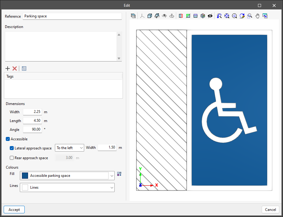
New option for including parking spaces
CYPE Architecture has a new option for including parking spaces in the job. This new feature can be found in the "Spaces" section of the "Architecture" tab.
- Creating types of parking space
Parking spaces, like the rest of the elements in the "Architecture" tab, are entered through types.
The types of parking spaces can be modified in terms of width, length and angle, and colours, as well as the accessibility conditions of the parking spaces.
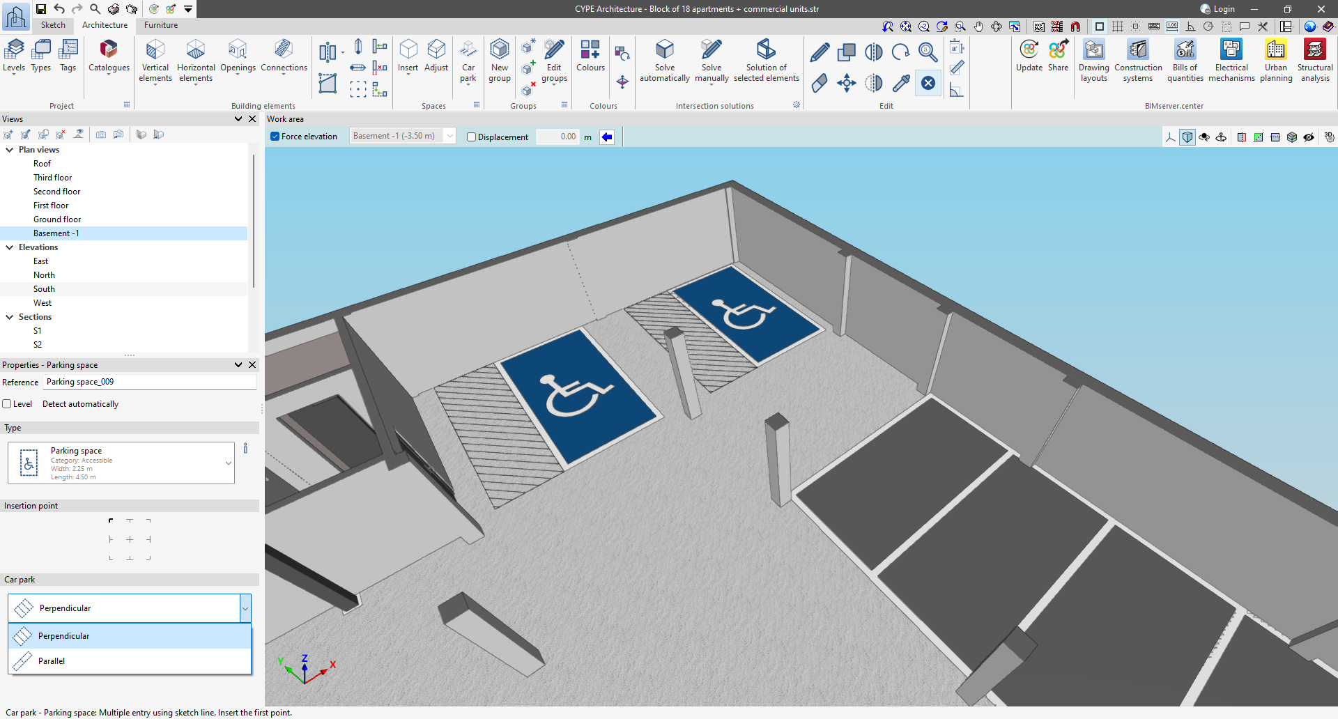
- Ways of entering parking spaces
There are two ways to enter parking spaces: individual and multiple.
Individual entry allows users to select the insertion point.
Multiple entry allows users to draw a line along which the parking spaces will be drawn. In multiple entry, there is a choice between placing parallel parking spaces and perpendicular parking spaces.
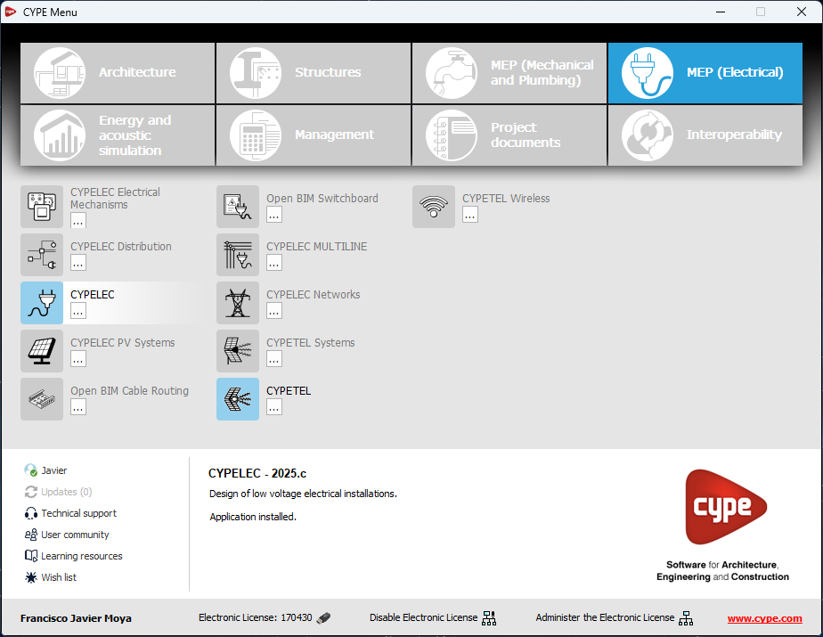
Changes to the apps available in CYPE Menu
The following modifications have been made to the apps available in the CYPE Menu:
New apps
- Now, in addition to the apps that are translated into the installation language of the CYPE Menu, there are also apps available in English.
Deleted apps
- CYPEPLUMBING Solar Systems. Integrated in CYPEPLUMBING.
- CYPETEL Schematics. Replaced by CYPETEL.
- CYPELEC Grounding IEC and CYPELEC Grounding IEEE. Integrated into CYPELEC and CYPELEC Distribution.