Now, from the BIMserver.center project information window (displayed by clicking on the project name visible in the top right bar of the application), the owner's public profile page can be accessed on the BIMserver.center platform via the link inserted in the text representing the owner's name.


New groups and applications. Installing and uninstalling
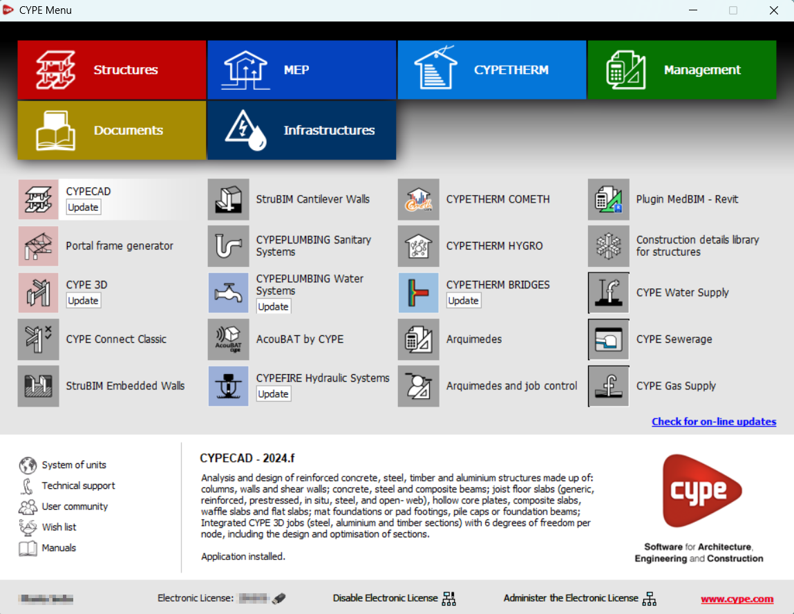
In version 2025.a, CYPE Menu (which can now be downloaded exclusively from the BIMserver.center platform) has new program groups.
- Architecture
- Structures
- MEP (Mechanical and Plumbing)
- MEP (Electrical)
- Energy and acoustic simulations
- Project management
- Project documents
- Interoperability
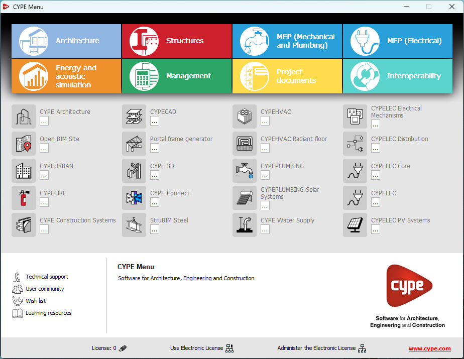
Most of the CYPE applications are sorted into these groups. In previous versions, most of these applications could only be downloaded as single applications from the BIMserver.center platform.
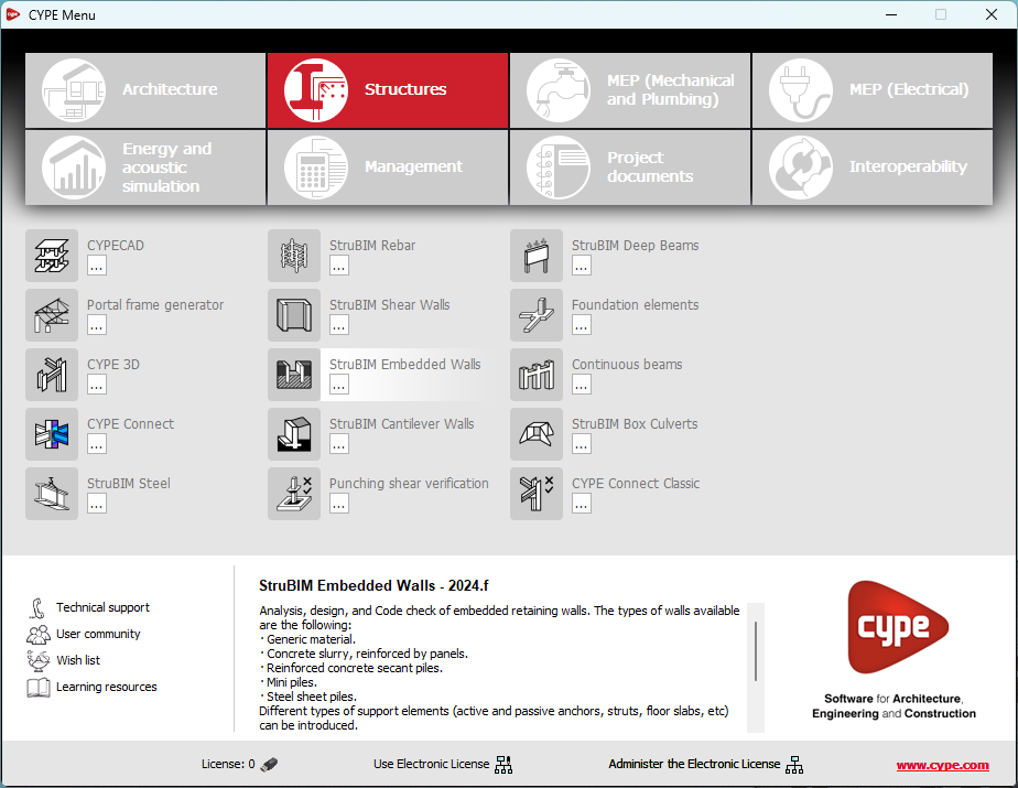
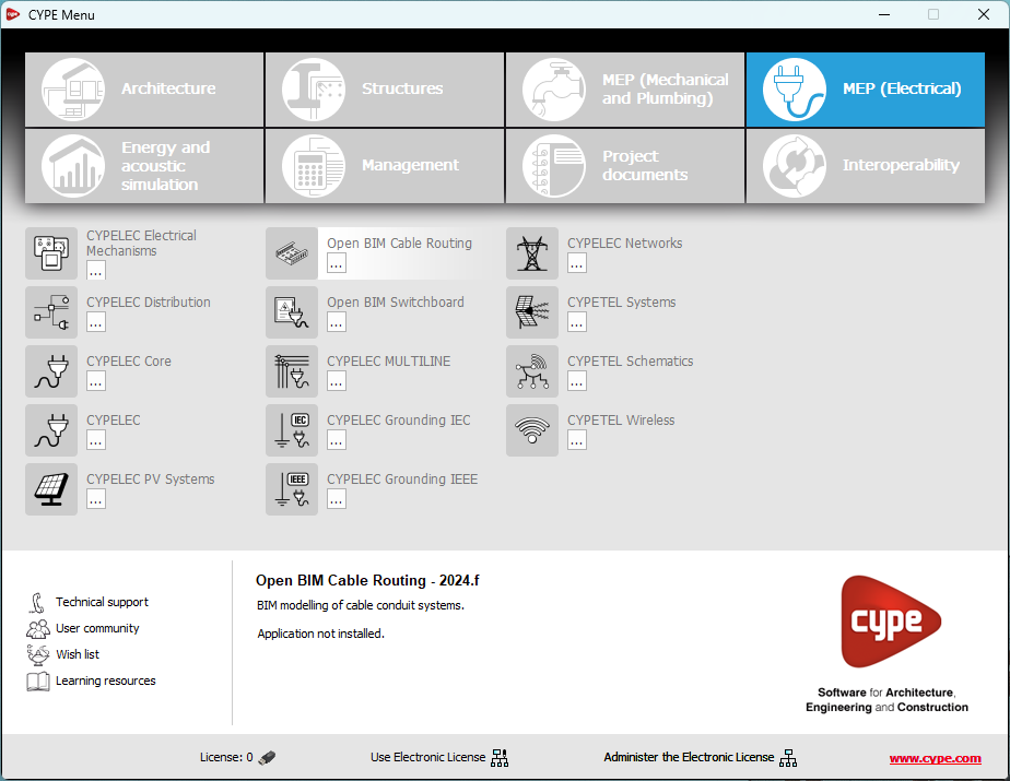
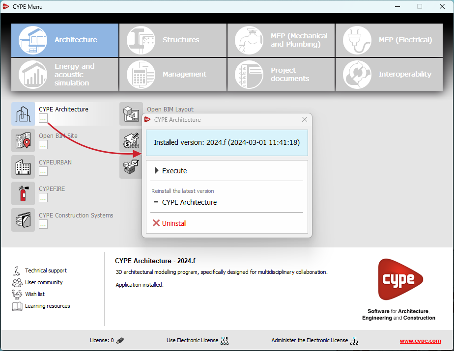
By downloading and installing CYPE Menu, users will only have the CYPE programs menu installed, but none of the applications included in it will be downloaded or installed. Initially, each of the icons representing the CYPE Menu applications appears in a box with a grey background. When clicking on any of them for the first time (or on the button under the application's name), a contextual menu will appear allowing users to download and install the latest version of that application or an earlier version if available. Earlier versions (from 2024 onwards) will be available for those programs that include paid modules. Normally, free applications will only allow the latest version of these programs to be installed. Any installed version of any application can be uninstalled.
When an application has been installed, by clicking on the button under its name, the context menu that appears includes the "Uninstall" option.
More information on this program menu can be found in the FAQ "How to download and install programs from CYPE’s general menu".
The CYPE Menu download of versions before 2025 (with the applications included) is still available in the download area of the CYPE website.
CYPE Menu. Exclusive download from the BIMserver.center platform
As of version 2025.a, the CYPE program menu can only be downloaded from the BIMserver.center platform.
The CYPE Menu application was already available from version 2024.b on the BIMserver.center platform. Now, in version 2025.a, the advantages of CYPE Menu compared to previous versions, which were downloaded from the download area of the CYPE website, are as follows:
- As of version 2024.b
- Once CYPE Menu has been installed, the applications it contains will be installed from this new menu when they are opened for the first time.
- Once CYPE Menu has been installed, the applications it contains will be installed from this new menu when they are opened for the first time.
- As of version 2024.f
- CYPE Menu allows users to manage the updates of the applications it contains.
- CYPE Menu allows users to manage the updates of the applications it contains.
- As of version 2025.a
- New program groups and many CYPE applications that could only be downloaded directly from BIMserver.center are included.
- The version of each application to be installed can be selected (from version 2024 onwards).
- Previously installed applications can be uninstalled.
Further information on the new features can be found in the following new features of CYPE Menu version 2025.a.
In the download area of the CYPE website, the download of the program menu for versions prior to 2025.a (in 64-bit and 32-bit) will still be available. In this download area, there is also a link to the BIMserver.center platform "Store" for downloading the 2025.a version of "CYPE Menu".
As a result of these changes, the 32-bit version of the CYPE Menu is no longer available in version 2025.a. As of 18 February 2019 (version 2019.f), the CYPE programs have been running on 64-bit systems. Since then, only the classic CYPE menu could be installed on 32-bit systems. All other applications (downloadable from the BIMserver.center platform) only worked on 64-bit systems. We believe that 32-bit programming is no longer feasible to take advantage of the superior performance of 64-bit processors and operating systems. Users who still want to use certain 32-bit CYPE programs (those available in the "CYPE Menu" prior to version 2025.a) must install a version prior to 2025.a from the download area of the CYPE website, but will not be able to upgrade their programs to later versions. Please refer to our FAQ question "Which version should I download, 64-bit or 32-bit?" for more information on the 32-bit and 64-bit versions.
Updating the CYPE Menu applications
As of version 2024.f, the CYPE Menu tool (available on the BIMserver.centre platform Store) allows users to manage the updates of the applications it includes.
When accessing the CYPE Menu, the program checks whether there is a newer version of the installed applications and, if so, the "Update" option appears next to them.
The update process will download the application and, once completed, will start the installation.
Shortcuts for all applications
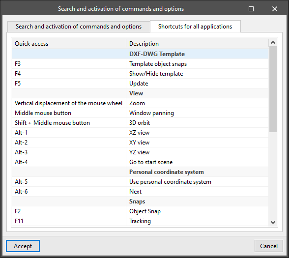
CYPE apps have keyboard shortcuts common to all programs. In versions before 2024.e, each program displayed the keyboard shortcuts for each app via the "Search and activation of commands and options" in the top left-hand corner of the programs.
As of version 2024.e, the "Shortcuts for all applications" tab has been implemented in the dialogue box displayed when selecting this option and it shows all the keyboard shortcuts common to CYPE apps.
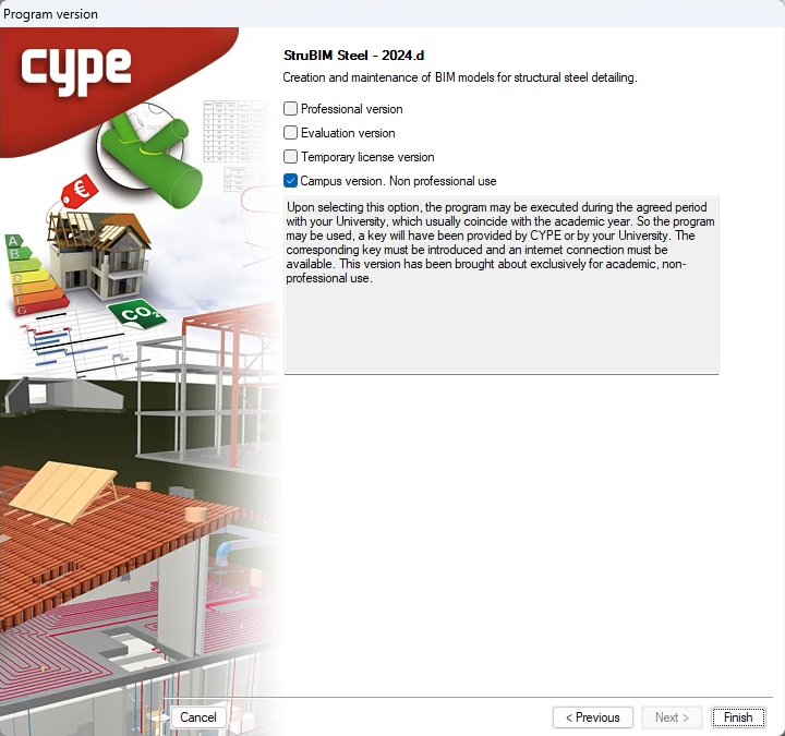
Installation modes (professional, campus, evaluation, temporary license)
All CYPE programs can be installed in their different versions (Professional Version, Evaluation Version, Campus Version, Temporary License). In previous versions, users could only choose the type of version to be installed from the classic CYPE menu.
As of version 2024.a, the selection of version types has been implemented in all CYPE programs on the BIMserver.center platform.
As of version 2024.d, this selection can be made during the installation of all CYPE programs, regardless of where they are downloaded.
Links to the BIMserver.center platform
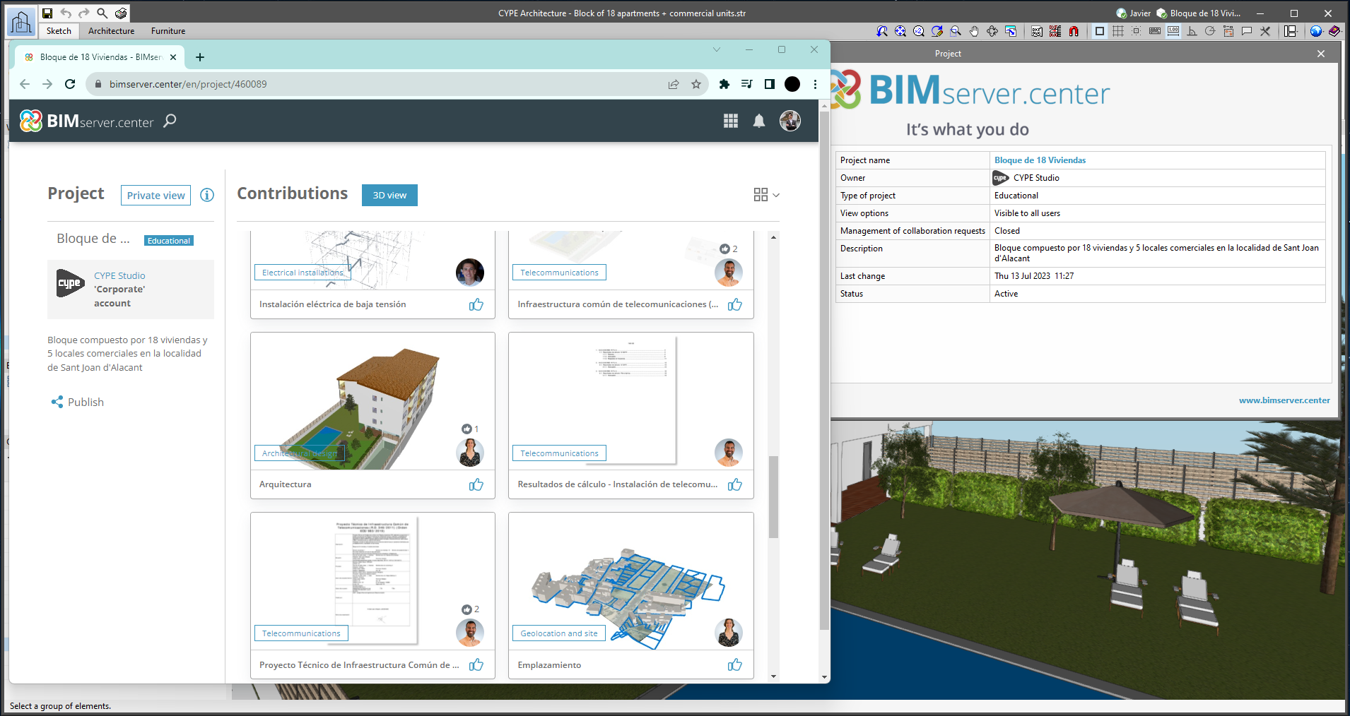
From the BIMserver.center project information window (displayed by clicking on the project name shown in the project information bar - upper right part of the application window) you can access the project page of the BIMserver.center platform via a link that has been inserted in the text indicating the project name.
Likewise, from the information window about the project contributions ("Contributions" option in the project information window), users can access the page of each contribution in the BIMserver.center platform. These links are inserted in the texts indicating the name of each contribution.
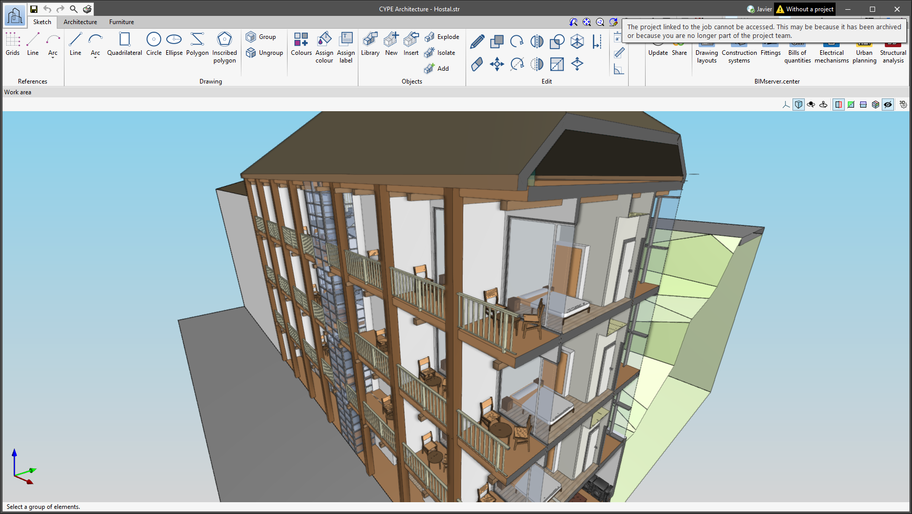
Notifications on the project status
The status information bar of the BIMserver.center project is located at the top right of the window of the programs included in the Open BIM workflow. This bar has been available in the applications since version 2022.e and shows a warning icon when there is a problem with the connection to the project, as well as other things. Now, in version 2024.b, users can obtain more information about the warning by hovering the mouse cursor over the icon.
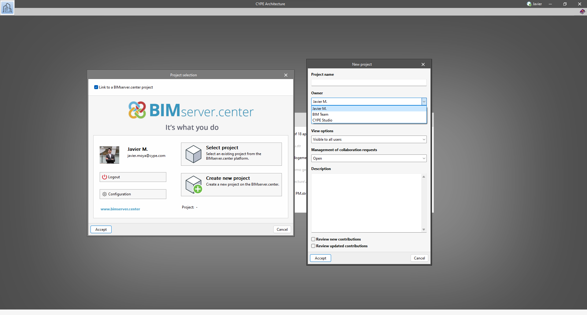
Creating BIMserver.center Corporate projects
As of version 2024.b, users can create projects associated with a "BIMserver.center Corporate" account from all CYPE applications included in the Open BIM workflow. To do this, the "Owner" field has been added to the window for creating a new project. This is a drop-down menu that includes, as one of the available options, the logged-in BIMserver.center user name along with the "BIMserver.center Corporate" accounts to which it has access. When selecting the user name as the owner, the project will be associated with this personal account, as was the case in previous versions. On the other hand, if a BIMserver.center Corporate account is selected, the project will be associated with that account.
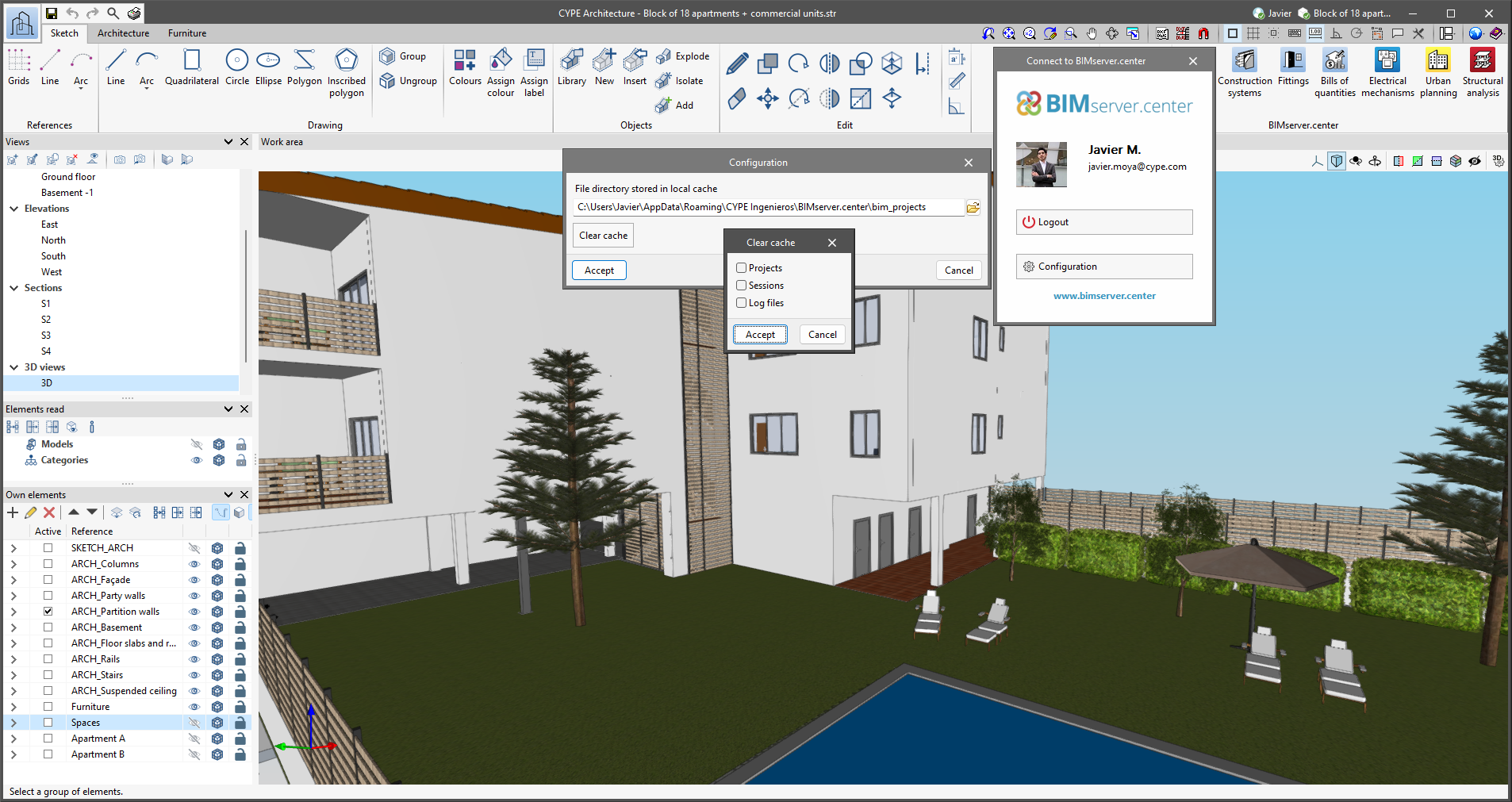
Clear cache
The "Clear cache" button has been added to the CYPE applications included in the Open BIM workflow in the "Configuration" dialogue box that opens with the following sequence of commands: Select any of the options in the "BIMserver.center" tool group > "Configuration" option in the dialogue box that appears. When clicking on "Clear cache", the following options are displayed:
- Projects
Deletes projects, contributions and documents downloaded from the platform that are in the "File directory stored in local cache". - Sessions
Deletes the data of any active sessions. This action will require applications to be re-authorised to access BIMserver.center. - Log files
Deletes transaction logging from applications with BIMserver.center.