New features

2023.a Version

31 May 2022
Index

New features common to several programs

Applications with a 3D environment

Managing the visibility and object snaps of external elements

A new tool has been implemented in the user interface that is common in Open BIM applications with a 3D working environment. Now, the management of the elements from the digital model of the building, which comes from the associated BIMserver.center project, is carried out from the "Elements read" menu located in the left sidebar of the application. 

The elements read are structured in the form of a tree based on two classification types: "Models" and "Categories". The organisation by "Models" allows users to inspect each contribution linked to the job and each associated 3D model within it. On the other hand, the "Categories" group the "Elements read" into families according to their features. Next to each tree component, three buttons are displayed to control the visibility, the display mode (solid, transparent or wire) and the object snap. It should be noted that the organisational settings applied to the organisation by "Models" prevail over those indicated by "Categories".

Applications can have default visibility and object snap settings when creating a new view. Furthermore, when entering new components with the tools in the program, the application itself can force the activation or deactivation of the visibility and object snaps of certain categories. When this happens, a yellow padlock will be displayed next to the set options. When users finish using the tool, the tree will return to its original state.

In previous versions, the management of the visibility of BIM project models was carried out in the configuration panel of a view. As a consequence of this improvement, editing is now managed from the "Elements read" menu in the left sidebar and has therefore been removed from the previous location. However, in the editing panel of a view users can indicate whether the view should have its own configuration for viewing these elements or whether it should use the general configuration of the job. For this purpose, the "Use a specific view configuration for the view" option has been added. When this option is active, the "View" text will appear in the "Elements read" menu.

In addition to the component tree of the external models, the "Elements read" menu includes a toolbar with a group of buttons that allow the following actions to be carried out:

  • Isolate selection
    Allows elements from the 3D model to be isolated. Users can select the elements of the 3D model that they wish to isolate and when right-clicking on them, the rest of the elements from the model will disappear.

  • Hide
    Allows the selected elements to be hidden. Users can select the elements from the 3D model that they wish to hide and by right-clicking on them, they will disappear.

  • Show all
    Shows all hidden elements.

  • Aspect
    Allows users to choose between normal drawing or monochrome drawing.

  • BIM information
    Displays a panel showing the attributes associated with the selected component.

In version 2023.a, the management of visibility and object snaps of external elements is available in the following CYPE Open BIM applications:

  • CYPE Architecture
  • CYPELEC Distribution
  • CYPELEC Electrical Mechanisms
  • CYPELEC PV Systems
  • CYPEPLUMBING Water Systems
  • CYPETHERM RE2020
  • CYPEURBAN
  • Open BIM Analytical Model
  • CYPE Construction Systems
  • Open BIM COVID-19
  • CYPE Lightning
  • Open BIM Sampling
  • Open BIM Site

Applications that have the "Print/Save the current view" tool

Exporting in FBX format

Version 2023.a of all CYPE programs that have the "Print/Save the current view" tool (usually all programs that display graphic information in a window) allows any generated 3D model to be exported in FBX format. This is one of the most common and accepted formats among rendering software (Twinmotion, Enscape, Sketchup+Vray, among others).

Exportation in FBX format is found in the dialogue box that opens when selecting the "Print/Save the Current View" button in any of the programs that include this tool. This feature allows users to export any element that is visible in the current window at that moment in FBX format (as well as elements that have been imported from other programs).

Implementing codes and improving their enforcement

Connections for steel structures

Implementation. NTC-DCEA 2020 (Mexico, CDMX)

"Normas Técnicas Complementarias para Diseño y Construcción de Estructuras de Acero (2020)" – Mexico, CDMX.

Chapter 10 "Connections" from NTC-DCEA 2020 for designing connections in steel structures has been implemented for the following programs:

  • CYPE 3D
  • CYPE Connect Classic

CYPE Architecture

Groups of elements

A new set of tools has been added to the top bar of the "Architecture" tab in the program. This is the "Groups" feature that allows architectural and furniture elements to be grouped together. Any modification made to a group will also have an effect on the equal groups, thus facilitating the modelling of the building and its subsequent corrections.

Groups are particularly useful in buildings with repetitive elements, such as types of dwellings or building premises.

The "Groups" feature has several tools:

  • New group
    Allows users to select the architectural and furniture elements to be included in a group and to give the group a name.
  • Copy group
    Creates a copy of a group, generating an equal group. Any modification generated in the group or its copies will be reflected in the rest of the equal groups.
  • Move group, Rotate group, Delete group and Edit group
    These tools allow all elements in the group to be edited at the same time.
  • Explode group
    Ungroups all elements in the group and deletes the group. The elements remain in the job, but no longer belong to a group.
  • Make unique group
    Creates a new group from an existing group, but this new group will not be linked to the original group nor to those that are equal.
  • Add elements to a group
    This feature can be used for adding an element to a given group. If an element is added, this action will also be carried out in the equal groups.
  • Unlink elements from a group
    This feature can be used for unlinking an element from a given group. If an element is unlinked, this action will also be carried out in the equal groups.

Space table reports

The program generates space table reports that can be displayed on screen by selecting the "Reports" tool in the program's top toolbar. The reports can be included in the technical specifications and are exported to the project.

Improved export of structural elements

The export of columns and basement walls has been improved:

  • The export of columns includes the insertion point
    This property is read and imported by CYPECAD from the architectural model generated by CYPE Architecture. CYPECAD uses it to define the fixed point of the column.
  • Basement walls are exported as load-bearing walls
    This property is read and imported by CYPECAD from the architectural model generated by CYPE Architecture.

Improved curtain wall properties

The curtain wall element has a new property: Indoor/Outdoor. This property is useful in the thermal analysis of buildings that include these elements.

More information on this new feature can be found in the CYPETHERM EPlus version 2023.a new feature "Curtain walls".

Improved program interface

  • Drop-down lists in the "Architecture" tab
    Some features in the "Architecture" tab (Levels, Groups, Stairs, Ramps, Elevators/Lifts) have been compressed into a button that displays a list of the different features in that section when selected.
  • Improved element selection in the "Furniture" tab
    The furniture style has been unified. Furniture is now chosen via an icon instead of a reference, making it easier to choose furniture.
  • Displaying information texts
    This option is fixed at the top right of the view, making it easier to read the properties of the elements.

Improved wall entry

Walls can be snapped at either end and not only at their directrix plane. The program detects when two walls come into contact with each other and, in that case, it also makes their directrix planes come into contact with each other. This improves the automatic detection of spaces by ensuring that the spaces are closed.

New example job

A new example job for a multifamily residential has been included in the program. It is a block of 18 apartments and commercial units and has been created to exemplify the use of the tools of the "Groups" set that has been implemented in this version.

Open BIM Site

Map editing tools

As of version 2023.a, the following features from the "Edit" menu in the toolbar can be used on the maps in the model:

  • Edit
  • Copy
  • Delete
  • Move
  • Move a group of elements
  • Rotate a group of elements
  • Measure

In order to use object snaps in the maps, the "Snap" option has been added to the list of components of the site model in order to activate it for this type of element.

When using the editing tools on topographic surfaces associated with a map, the modification will also be applied to the texture generated by the map.

Open BIM Construction Systems

Exporting technical data from construction systems for thermal and acoustic analysis software

As of version 2023.a, "CYPE Construction Systems" can share the complete technical data of the construction solutions entered in the job in the BIMserver.center project. This information can be displayed in the 3D view of the applications as well as in the web viewer of the BIMserver.center platform.

The applications can use the technical data to complete the parameters of the models. The CYPE Open BIM applications currently capable of reading and incorporating the construction systems from "CYPE Construction Systems" in their analysis model are as follows:

  • Thermal simulation
    • CYPETHERM HE Plus
    • CYPETHERM EPlus
    • CYPETHERM LOADS
    • CYPETHERM RT2012
    • CYPETHERM RT2012 CNOA
    • CYPETHERM SCE-HAB
    • CYPETHERM SCE-CS Plus
    • CYPETHERM C.E.
    • CYPETHERM COMETH
    • CYPETHERM RTExistant
    • CYPETHERM RE2020

  • Acoustic simulation
    • CYPESOUND
    • CYPESOUND CTE

Acoustic simulation tools can read the fields available within the "Sound insulation" tab of the technical data editing panel, while thermal simulation applications can read the fields available within the "Thermal insulation" tab. In order for the applications to be able to read the technical data, they must be running version 2023.a or higher.

Open BIM - Revit Plugin / Bills of quantities of Revit models (Arquimedes)

IFC Uploader

Sets of properties and quantities from the IFC file in the glTF viewer file

As of version 2023.a, "IFC Uploader" can incorporate the sets of properties ("IfcPropertySet") and quantities ("IfcQuantitySet") defined in an IFC into the glTF viewer file. This information associated with each component of the model can be consulted from the 3D view of Open BIM applications and in the web viewer of the BIMserver.center platform.

Open BIM Analytical Model

Summary of the analytical model generation

As of version 2023.a, "Open BIM Analytical Model" displays a panel with a summary of the elements added to the project after completing the automatic generation process of the analytical model. The added components can be consulted from the "BIM Model" option in the program's toolbar.

Changes in the management of visibility and object snaps of elements in the physical model

Due to the new management of visibility and object snaps of external elements system, the "Snap options" panel in Open BIM Analytical Model has been modified in order to remove the components of the physical model and thus avoid duplication. The "Template" tab now has only two elements: "Spaces" and "Openings".

Additionally, the "Show/Hide template" option in the toolbar has been removed as this action can now be performed from the "Elements read" panel in the left sidebar of the application.

New warning and error system

A new project review process has been implemented to detect possible inconsistencies in the analytical model and, thus, make it easier for the user to solve them. To do so, the following options have been added to the "Errors" group in the application toolbar:

  • Checking errors
    Runs the error checking in the project. This check is also performed at the end of the automatic analytical model generation process.

  • Checks
    Displays the configuration panel where the checks to be carried out in the project are established. A distinction is made between errors and warnings occurring on components of the physical model and those relating to the analytical model. For the physical model, certain elements can be excluded from the analysis. Some checks are not active by default as they require longer analysis times; these are displayed in the panel with a warning symbol.

  • Show/Hide incidents
    If this option is activated, elements where an issue has occurred will be highlighted. If it is an error, a red circle will appear next to the component; if it is a warning, a yellow triangle will appear. When the mouse pointer is positioned over the symbol, the message describing the error will be displayed. If the incident occurs on an analytical surface, it will change colour (red when it is an error and yellow when it is a warning) to help identify the affected object.

Improved entry of surface points

When entering an analytical surface in previous versions of Open BIM Analytical Model, all of its points needed to be coplanar. Now, the first three points inserted into the work area determine the surface plane, while the rest are projected onto said plane. This makes it much easier to enter new surfaces by means of the template snap from the physical model.

Tool for generating analytical surfaces from the 3D contour of a space in the physical model

The "Generate analytical surfaces based on a space of the physical model" option has been added to the "Elements" group in the Open BIM Analytical Model toolbar. This feature allows users to obtain the surfaces outlining a space from the physical model and creates the equivalent analytical surfaces. The space will also be added to the analytical model and all generated surfaces will be assigned to that space.

Tool for assigning the properties of a surface of the physical model to an analytical surface

The "Assign the properties of a surface of the physical model to an analytical surface" option has been added to the "Elements" group in the Open BIM Analytical Model toolbar. When selecting an analytical surface with this feature, a list of all available construction elements is displayed. Users can choose one of them and its properties will be assigned to the surface. If the application detects that a component of the physical model may correspond to the analytical surface, it will be marked by default.

This tool is also available from the editing panel of a surface. In this case, a blue arrow icon has been added next to the surface reference. Clicking on it will display the list of available construction elements.

Tool for generating an opening in an analytical surface from an opening in a physical model

The "Generate an opening in an analytical surface based on an opening of the physical model" option has been added to the "Elements" group of the Open BIM Analytical Model toolbar. When using this feature, an opening from the physical model and a surface from the analytical model can be selected. Based on the geometry of the opening, the program will create an opening in the selected surface and a new surface with the "element in opening" attribute at the position of the opening.

Other improvements and corrections

Version 2023.a of Open BIM Analytical Model includes other minor improvements and corrections of the program for certain cases:

  • Inserting an opening in an analytical surface
    When inserting an opening on an analytical surface, the surface containing the opening was assigned as the element in the opening. This has been fixed in version 2023.a.

  • Modifying the points of an opening
    A problem that occurred when modifying the points of an opening has been fixed. The program did not allow the surface containing the opening to be redrawn. Although this was not an analysis error, it generated a strange effect in the 3D model.

  • Generating analytical spaces
    An error that could appear when generating the analytical spaces during the automatic generation process of the analytical model has been fixed.

  • Adjacencies of the analytical surfaces
    An error that could occur when determining the adjacencies of analytical surfaces during the automatic generation process of the analytical model has been fixed.

  • Entering an opening with the “Orthogonality” tool
    Orthogonality can now be used when entering an opening into a surface of the analytical model.

CYPECAD

Exporting the rebars of shear walls and stairs to the BIM model

The rebars of shear walls and stairs can now be exported to the BIM model.

In the current version of the program, CYPECAD exports the reinforcement of the following types of elements:

  • Concrete walls
  • Columns
  • Shear walls
  • Beam frames
  • Stairs
  • Foundation elements (footings, pile caps, strap beams and tie beams)
  • Slabs (waffle slabs, joist floor slabs, hollow core plate floor slabs, composite slabs and flat slabs) 
  • Corbels

This reinforcement can be viewed in the StruBIM Rebar program along with the reinforcement exported from StruBIM Shear Walls.

They can also be viewed in CYPECAD in the "Results" tab (Groups menu > 3D view with details).

Beam intersections references

The “Beam intersections references” option has been added to the “Groups” menu of the “Beam definition” and “Results” tabs. These references can now be generated automatically according to the order of the frames.

For jobs created from version 2023.a onwards, this will be the default option. For jobs that have already been created, the order in which they were generated is maintained, but the "Beam intersections references" option can be used to change the order.

Improved design and checking of beams and columns with the Spanish structural code "Código estructural" and the Eurocodes

Two options ("Slope angle of the compression struts" and "Tolerances in spacing checks") and several improvements have been implemented in order to optimise the check and design of beams and columns. These options and improvements are available for the following codes:

  • Eurocode 2 (EU)
  • Eurocode 2 (Spain)
  • Eurocode 2 (Portugal)
  • Eurocode 2 (France)
  • Eurocode 2 (Romania)
  • Eurocode 2 (Malaysia)
  • Eurocode 2 (Singapore)
  • Código Estructural (Spain)

These new options can be accessed via the “General data” panel:

  • General data > Bars > By position > Options for columns, shear walls, walls and corbels > Design / Code checks.
  • General data > Bars > By position > Beam options > Design / Code checks.

The new options and improvements are detailed below:

  • Slope angle of the compression struts
    Allows the angle between the compressed concrete struts and the longitudinal axis to be defined, which is to be considered in the shear resistance analysis. The program allows users to assign one general slope angle for the struts in all the columns of the structure, and another one for all the beams of the structure.
  • Values can also be assigned individually to columns and beams using the following options:
  • For columns
    Column definition tab > Columns, shear walls and starts menu > Slope angle of the compression struts.
  • For beams
    Beam definition tab > Beams menu > Other options > Assign the slope angle of the compression struts.
  • Tolerances in spacing checks
    The “Tolerances in spacing checks” option has been added for beams and columns. This option allows the value of the tolerance that is permitted when carrying out the minimum and maximum spacing checks between reinforcement bars to be defined. If the difference in absolute value between the value required by the code and the calculated value is less than the tolerance considered, the check is compliant.
  • Analysis of the spacing between transverse reinforcement crossties
    The analysis of the spacing between transverse reinforcement crossties has been improved.
  • Analysis of the concrete area for circular composite columns with embedded sections
    The analysis of the concrete area for circular composite columns with embedded sections has been improved. The radius of the circular concrete section is taken as the minimum value between "the actual section radius" and "the maximum radius permitted by the code", which defines limits for the maximum thickness of the concrete cover in fully embedded sections.

Other improvements and corrections

CYPECAD version 2023.a includes other minor improvements and corrections of the program for certain cases:

  • Deleting jobs
    In “File management” (“File” menu), several jobs can be selected in order to delete them simultaneously.

  • Floor diagram in the "Import of BIM models"
    In the "Floor plans" section of the "Import of BIM models" wizard, a floor plan diagram has been added to visually check if the floor plan dimensions to be imported are as expected.

    In some cases, the diagram does not appear because the information exported to the IFC file by the program where the model has been designed has not been generated according to the IFC standard. The best solution for these cases would be for this information to be exported correctly but, if this is not possible, the "Zo" value of "Local reference system of the model" in "Geographical location and reference system" can be modified. At this stage of the import wizard, the necessary instructions are given to match the plant dimensions to the expected ones.

  • Import of BIM models - Columns
    The fixed point of columns in BIM projects designed with CYPE Architecture is imported.

  • Improved selection of reinforced and prestressed joist floor slab sheets
    As of version 2023.a, users can select a card containing a concrete with a lower "fcd" than the one selected in the job.

  • Updating a BIM project
    An error that occurred when updating a BIM project after adding a floor with beams to the project has been fixed.

  • Reorganising beam alignments
    The warning message that appears when using the "Reorganise" option in the "Beam alignments" dialogue box ("Beam definition" tab > "Beams" menu > "Beam alignments") if there are alignments with previously assigned references has been improved.

  • Inertia reduction factors
    The values of "Inertia reduction factors" have been modified when the selected seismic code is 'P100 - 1/2013 (Romania)'. Previously they were the default values; now they are the values indicated by this code.

  • Generic column reinforcement with asymmetrical transverse section
    The generation of generic column reinforcement with asymmetrical shapes has been improved. In some cases, this reinforcement was generated with interchanged axes.

  • Beam assembly reinforcement tables
    The editing of the beam assembly reinforcement tables has been improved in order to allow the same entry to be used in different width and/or depth ranges.

  • Sloped beams
    The entry of sloped beams has been improved. After selecting the first point the zoom setting is maintained. Previously it was changed in order to display a complete view of the floor plan.

  • Concrete column resistance
    Four decimal points are allowed in "Concrete resistance > Reduction coefficient to be applied to the concrete resistance".

  • Adjusting beams
    In the "Beams > Adjust" option, the template snap has been improved. Previously, in some cases, the desired line could not be selected from among all the lines in the template when they were in close proximity to the beam.

  • Improved drawing of walls arranged on top of other walls
    On rare occasions, the drawing of one wall on top of another in the initial group of floors of the wall was not carried out correctly.

  • Importing jobs from CYPE 3D
    The import of CYPE 3D works as integrated 3D Structures has been improved. As of version 2023.a, jobs with user-defined project situations can be imported.

CYPE 3D

Assigning critical buckling axial forces and critical lateral buckling moments

As of version 2023.a, CYPE 3D allows users to assign the values of critical buckling axial forces and critical lateral buckling moments for rolled and cold-formed steel elements as an alternative to the buckling and lateral buckling lengths.

This new feature provides a tool to consider values for the axial and critical moments of the element other than those calculated automatically by the program. The options (Bar menu > Buckling / Lateral buckling) are available for the following codes:

  • Eurocodes 3 and 4
  • Código Estructural (Spain)
  • EAE-2011 (Spain)
  • CTE DB SE-A (Spain)

CYPE Connect / StruBIM Steel

Analysing the rotational stiffness of connections

Version 2023.a of the "CYPE Connect" and "StruBIM Steel" programs includes the analysis of the rotational stiffness of the connections. With this analysis option, users can obtain as results the resistant moment, initial stiffness, secant stiffness and classification of the connection (rigid, semi-rigid or pinned) of the steel section.

To obtain the "Moment - Rotation" graph, the program carries out an iterative process by analysing the rotation in different load steps. The resistant moment is obtained when any element in the connection (plates, sections, welds or bolts) no longer complies, i.e. its demand capacity ratio is greater than 100%.

The "Analysis" tab includes the "Rotational stiffness" tool in the top toolbar. If the tool is selected, the rotational stiffness analysis is run.

Furthermore, the "Analysis" tool has been renamed. In previous versions, the "Analysis" button was used to run the stress and deformed shape analysis. This button will now be called "Stress / Deformed shape".

The results can be viewed on the right-hand side of the "Analysis" tab. The top drop-down menu allows users to choose the type of results to be displayed, "Stress/Deformed shape" or "Rotational stiffness". By selecting "Rotational stiffness" the program displays two tables and the "Moment - Rotation" graph.

The first table shows all the analysed bars with their secant stiffness and the connection classification in each plane. The second table shows the load cases analysed for the selected bar. Each load case will indicate the acting moment, the resistant moment, the secant stiffness and the initial stiffness.

The graph shows the curves for "Moment - Rotation", "Acting moment of the selected load case", "Resistant moment", "Ultimate stiffness for rigid connections (Sj,1)" and "Ultimate stiffness for pinned connections (Sj,2)".

As a result of implementing the rotational stiffness analysis, the following changes have been made to existing tools in the program:

  • Selecting bars and load cases
    Using the "Loads" button, the dialogue box is launched allowing users to select the bars from which the rotational stiffness of their connection is to be analysed. In the centre of this dialogue box, there are two tabs for defining the load tables, per load case. The "Rotational stiffness" tab requests a list of loads, the lengths of the elastic bar in the structural model (used to establish the limit stiffnesses of rigid or pinned connections) and the kb factor.
  • Generating from the BIM model
    By using the "Generate from BIM model" button, the dialogue box for applying filters and importing loads is launched. This version also includes options for importing loads for the rotational stiffness analysis. In addition to the loads, the elastic lengths of the bars in the structural model are also imported, these lengths are necessary in order to classify the connection correctly. Five options are provided for importing load cases depending on the forces:
    • Maximum moments, with simultaneous forces
      Imports load cases that have larger My or Mz moments, either positive or negative, as well as all other simultaneous forces.
    • Maximum moments, without the other forces
      For the maximum moment load cases, only the values of My and Mz are imported.
    • Maximum moments by plane, with simultaneous forces
      Imports load cases with maximum moments and their simultaneous forces per plane, i.e. creates load cases with forces per plane (XY and XZ).
    • All
      Imports all load cases.
    • None
      Does not import any load case.
  • Classifying the connection
    In order to classify the connection as rigid, semi-rigid or pinned, the limit stiffnesses for rigid and pinned connections are first established. Depending on the selected steel code, the initial stiffness or the sectional stiffness is compared with these limits.

IFC Builder

Exporting spaces in the glTF file

As of version 2023.a, IFC Builder exports job spaces to the 3D visualisation file in glTF format. Thanks to this improvement, spaces are now displayed in the 3D view of applications that read contributions generated with IFC Builder, as well as in the web viewer of the BIMserver.center platform.

The geometry of the spaces is contained in a separate glTF file from the one containing the construction elements.

CYPELEC PV Systems

Open BIM Lightning

CYPEPLUMBING Water Systems

Automatically generating localised pressure drops in pipe joints

In version 2023.a of CYPEPLUMBING Water System, the "Localised pressure drops in pipe joints" tool has been implemented. This tool allows users to automatically generate the pressure drops that occur throughout the pipe run caused by the following types of joints:

  • 45º elbows
  • 90º elbows
  • Tees
  • Diameter reducers

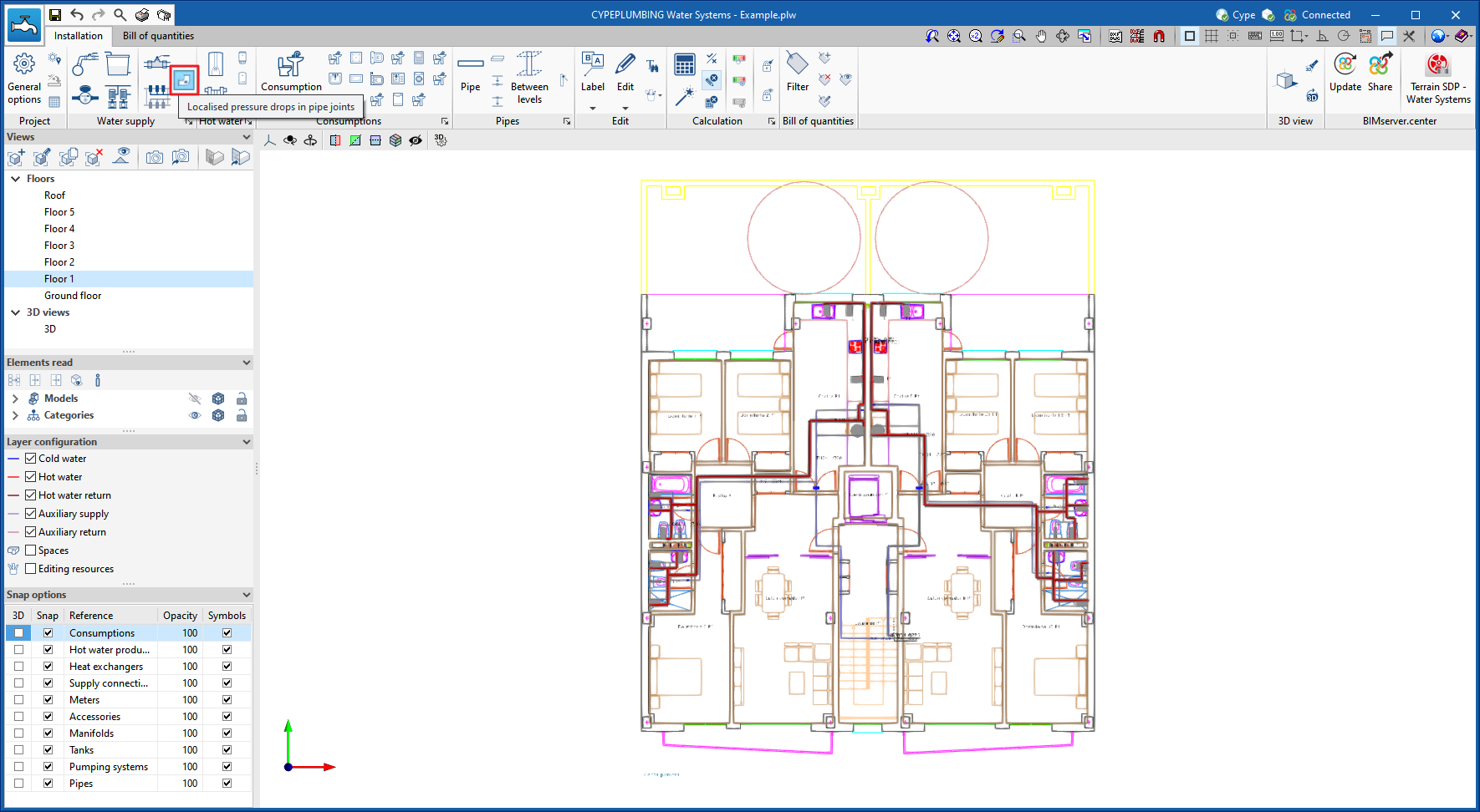
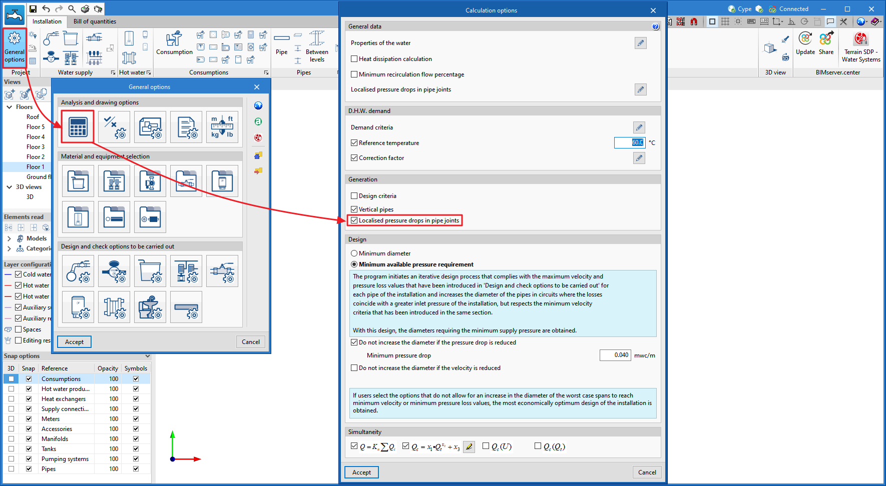
This tool can be activated in two ways:

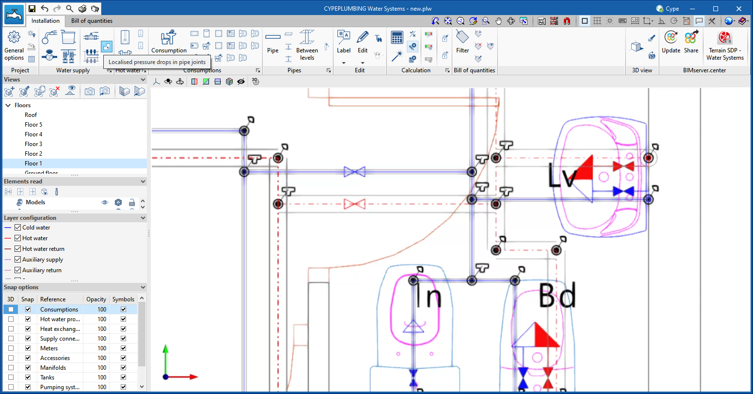
  • From the top toolbar when entering the system
    In this case, users can review the generated joints before the analysis.
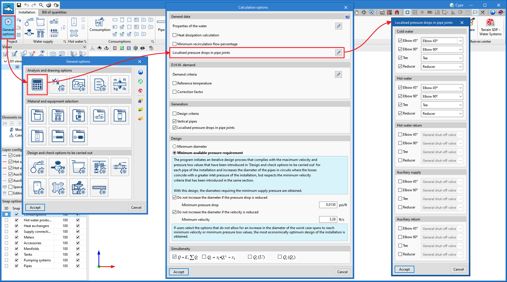
  • From the analysis options
    The joints and their pressure drops are generated when the system is analysed.

The analysis of these pressure drops is fully configurable and several analysis methodologies can be applied, taking into account the "diameter and equivalent length", "diameter and pressure drop ", or "diameter and kinetic coefficient" ratios.

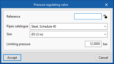
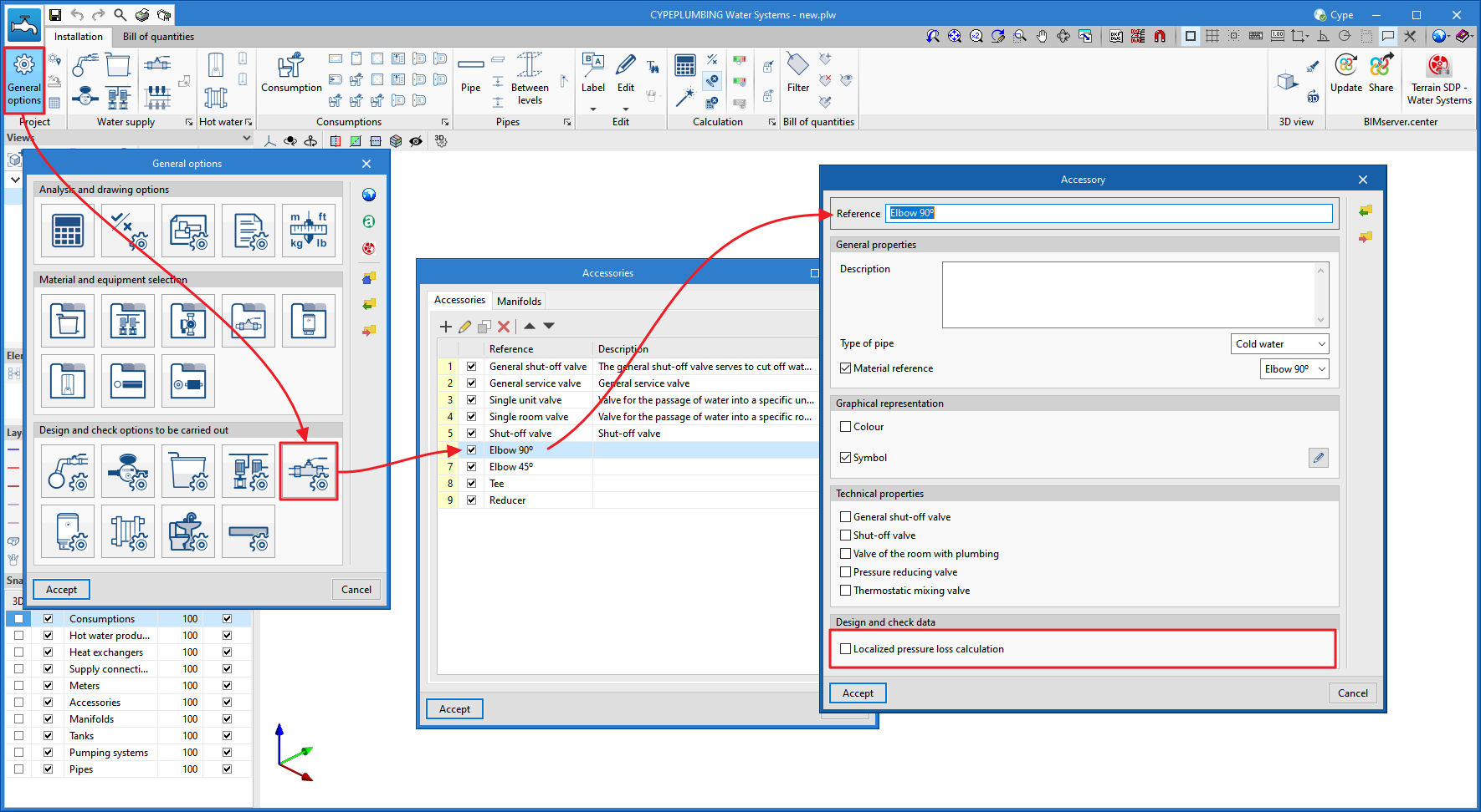
For this purpose, the "Accessories" option is added ("General options" > "Materials and equipment selection") where users can enter these factors, which may be code-based or directly consulted in the manufacturers' technical catalogues (normally in the latter case it is the kinetic coefficient of the type of joint).

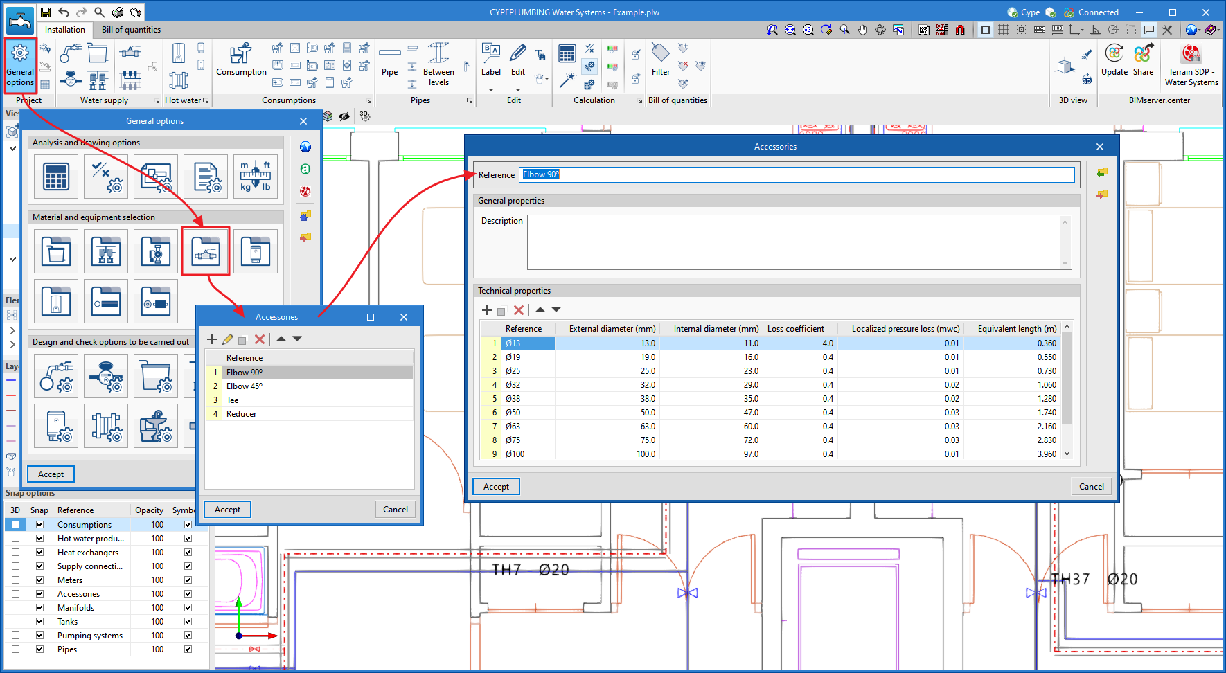
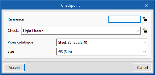
Then, the analysis criteria to be used for each type must be set.

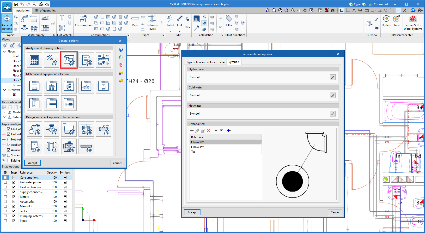
Users can set the symbols to be used.

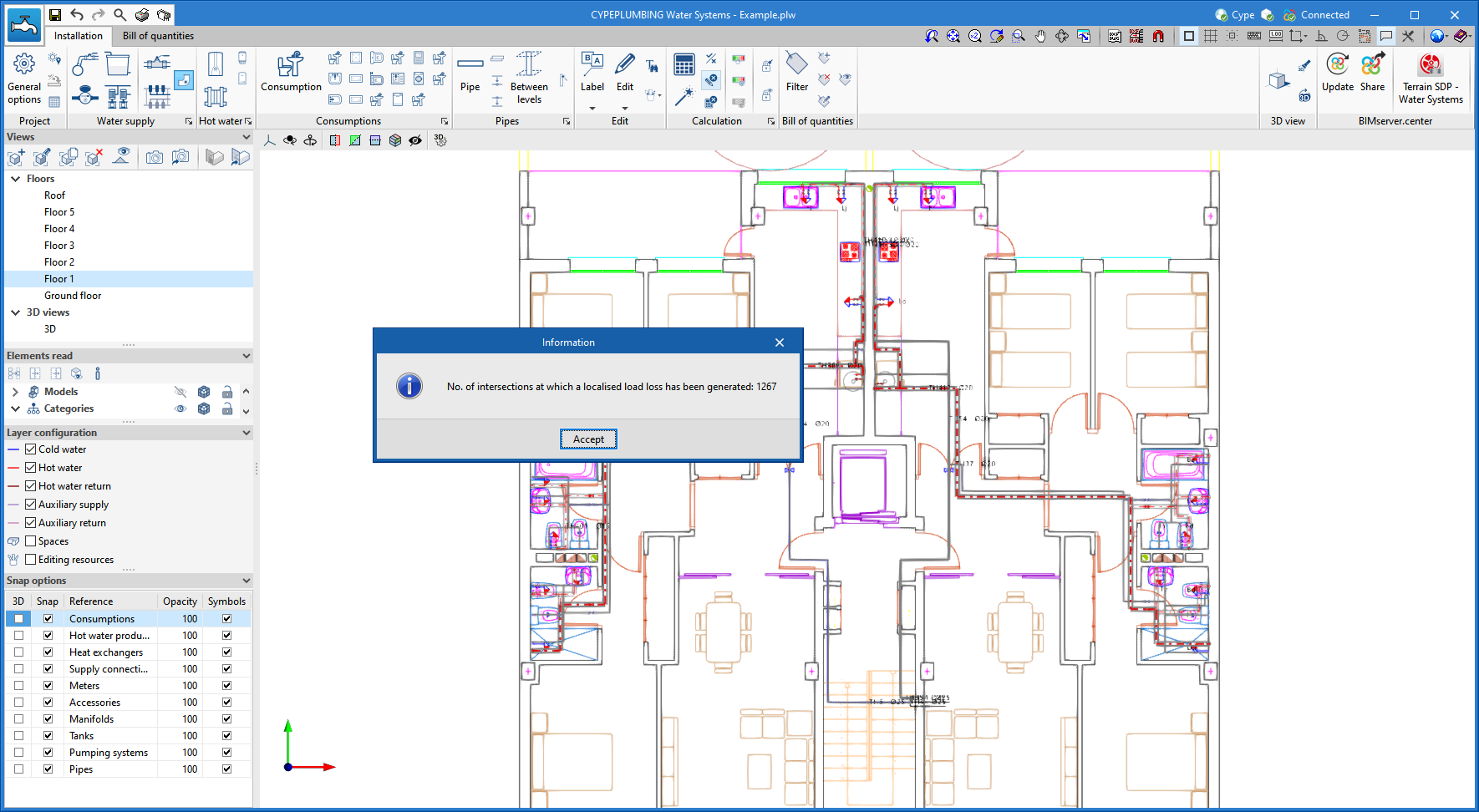
In its most basic mode, the "Localised pressure drops in pipe joints" tool can also be used to count only the number of joints according to the indicated types ("45° elbows", "90° elbows", "tees" and "reducers"). To do this, simply deactivate the calculation of the localised pressure drop.

Finally, the options that the program will assign to each type of joint must be activated.

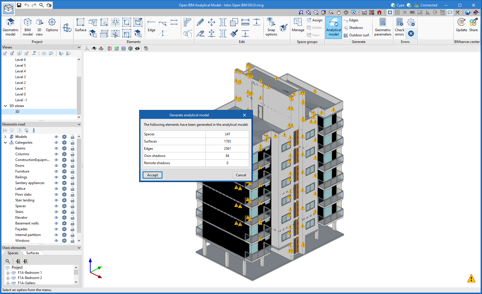
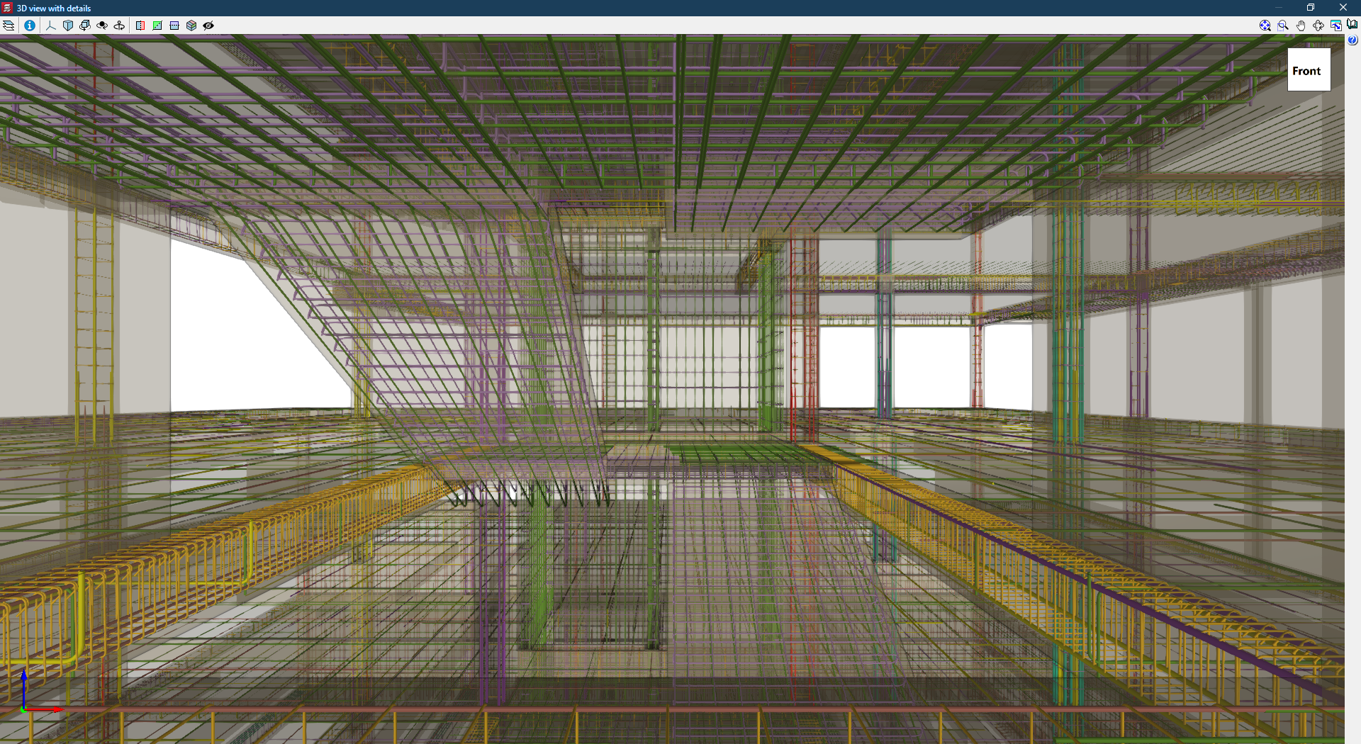
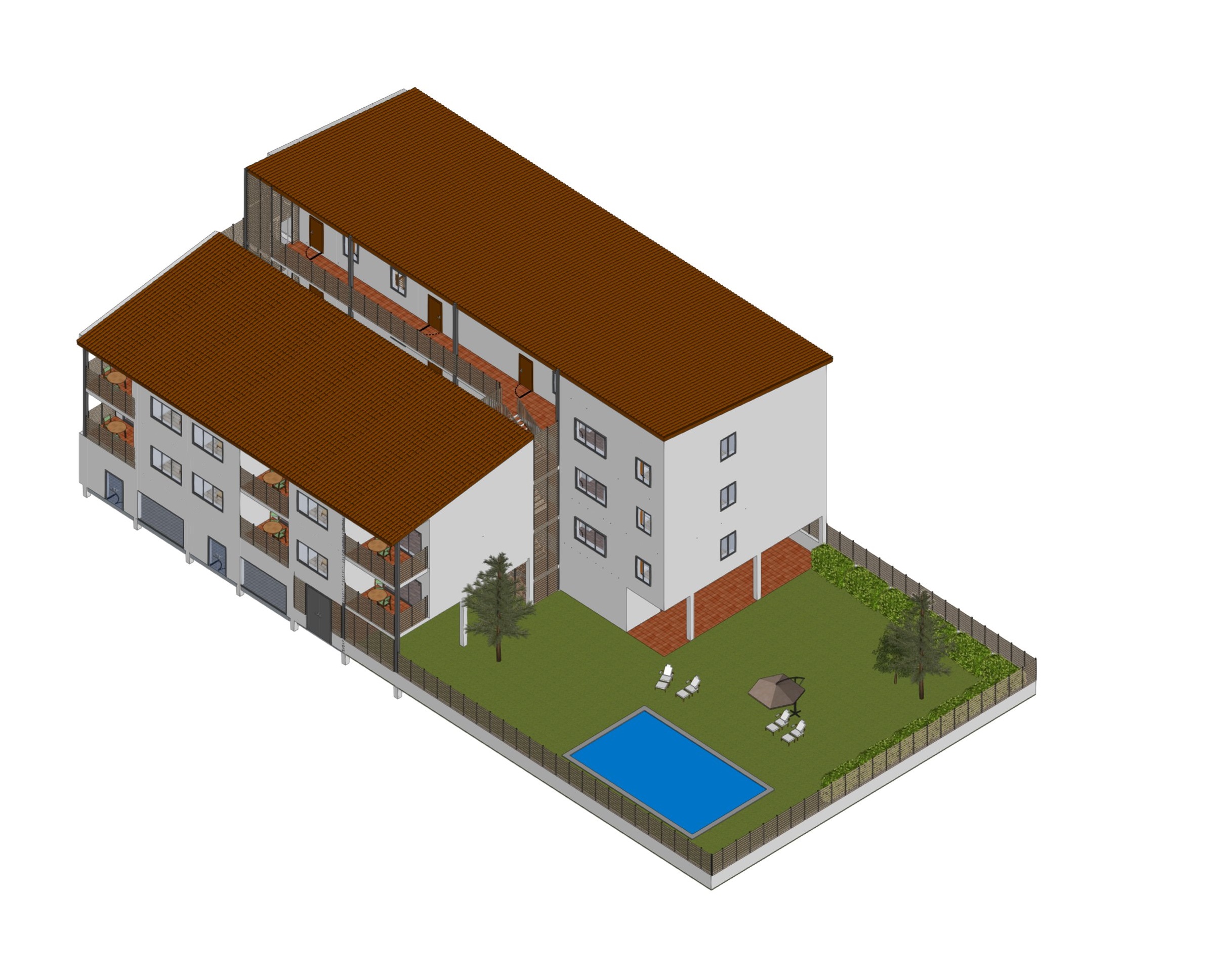
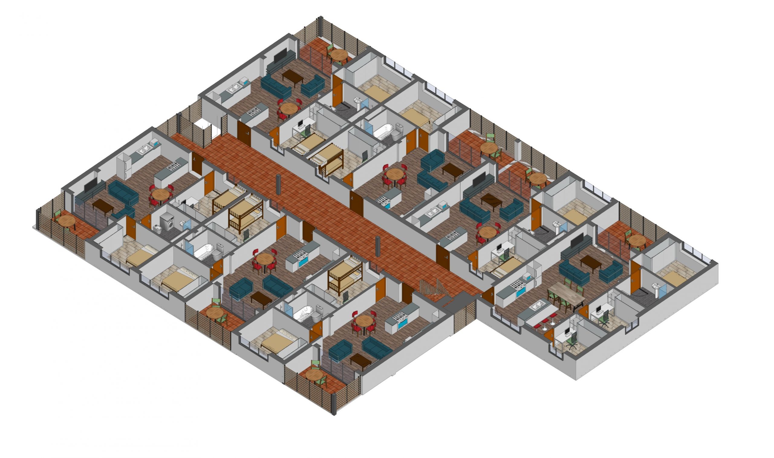
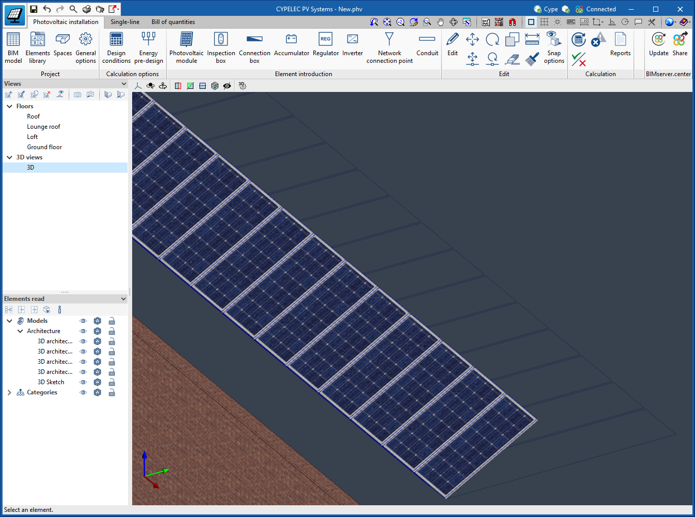
The following images show the number of joints generated in an installation of a 4-storey building with 8 apartments, and the details of an area in this system.

CYPEFIRE Hydraulic Systems

Checkpoint

The checkpoint is a set that includes the alarm valve, shut-off valve and all valves and accessories needed to carry out the control in a sprinkler system.

The maximum size of the system controlled by a checkpoint depends on the risk of the building. According to EN 12845 it ranges from 9,000 to 12,000 m². If the maximum permissible limit is exceeded, necessary measures must be taken.

Users can include and edit this option in the code configuration.

Pressure regulating valve

The pressure regulating valve is used to limit the pressure in the sprinkler system, downstream of its installation point.

This valve can be selected in the main toolbar. To enter it, the diameter and the pressure to be limited must be indicated.

CYPETHERM EPlus

Curtain walls

Curtain wall systems have been added as an option. To use it, a distinction is made in the external wall library between opaque walls, which are those currently in use, and the new glass walls, which are curtain walls.

Under the "Glass wall" option, users must enter the thermal properties of the glazed and opaque surface proportions (glazed ratio) of the curtain wall to be simulated, in a similar way to the definition carried out for windows.

Open BIM Quantities

Managing the visibility of BIM model components

Under the "Quantities of the BIM model" tab in "Open BIM Quantities", a button has been added to the tree of entities making up the BIM project in order to control the visibility of each component in the model view. When using this tool, the visibility of the element or group of elements to which the selected row refers will be activated or deactivated. Thanks to this improvement, it is now much easier to identify or isolate the components of the model in the 3D space.

To determine whether an element should be shown in the scene, the general configuration of the 3D view is also considered. These settings prevail over the application settings, so if a model is hidden, the visibility of its components cannot be controlled from the tree of entities.

Zooming in on the component

A button has been added next to the visibility option ("Manage visibility of BIM model components") in the tree of entities that make up the BIM project, in the "Quantities of the BIM model" tab of "Open BIM Quantities". This option only appears in the rows referring to a BIM model element (it is not shown in the groups) and allows the object to be framed in the 3D view. This makes it easier to locate the components in the space.

"Cut", "Copy" and "Paste" tools in the sets of measurement rules

As of version 2023.a, "Open BIM Quantities" includes the "Cut", "Copy" and "Paste" tools in the sets of measurement rules management panel. These options are available for the list of rules of measurement and, within rules, for the components of the "selection" and "items". 

The application allows users to make multiple selections in the lists so that several rows can be copied or cut at the same time. The cut or copied items can be pasted into a different set of measurement rules.

Exporting and importing rules of measurement

As of version 2023.a, "Open BIM Quantities" can save the rules that make up a set of measurement rules in a file (".bib680"). Two new buttons have been added to the list of measurement rules in order to allow both importing and exporting. This way, the stored rules can be used to compose new sets of measurement rules.

Updated example jobs

The Spanish example job "Proyecto de edificio de viviendas" together with its cost database ("España - Edificio de viviendas") has been updated.

Open BIM Quantities / Applications with a "Bill of quantities" tab

New character for a concept's "Code" field

As of version 2023.a, the "-" character (ASCII-45) can be used in a concept's "Code" field. This modification has been carried out in accordance with the latest update of the standard Spanish FIEBDC-3/2020 format which includes the specifications approved by the Spanish commission CTP that are subsequently ratified by the Spanish FIEBDC association assembly.

Importing cost databases in CSV format

As of version 2023.a, "Open BIM Quantities" and applications with the "Bill of quantities" tab can import cost databases in CSV format. To do so, the "Import CSV" option has been added to the "Import/Export" group in the toolbar for managing cost databases and the project database.

The CSV file must contain the columns with the information for the "Code", " Type ", "Item", "Summary", "Quantity" and "Rate" fields. Users can specify the index of each column from the file import configuration panel. The character set, the index of the first line of text to be imported and the field separator can also be specified.

As with the FIEBDC-3 format files, "Open BIM Quantities" allows users to choose whether to delete the previous data from the cost databases before carrying out the import or updating them.

Duplicate concepts in a cost database

As of version 2023.a, "Open BIM Quantities" and applications with the "Bill of quantities" tab allow cost databases to be generated where an item appears in more than one work section. Items can only be defined in one position, however, they can now be added as a concept in the breakdown of one or more work sections.

This way, different classifications can be established within the same database. If a database in FIEBDC-3 or CSV format has this feature, it can also be imported into the application.

Open BIM Cost Estimator

Updated cost database

The cost database used by the application to determine the total construction cost has been revised. Any projects carried out with previous versions of the program will be automatically updated when they are opened with version 2023.a.

Open BIM Office Furniture / Open BIM Residential Furniture / Open BIM Suspended ceilings

Discontinued programs in version 2023

As of version 2023.a of CYPE software, three of the CYPE applications will no longer be updated. Users who wish to continue using them will have to do so by installing a version prior to 2023.a. However, we recommend using updated versions of other CYPE programs that exceed the features of these three discontinued applications.

The discontinued applications are the following:

  • Open BIM Office Furniture
  • Open BIM Residential Furniture
  • Open BIM Suspended ceilings

The features of these three applications are far exceeded by CYPE Architecture.