Version 2023.a of the "CYPE Connect" and "StruBIM Steel" programs includes the analysis of the rotational stiffness of the connections. With this analysis option, users can obtain as results the resistant moment, initial stiffness, secant stiffness and classification of the connection (rigid, semi-rigid or pinned) of the steel section.
To obtain the "Moment - Rotation" graph, the program carries out an iterative process by analysing the rotation in different load steps. The resistant moment is obtained when any element in the connection (plates, sections, welds or bolts) no longer complies, i.e. its demand capacity ratio is greater than 100%.
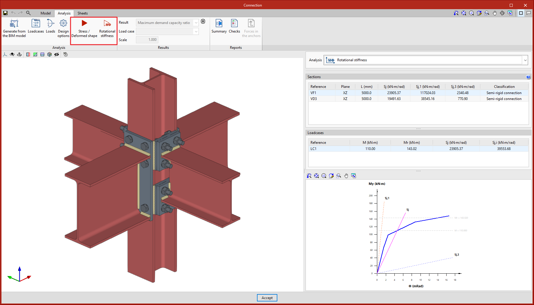
The "Analysis" tab includes the "Rotational stiffness" tool in the top toolbar. If the tool is selected, the rotational stiffness analysis is run.
Furthermore, the "Analysis" tool has been renamed. In previous versions, the "Analysis" button was used to run the stress and deformed shape analysis. This button will now be called "Stress / Deformed shape".
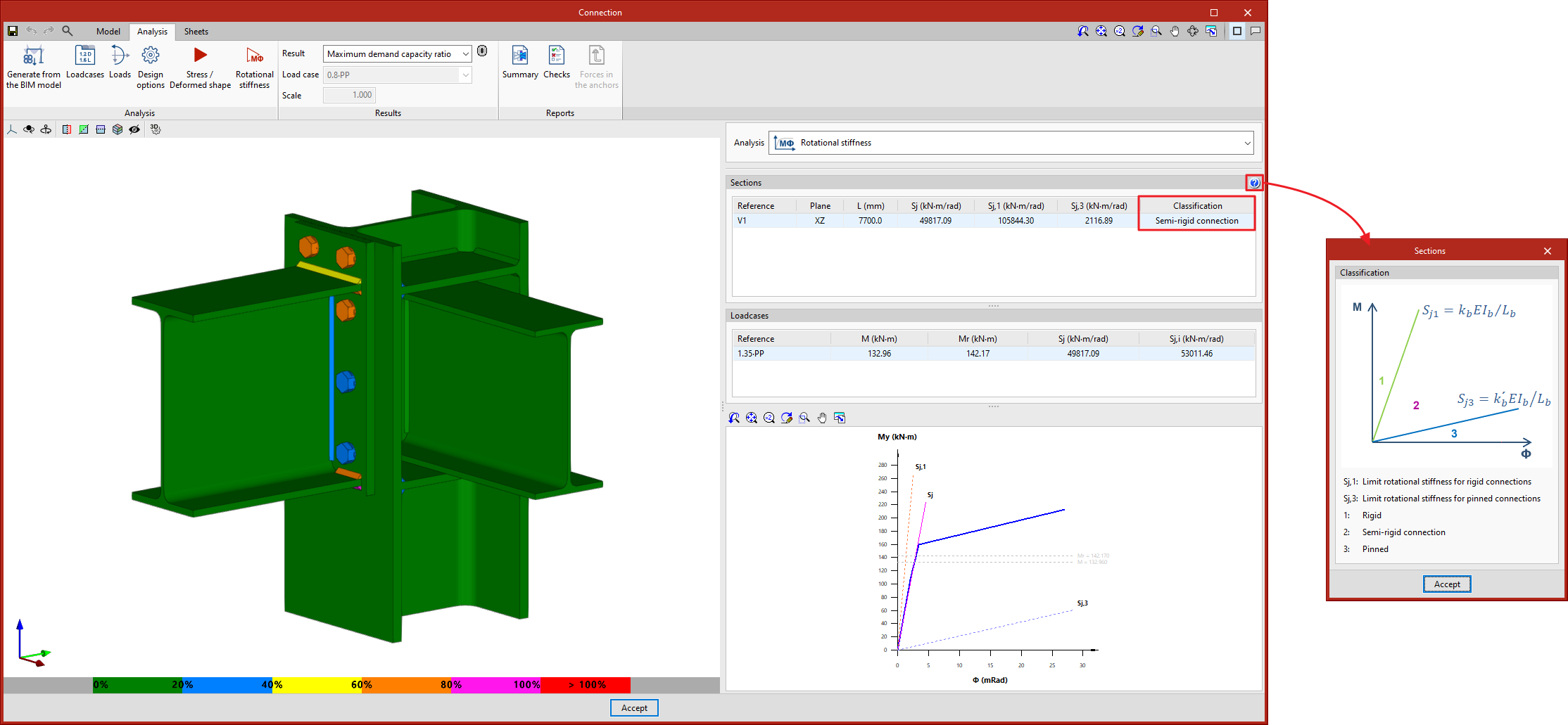
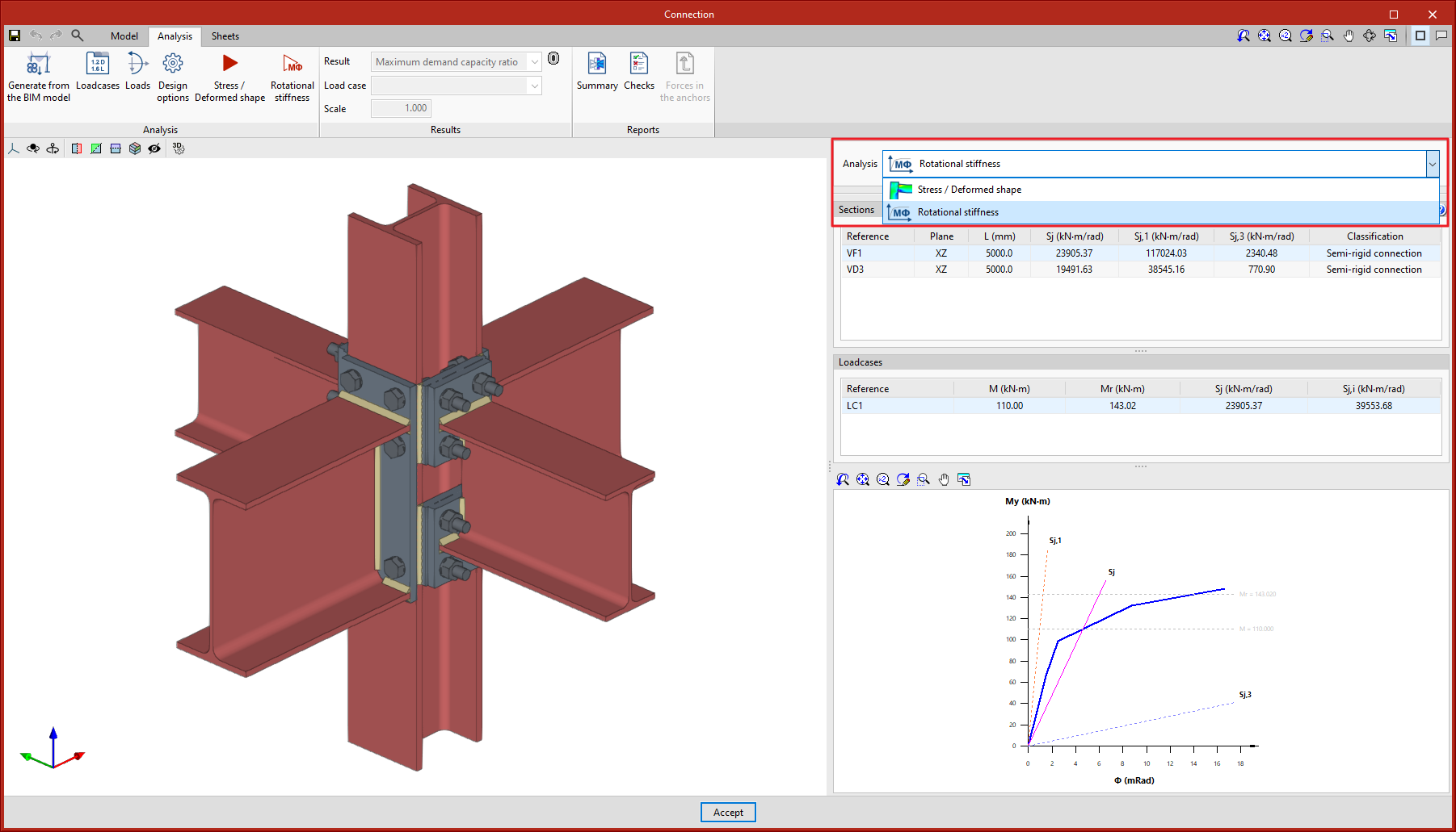
The results can be viewed on the right-hand side of the "Analysis" tab. The top drop-down menu allows users to choose the type of results to be displayed, "Stress/Deformed shape" or "Rotational stiffness". By selecting "Rotational stiffness" the program displays two tables and the "Moment - Rotation" graph.
The first table shows all the analysed bars with their secant stiffness and the connection classification in each plane. The second table shows the load cases analysed for the selected bar. Each load case will indicate the acting moment, the resistant moment, the secant stiffness and the initial stiffness.
The graph shows the curves for "Moment - Rotation", "Acting moment of the selected load case", "Resistant moment", "Ultimate stiffness for rigid connections (Sj,1)" and "Ultimate stiffness for pinned connections (Sj,2)".
As a result of implementing the rotational stiffness analysis, the following changes have been made to existing tools in the program:
- Selecting bars and load cases
Using the "Loads" button, the dialogue box is launched allowing users to select the bars from which the rotational stiffness of their connection is to be analysed. In the centre of this dialogue box, there are two tabs for defining the load tables, per load case. The "Rotational stiffness" tab requests a list of loads, the lengths of the elastic bar in the structural model (used to establish the limit stiffnesses of rigid or pinned connections) and the kb factor.

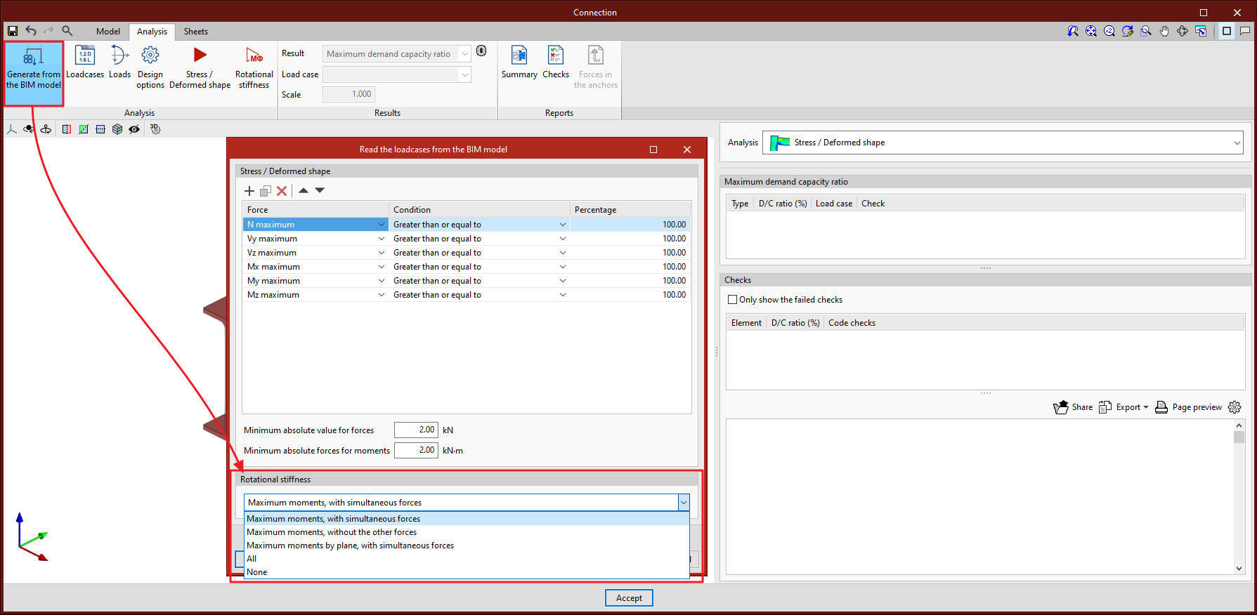
- Generating from the BIM model
By using the "Generate from BIM model" button, the dialogue box for applying filters and importing loads is launched. This version also includes options for importing loads for the rotational stiffness analysis. In addition to the loads, the elastic lengths of the bars in the structural model are also imported, these lengths are necessary in order to classify the connection correctly. Five options are provided for importing load cases depending on the forces:- Maximum moments, with simultaneous forces
Imports load cases that have larger My or Mz moments, either positive or negative, as well as all other simultaneous forces. - Maximum moments, without the other forces
For the maximum moment load cases, only the values of My and Mz are imported. - Maximum moments by plane, with simultaneous forces
Imports load cases with maximum moments and their simultaneous forces per plane, i.e. creates load cases with forces per plane (XY and XZ). - All
Imports all load cases. - None
Does not import any load case.
- Maximum moments, with simultaneous forces
- Classifying the connection
In order to classify the connection as rigid, semi-rigid or pinned, the limit stiffnesses for rigid and pinned connections are first established. Depending on the selected steel code, the initial stiffness or the sectional stiffness is compared with these limits.