Update history
CYPE Connect Classic
Code implementation (IS 800: 2007 – India)
- Published on
- 2015.b
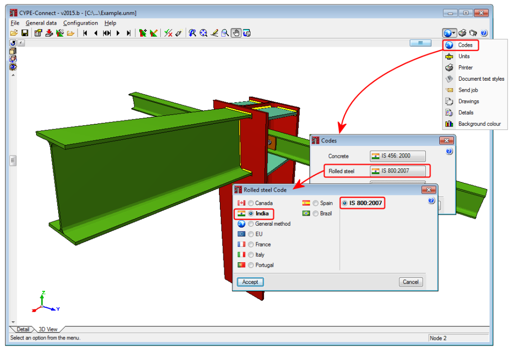
Improved code application. IS 800: 2007 (India)
Indian Standard. General construction in steel – Code of practice (Third Revision).
This code was already implemented in CYPECAD, CYPE 3D, Continuous beams and Portal frame generator to design and check rolled and welded steel bars. Now, in the 2015.b version, the code has been implemented in CYPE-Connect and in CYPE 3D for the design and check of steel connections.
- Published on
- 2015.b
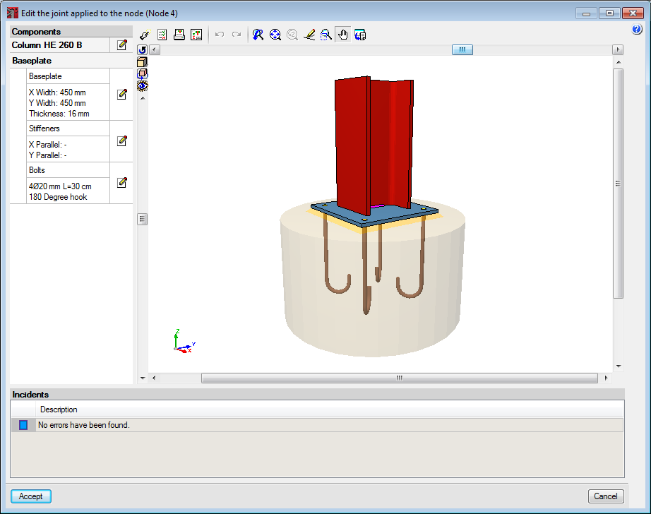
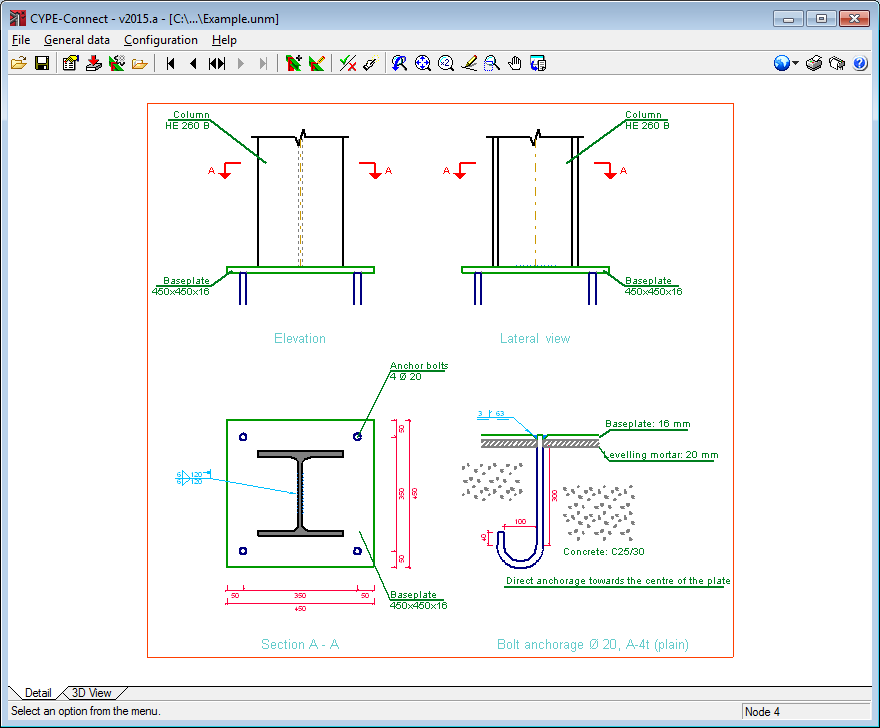
Baseplates in CYPE-Connect
The design and check of baseplates have been implemented in CYPE-Connect. With this implementation, the joints and baseplates that can be designed, checked and edited by CYPE-Connect are the same as those for CYPE 3D (Metal 3D).
As is the case with CYPE 3D (Metal 3D), if the user license contains the Joints I, II, III and IV modules, users can check, design and generate baseplates for rolled and welded steel I-sections. If the users license contains the “Baseplates” module, users can check, design and generate welded baseplates for any steel column arrangement (simple and composite sections; rolled, welded and cold-formed sections).
- Published on
- 2015.a
Implementation of new connection types in CYPE-Connect
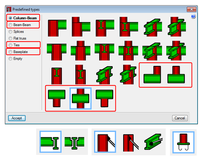
A few types of connections have been implemented, which in previous versions could only be designed by the Joints I, II, III, IV and V modules in Metal 3D (now CYPE 3D):
- Column-Beam connections (continuous beam with column above or below)
- Beam-Beam connections (beam connected to the web of the other beam)
- Splice connections (of hollow structural sections)
- Ties (column with a tie at the flange or web and beam with a tie at the web)
- Baseplates (detailed in the following section )
Therefore, as of the 2015.a version, the types of joints that can be designed, checked and edited by CYPE-Connect are the same as those for CYPE 3D (Metal 3D) .
- Published on
- 2015.a
Code implementation
The following codes have been implemented to design and check steel joints in CYPE-Connect:
- ABTN NBR 8800:2008 (Brazil)
Projeto de estruturas de aço e de estruturas mistas de aço e concreto de edificios. - ANSI/AISC 360-05 (LFRD) (USA – International)
Specification for Structural Steel Buildings. - ANSI/AISC 360-10 (LRFD) (USA – International)
Specification for Structural Steel Buildings. - CAN/CSA-S16-01 (Canada)
Limit States Design of Steel Structures.
These codes were already implemented in previous versions of CYPECAD and Metal 3D (CYPE 3D as of the 2015.a version).
- Published on
- 2015.a
Improved code application. ABTN NBR 8800:2008 (Brazil), ANSI/AISC 360-05 (LRFD) (USA - International), ANSI/AISC 360-10 (LRFD) (USA - International), CAN/CSA-S16-01 (Canada)
- ABTN NBR 8800:2008 (Brasil)
Projeto de estruturas de aço e de estruturas mistas de aço e concreto de edifícios. - ANSI/AISC 360-05 (LRFD) (USA - Internacional)
Specification for Structural Steel Buildings. - ANSI/AISC 360-10 (LRFD) (USA - Internacional)
Specification for Structural Steel Buildings. - CAN/CSA-S16-01 (Canadá)
Limit States Design of Steel Structures
These codes were already implemented in previous versions of CYPECAD and Metal 3D (CYPE 3D as of the 2015.a version). As of the 2015.a version, these design codes have been implemented for the design and check of steel connections in CYPE-Connect.
- Published on
- 2015.a
Joints V. Flat trusses with hollow structural sections
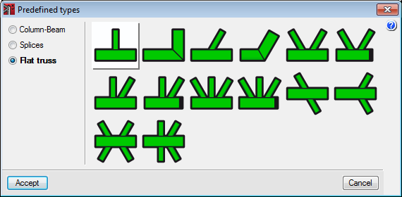
CYPE-Connect was implemented in the previous program version (2014.f). It was created to check, design and generate welded and bolted connections with rolled steel I-sections. The types of joints that could be designed in this first version are those included in the Joints I, Joints II, Joints III and Joints IV modules.
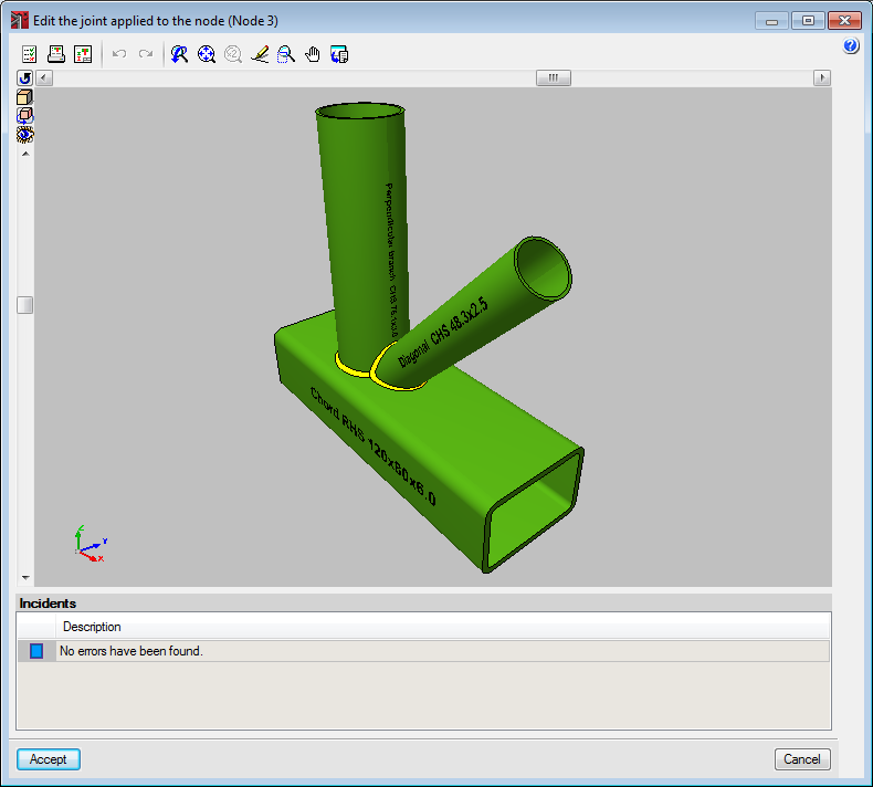
Now, with the 2014.g version, the types of joints corresponding to Joints V – Flat trusses with hollow structural sections have been implemented in CYPE-Connect. Using this module in CYPE-Connect, the program designs, checks and generates the detailing of coplanar joints composed of hollow structural sections, which are most commonly used in flat trusses with circular hollow sections, rectangular hollow sections, square hollow sections and hollow sections composed of two channels welded in a box. The 2014.g has yet to include joint types consisting of a “Splice connection of two aligned hollow sections using bolted front plate”. These will be implemented in an upcoming version.
- Published on
- 2014.g
CYPE-Connect (new program)
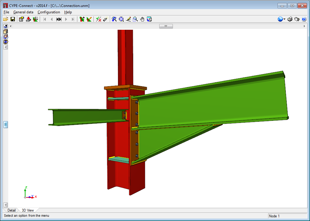
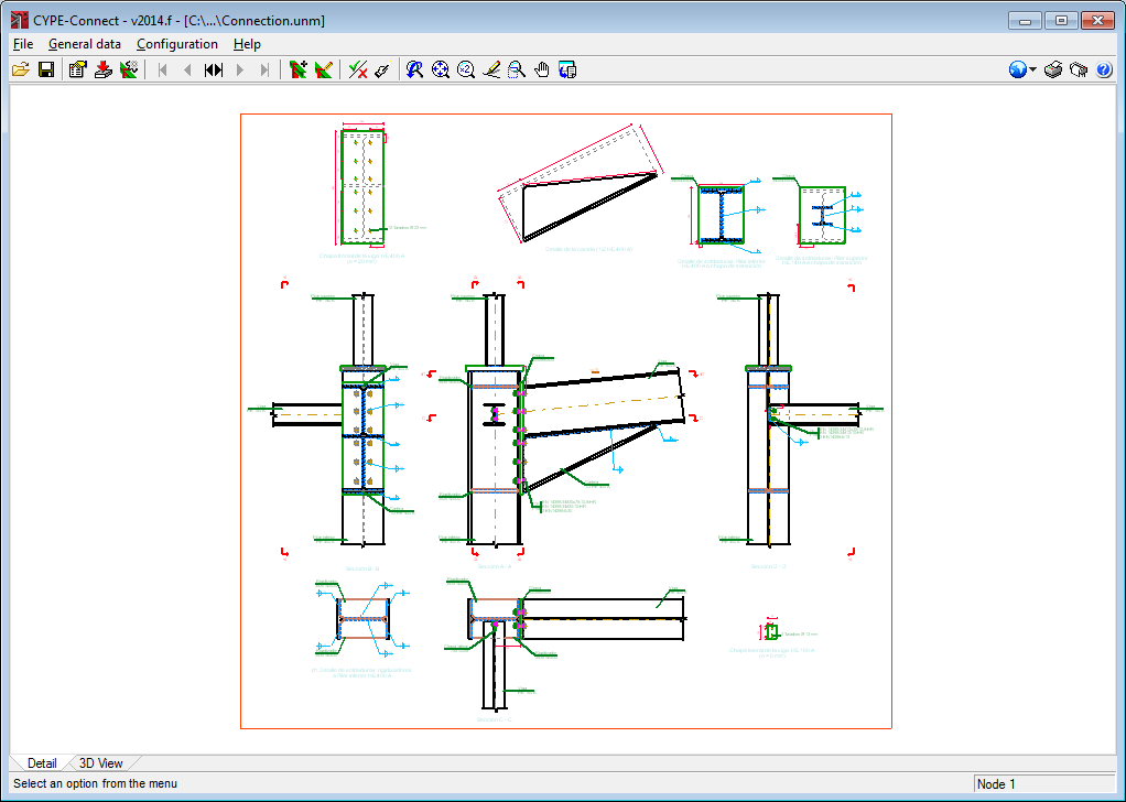
CYPE-Connect is a program to check, design and generate the detailing of welded or bolted steel connections composed of rolled steel I sections.
CYPE-Connect is available in the Structures group of the main CYPE program menu.
The types of joints that are designed are those included in the following joints modules (modules available for use with CYPECAD and Metal 3D), which were implemented in previous program versions:
- Joints I. Welded. Warehouses with rolled and welded steel I sections
- Joints II. Bolted. Warehouses with rolled and welded steel I sections
- Joints III. Welded. Building frames with rolled and welded steel I sections
- Joints IV. Bolted. Building frames with rolled and welded steel I sections
In an upcoming version of CYPE-Connect, the types of joints corresponding to the Joints V. Flat trusses with hollow structural sections module will be included.
Using a data introduction assistant, users select the design code, load combination, loadcases and design options (bolted or welded joint, bolt selection – prestressed or ordinary bolts -, stiffeners). All the data introduced using the assistant can be modified at any time.
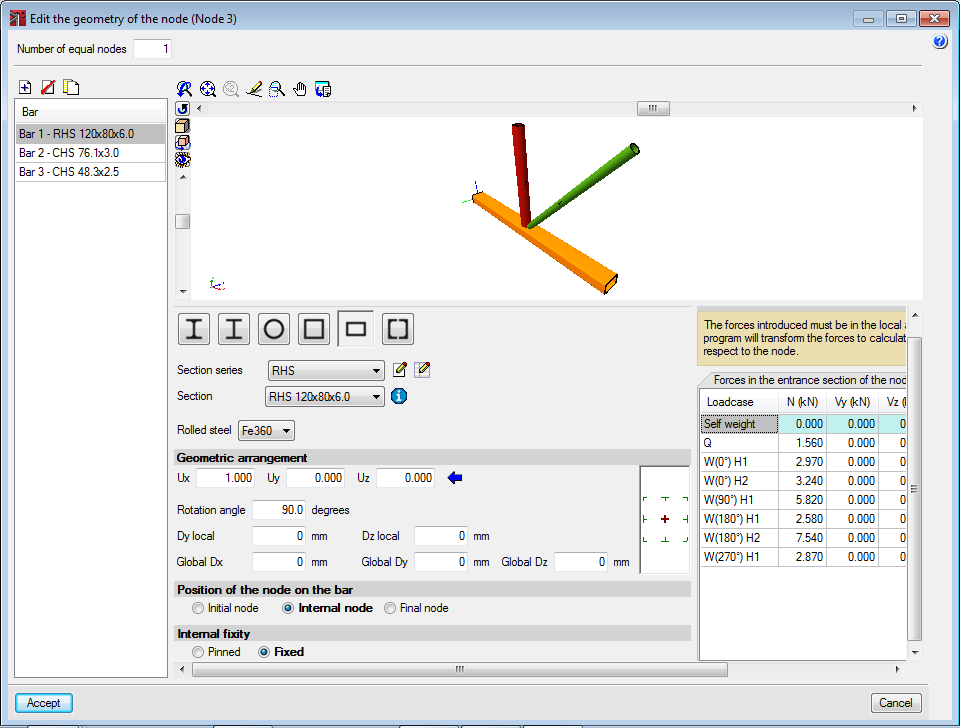
Users can select a joint within the admissible types of each joints module or introduce the connection bars manually. The program will only check and design the connections which form part of the admissible joint types. Forces acting on the node have to be defined by loadcase, the type and series of each bar also have to be defined.
Once the data has been introduced, users can select the option to analyse and design the joint. The program automatically analyses and designs the joint so all the limitations established by the selected code and users are met. Once the design process has concluded, a detailed report of all the checks which have been carried out can be obtained, as well as the on-screen detailing of the joint and corresponding drawing.
CYPE-Connect carries out the same design as CYPECAD and Metal 3D. The new feature of CYPE-Connect which makes it different to the other two programs is that users can edit the designed joint, modify the dimensions and arrangements of the plates, welds and bolts, and finally tell the program to check the joint connections with the changes that have been carried out.
During the check, the program verifies if the connections of the joint meet all the requirements established by the code. Once the joint has been checked, a detailed report can be obtained with all the checks that have been carried out.
Therefore CYPE-Connect allows users to personalise a joint and check that the modifications that have been carried out meet the requirements of the selected code, as well as providing a complete and detailed report of all the checks that have been carried out.
To be able to use CYPE-Connect, users must have a user licence permit to use at least one of the joints modules indicated above. The program analyses, designs and checks the types of joints contained in the modules included in the user license.
A webpage will shortly be available where more details will be provided on the program.
- Published on
- 2014.f

