Version 2027.a includes a tool that automatically routes down conductors through the pylons within the model, based on the previously selected collection of conductors. In addition, the tool automatically incorporates manholes and test clamps, the latter being sourced from manufacturer catalogues available in the Open BIM Database.

Prescription options
Within the "General options" of the "Project" group in the CYPELEC Distribution toolbar, the possibility of modifying the "Prescription options" has been added.
With this option, the documents produced by the program (drawings, reports, quantities, etc.) can be configured, establishing the criteria for generating the descriptions of equipment, materials or services selected from the catalogues downloaded from the Open BIM Database and included in your project.

Checking permissions when sharing a contribution in the BIMserver.center project
As of version 2025.d, when clicking the "Share" option of the apps (before starting the generation of the contribution files), a check is made to ensure that the user is part of the BIMserver.center project team. If the user does not have the appropriate permissions, a warning message is displayed. This prevents the generation of unnecessary files when the user does not have editing rights.

BIMserver.center new features window
As of version 2025.d, the "Project selection" window in the apps connected to BIMserver.center incorporates a new notification system to inform users about the latest new features on the platform.
This space displays relevant messages about new features, enhancements and recommendations related to BIMserver.center. In addition, direct links to documents, tutorials and additional resources will be included to facilitate the adoption of these new features.

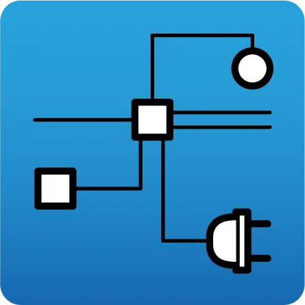
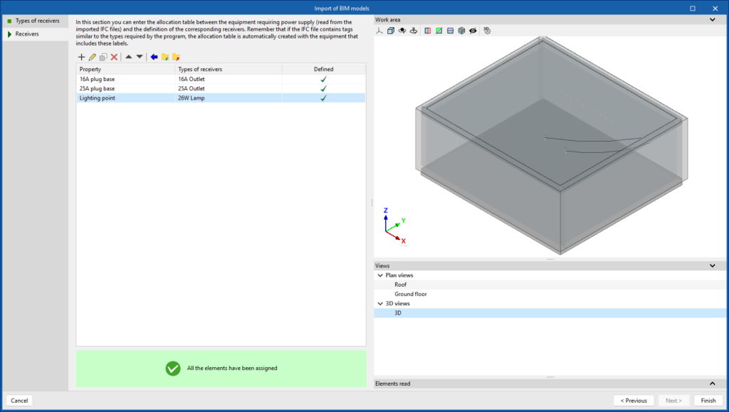
Improved electrical receiver mapping
In the process of creating a new job in CYPELEC Distribution, and whenever there is a link to a BIM project, a wizard is launched for the mapping of electrical equipment from reading IFC files.
The wizard has two stages:
- The first stage creates or imports a list of electrical receivers.
- The second stage assigns the electrical equipment read from the IFC file to the types of receivers in the previously created list.
This assignment table streamlines the process for the subsequent design of the electrical system layout of the project.

Integrating CYPE Lightning into CYPELEC Distribution
As of version 2025.d, CYPE Lightning will be integrated into CYPELEC Distribution.
In the toolbar, a new group called "Lightning protection" is added, with the necessary elements for the design of a lightning protection system by means of an early streamer emission lightning conductor (ESE).
In addition, a receiver is added in the "Project" group of the toolbar called "Protection level" to specify the protection level assigned to the project and on which the lightning protection design depends.
Once the early streamer emission lightning conductor (ESE) has been inserted, the program displays the protected volume and checks whether the volume is sufficient according to the characteristics of the building.

Links to the CYPE website in the apps help menu
In version 2025.c, new options have been added to the "Help" menu of all CYPE apps, providing direct links to key resources on the CYPE website. These options make it easier to access to useful information and Technical Support, improving the overall experience of using the program.
The new options are the following:
- Technical support: This link provides information on the different ways of contacting the CYPE Technical Support team to clarify any queries, obtain customised assistance and solve any problem related to the apps.
- User community: This option provides access to the CYPE user community, where users can share experiences, ask questions and discuss solutions with other professionals using the same tools. This community encourages the exchange of knowledge and best practices, helping to make the most of the program's features.
- Learning resources: This link leads to a collection of learning resources, such as tutorials, manuals, videos and articles, designed to help you understand and use CYPE apps more efficiently. These materials are designed for all levels of experience, from beginners to advanced users, and are an excellent source of information to expand skills and technical knowledge.
These new additions make it easier to access information and provide the necessary support to improve the users' experience with the apps and to encourage professional development.