CYPELEC Networks exports the single-line diagram to the BIM model using a file in IFC format. This file can be imported by "CYPELEC Multiline" from the "BIMserver.center" platform to represent the multiline diagram of the installation.


CYPELEC Networks exports the single-line diagram to the BIM model using a file in IFC format. This file can be imported by "CYPELEC Multiline" from the "BIMserver.center" platform to represent the multiline diagram of the installation.
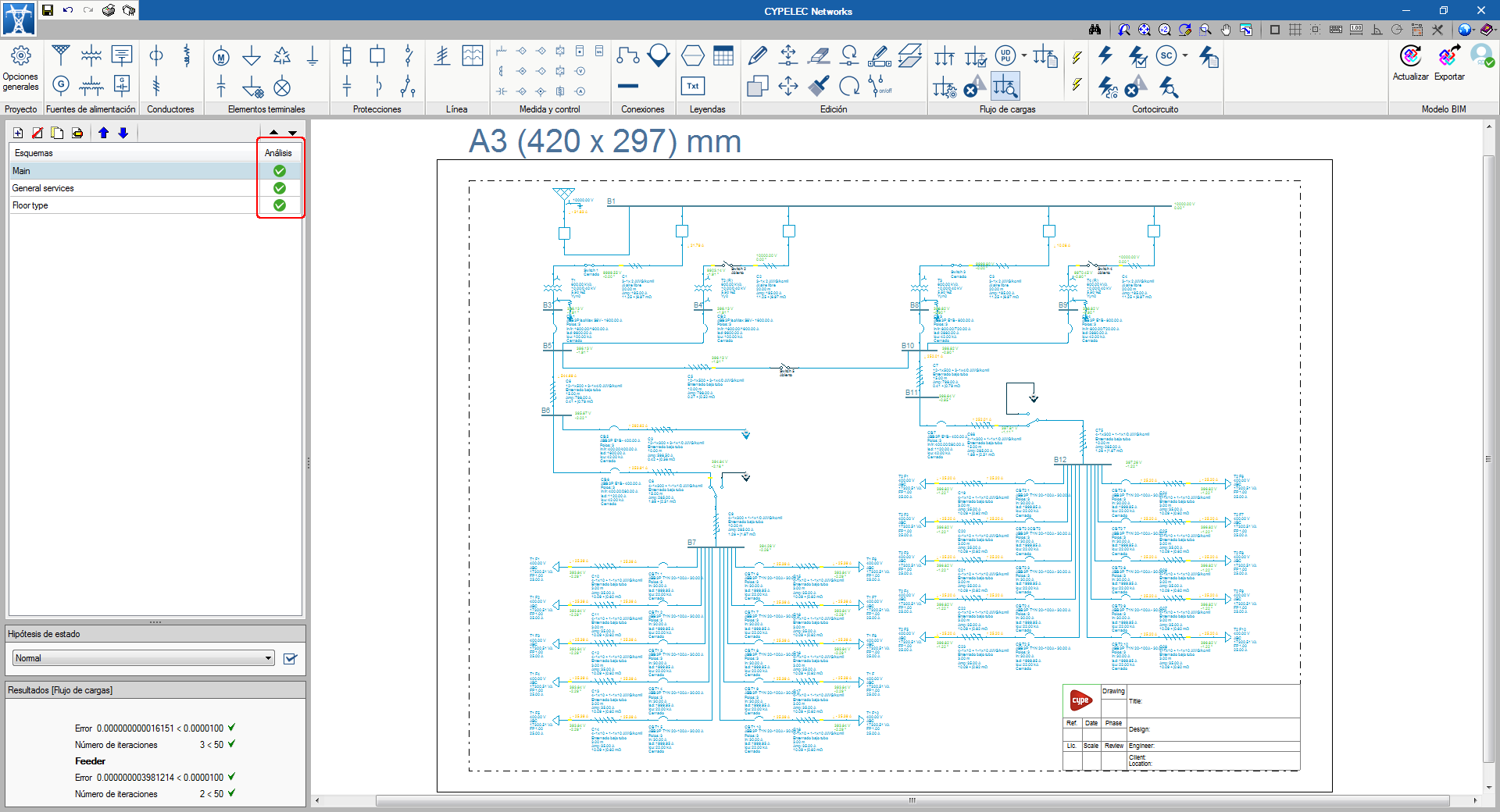
When the load flow or short circuit analysis is launched, all the diagrams of the project are designed, not only the one that is active.
To represent the final design status, a column is added to the right of the diagrams, so users can quickly view the result.
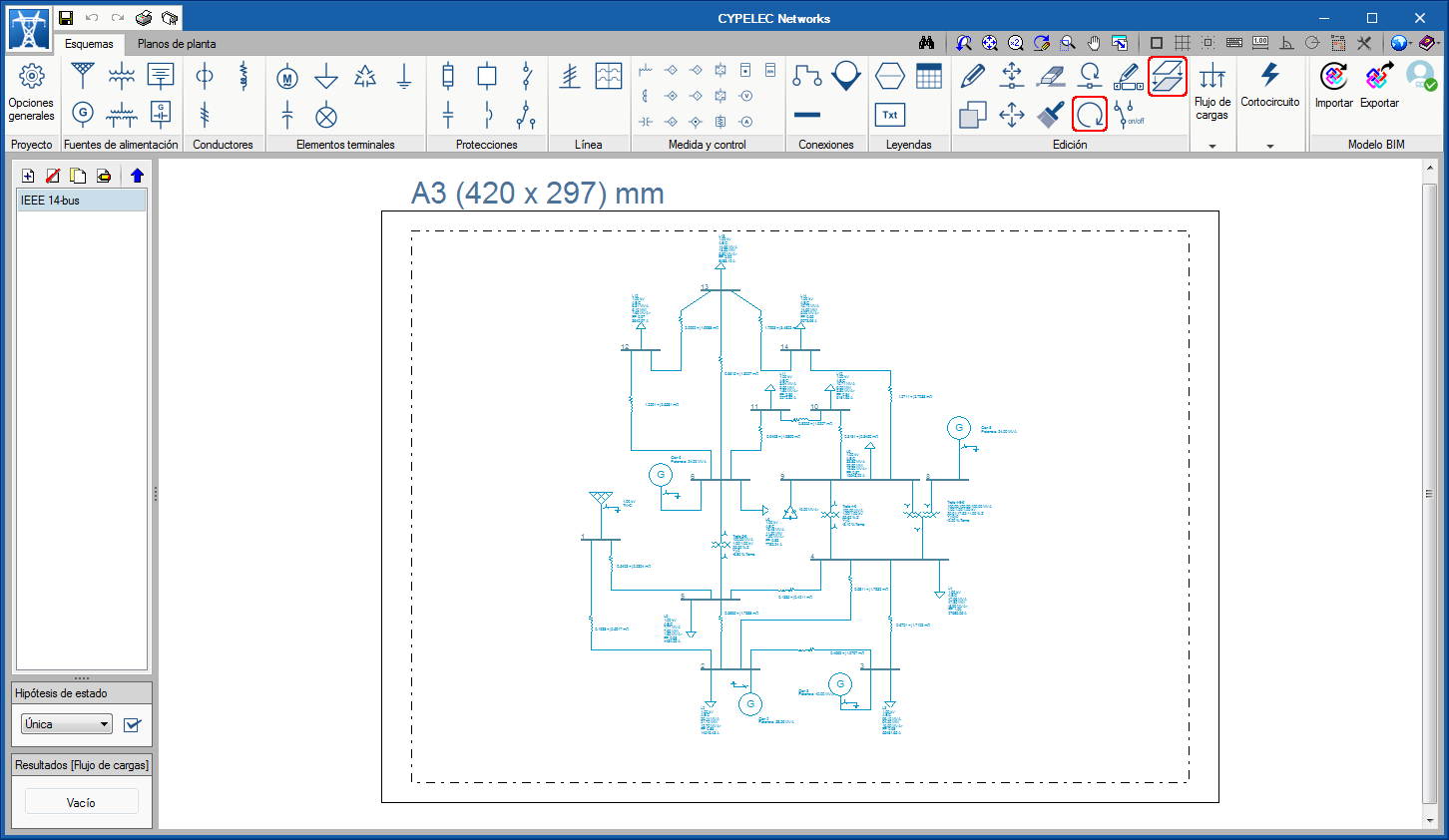
In the “Edit” block of the CYPELEC Networks toolbar, two new options have been added: “Rotate group” and “Copy to another diagram”:
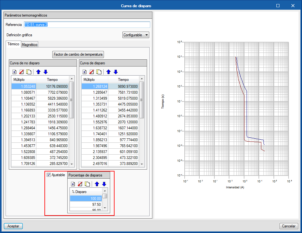
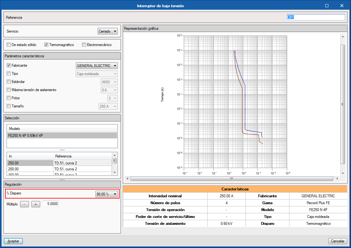
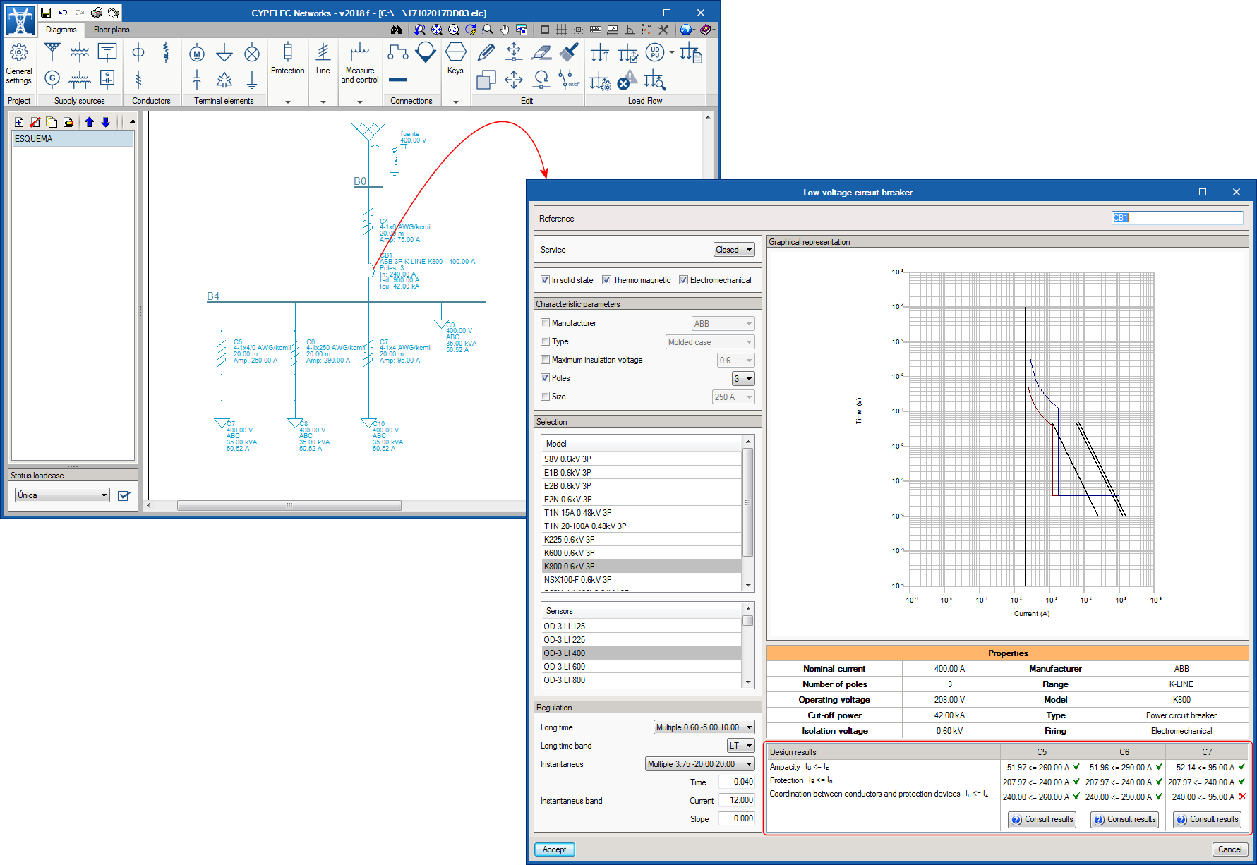
When the adjustment of the thermal trigger in the curve of a thermomagnetic switch is to be activated, it can be selected when this switch model is introduced in the electrical installation.
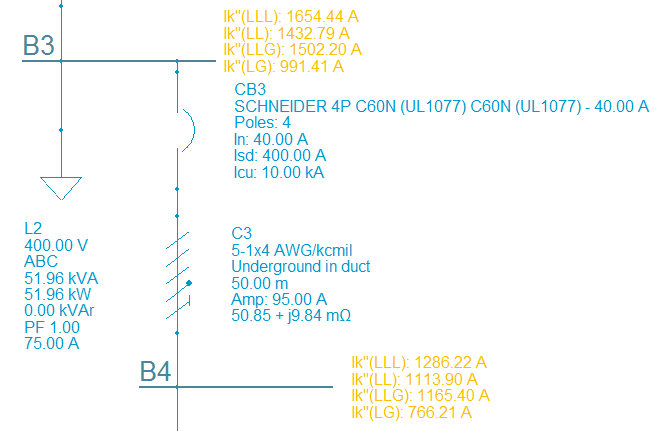
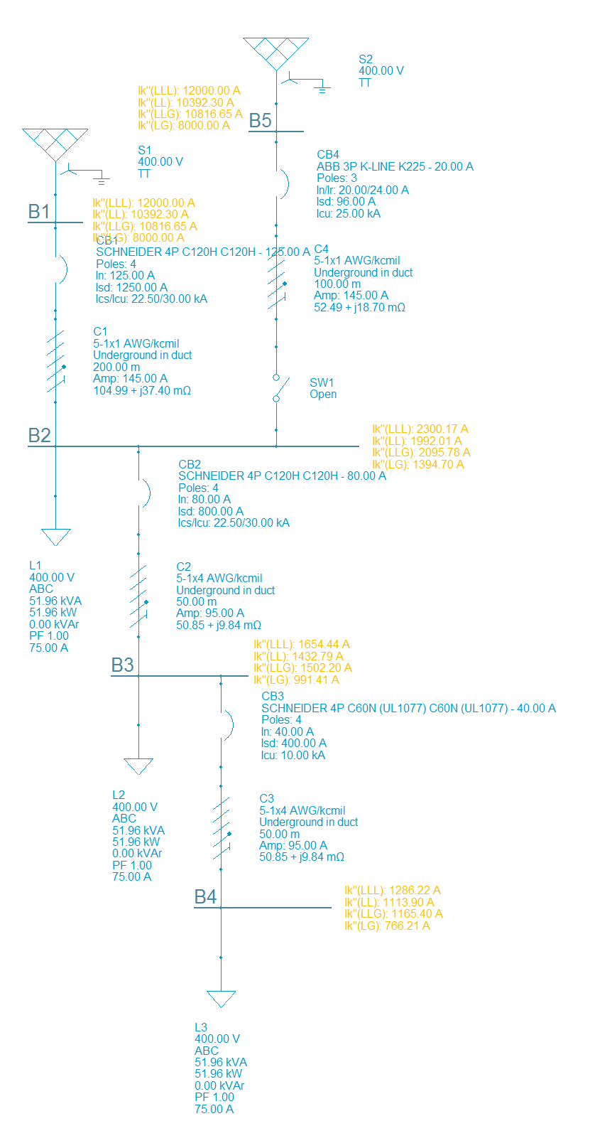
A cable or transmission line that is situated between two buses. CYPELEC Networks calculates the short circuit currents in both buses, i.e. calculates the current at either end of the cable.
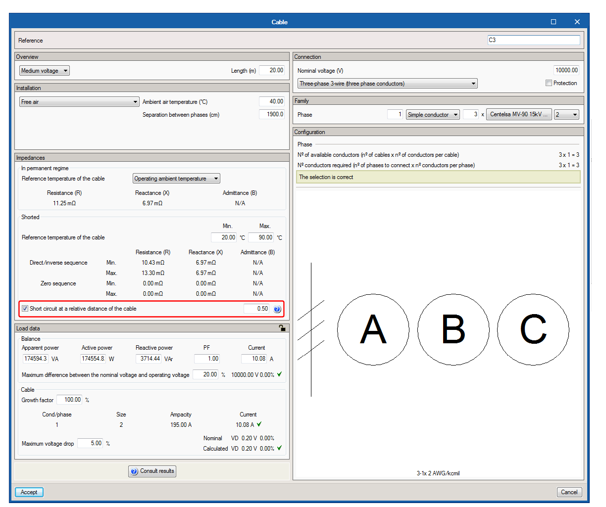
The program has an option that allows users to calculate short circuit currents at a relative position of the cable as well as at its ends. To do so, the “Short circuit at a relative distance of the cable” option must be activated and users have to indicate the relative position (between 0 and 1) where the short circuit occurs. After the analysis, the program will display the results of this short circuit next to the representation of the cable or transmission line.
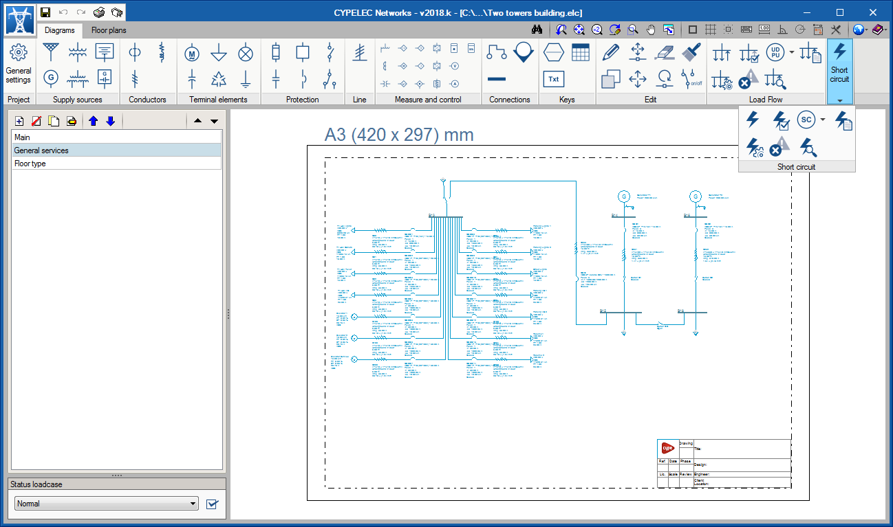
With the 2018.k version, the calculation of short circuit currents in accordance with the IEC 60909 international code is added to the calculation of load flows.
The “Short circuit” section has been created in the toolbar of the program, which includes all the options that allow users to configure and obtain the design results of the short circuit currents:
Calculation of the short circuit current ![]()
Calculates the initial symmetrical short circuit current in the electrical installation for the following short circuit types:
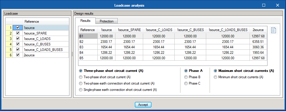
Analysis of short circuit loadcases ![]()
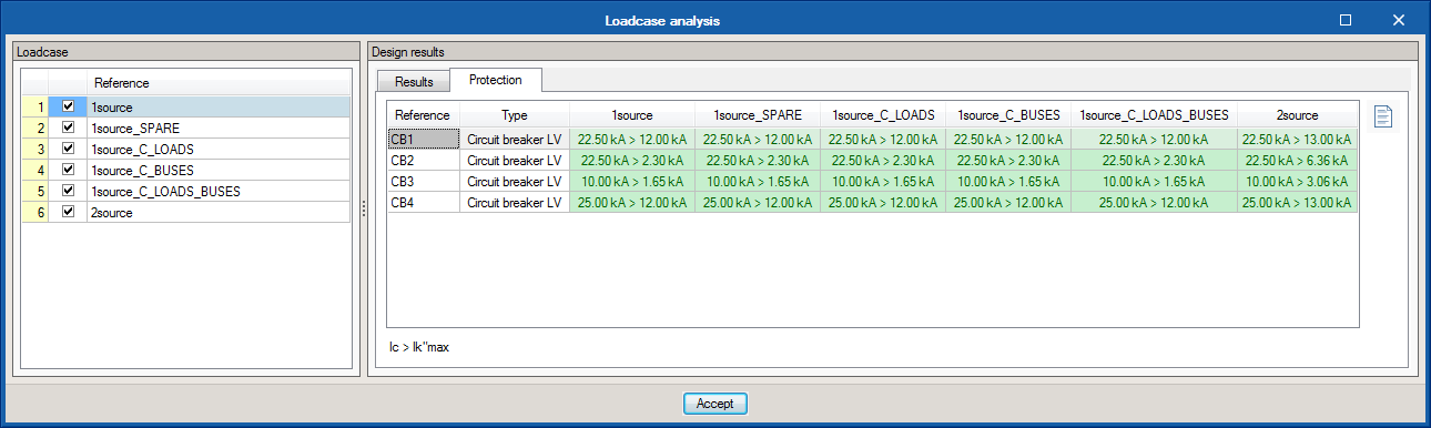
With this option, a dialogue box opens where users can view, for each loadcase, two tables which display the design results of the short circuit currents (Results tab) and the short circuit check for switches (Protection tab).
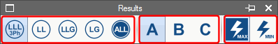
Results view ![]()
This option opens a new toolbar that allows users to configure the view of the results on-screen. Users can choose to:
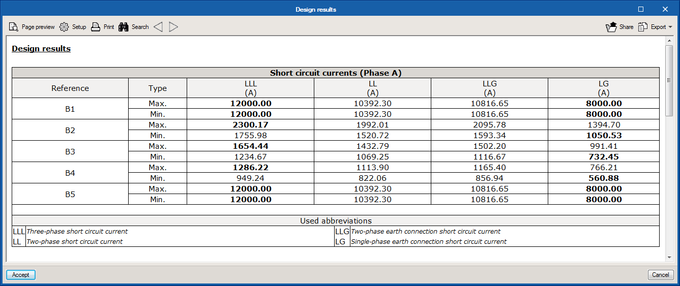
Results report ![]()
Displays a table containing the short circuit currents, with the maximum and minimum values for each bus displayed in bold. It should be noted that the type of short circuit that gives rise to the highest current depends on the direct sequence, inverse and homopolar short circuit impedance of the system.
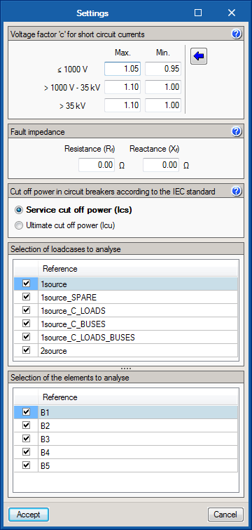
Design settings ![]()
This button opens a dialogue box containing 5 sections:
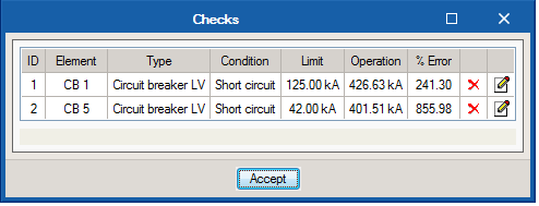
Checks ![]()
This option displays a panel containing the short circuit checks that fail. One of these is the validity of the short circuit switches that have been installed.
Show/Hide results ![]()
Shows or hides the short circuit results on-screen.
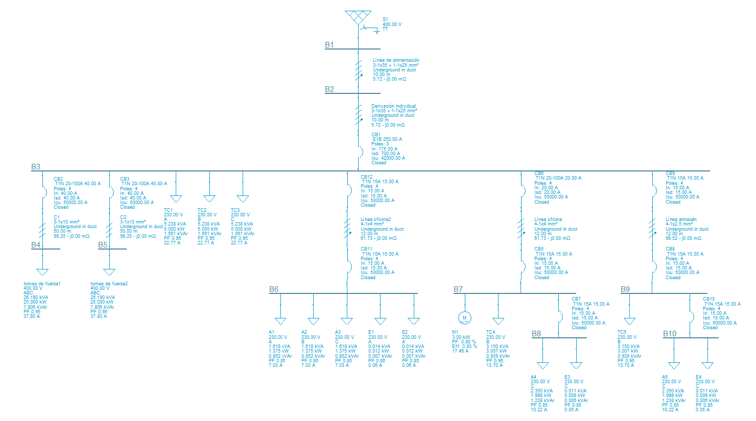
If a common circuit breaker protection is provided for several lines (as shown in the figure), in the panel corresponding to the protection, the checks are displayed with all the cables that are further down the line (in the example, the checks of the common protection are also listed with the three cables that follow it).
Once the load flow analysis has been completed, the “Checks” button ![]() , contained in the “Load flow” block of the top toolbar, provides users with a list of the elements that fail in the installation.
, contained in the “Load flow” block of the top toolbar, provides users with a list of the elements that fail in the installation.
A column has been added to this Checks panel, for each element, where users can open and edit the element in question and solve the situation that causes the element to fail in a quick and accessible manner.
Once the element is edited using this method, its row will be displayed in red and the panel will then indicated that a new analysis has to be launched to update the results.

The project example “General industry” has been added corresponding to the electrical installation of an industry.
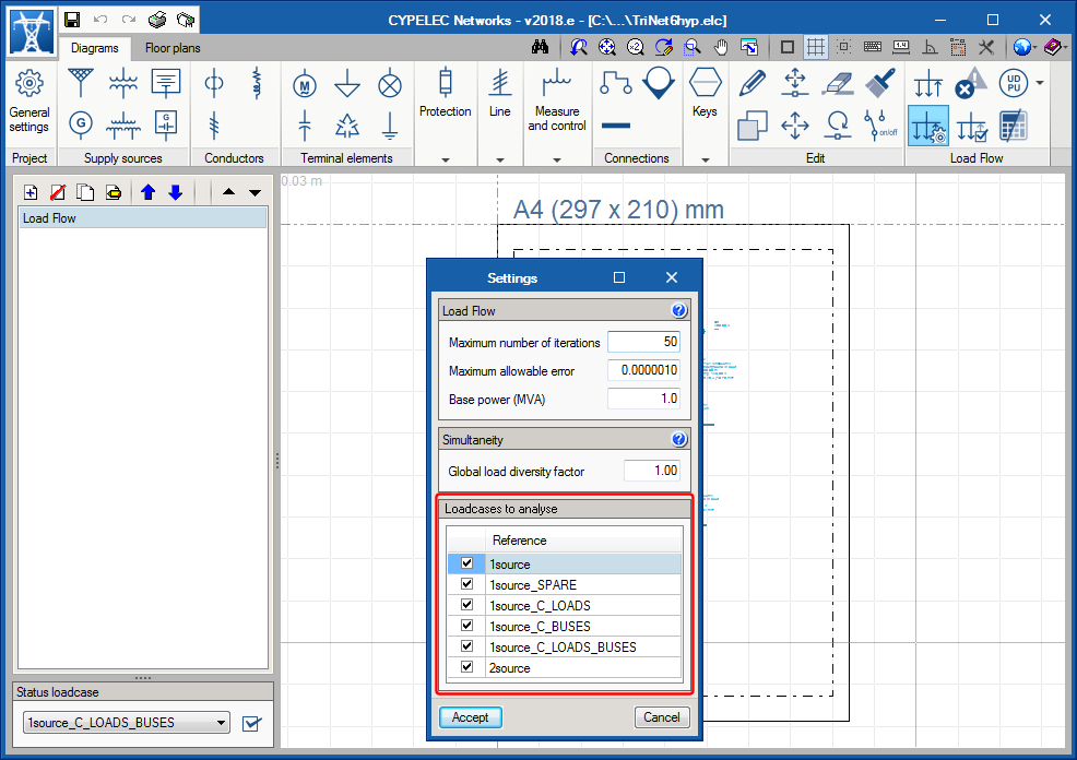
In the “Settings” option of the “Load flow” section of the toolbar, users can now select the loadcases which are to be analysed. This selection affects the analysis process of the loadcase in such a way that only the properties and results of the loadcases selected in this section will be referred to.