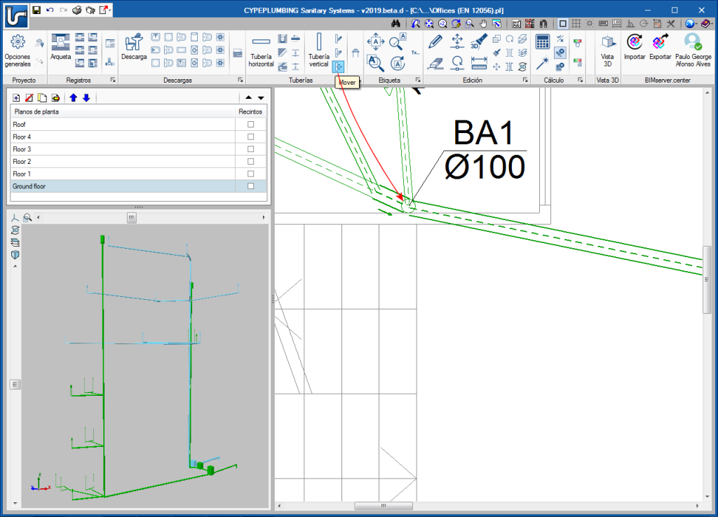
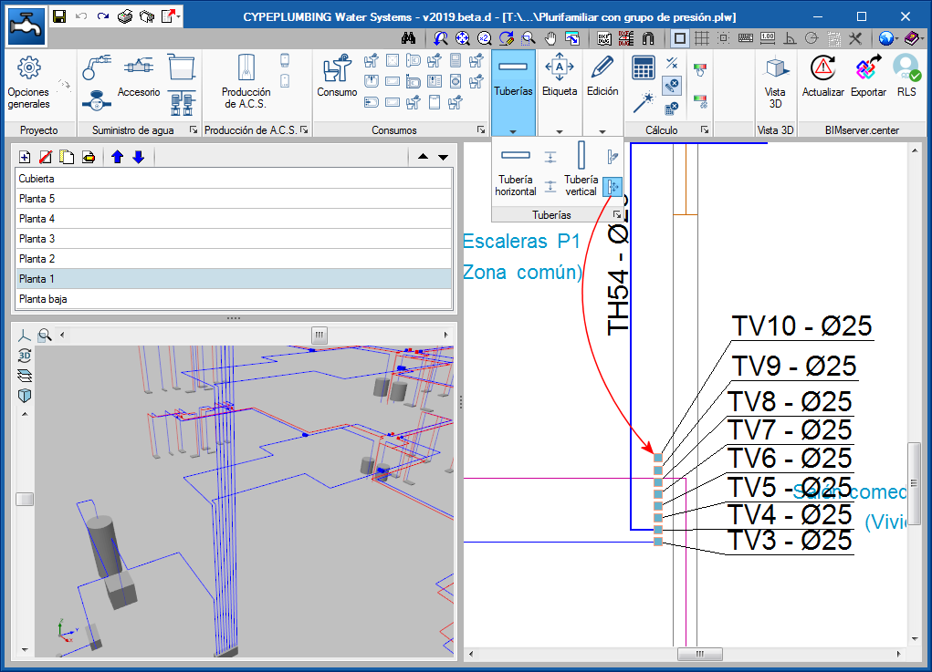
Update history​​

CYPEPLUMBING

Tag management in drawings has been improved. Now, tags follow pipes or their associated element when they are moved.

Additionally, the tool “Rotate tag” New modules and programs. CYPEPLUMBING Water systems. Click to enlarge the image has been added in the “Label” menu.

The same tool has been added in CYPEPLUMBING Solar Systems.

A new icon New modules and programs. CYPEPLUMBING Water systems. Click to enlarge the image has been added to the “Pipes” toolbar, which users can use to completely move a drainpipe, from its initial floor to the last. In previous versions, they could only be moved using the generic “Move” tool New modules and programs. CYPEPLUMBING Water systems. Click to enlarge the image from the “Edit” menu, which continues to exist to move any element. However, when this tool is used to move drainpipes, only the span of the pipe of the floor that is shown on-screen is moved.

In both cases, only the drainpipe is moved and not the horizontal pipes that connect to it.

The tool to move complete vertical drainpipes (New modules and programs. CYPEPLUMBING Water systems. Click to enlarge the image) has also been implemented in CYPEPLUMBING Water Systems and CYPEPLUMBING Solar Systems.

As of the 2018.l version of CYPEPLUMBING Water Systems, users can define the maximum distance between the hot water production equipment and the consumption point. If the check is activated and the distance is defined, the program will display a warning at the consumption points that exceed it.

This check is activated in “General options > Analysis and drawing options > General checks”

The check is deactivated by default. In an upcoming version, it will be activated with the value that is established in the selected code and users will be able to deactivate or edit it to modify the limit.

Specific simultaneity criteria

As of the 2018.l version of CYPEPLUMBING Sanitary Systems, users can define specific simultaneity criteria for a type of horizontal or vertical pipe, different to that which has been defined for all the installation in “General settings > Analysis and drawing options > Calculation options > Simultaneity”.

The specific simultaneity criteria are defined in: General settings >Design and check options to be carried out > “Horizontal pipes” or “Vertical pipes” > Select or define a type of pipe > “Design and check data” section > activate “Apply specific simultaneity criteria”.

Limit chamber inlet heights

The possibility to “Limit the height of the chamber inlet above its base” has also been implemented. This option can be activated and the limit can be defined individually for each type of “Inspection box” in the “Dimension properties” section of the “Inspection box” dialogue box (General settings > design and check options to be carried out > Inspection boxes > Selection or definition of a type of inspection box).

This option is deactivated by default and it is users that must activate it and indicate the limit value. In an upcoming version, it will appear activated in accordance with the values established in the selected code and users will be able to deactivate or edit it to modify the limit.

Maximum distance between cleanouts and cleanouts at pipe spans with a change of direction

As of the 2018.l version, CYPEPLUMBING Sanitary Systems allows users to define the maximum distance that must exist between horizontal pipe cleanouts and cleanouts at pipe spans with a change of direction.

To do so, the “Horizontal pipe” dialogue box (General settings > Design and check options to be carried out > Horizontal pipes > select or define a type of horizontal pipe) has been reorganised; the “Design and check data” section now consists of three tabs “General data”, “Analysis methods to use” and “Additional checks”. The latter tab contains the two cleanout checks that have been mentioned (Maximum distance between cleanouts and Cleanouts in the changes in direction of the pipe).

These checks can be selected for each type of horizontal pipe that is defined in the project.

The program emits warning when the checks fail for the horizontal pipes for which they have been activated.

These checks are currently deactivated by default and users must activate them if they wish. In an upcoming version, they will appear activated if they are contemplated in the selected code. Users will be able to freely activate, deactivate or modify the maximum distance.

Maximum distance between water seals and ventilated sections

As of the 2018.l version, CYPEPLUMBING Sanitary Systems allows users to define the maximum distance that must be present between the discharge water seals and the closest ventilated section.

This check is located in the “Design and check data” section of the “Discharge” dialogue box (General settings > Design and check options to be carried out > Discharges > selection or definition of a type of discharge) and can be defined individually and with different values for each type of discharge. Users establish the maximum distance for each slope interval they wish to define in a table.

The program will emit warnings when this check fails for the types of discharges for which it has been defined.

This check is currently deactivated by default. Users must activate it, if it is to be contemplated. In an upcoming version, the check will appear activated with the values corresponding to the selected code. Users can modify these values or deactivate the check.

The 2018.l version of CYPEPLUMBING Sanitary Systems can calculate the excavation volumes of inspection chambers and horizontal pipes. For the program to be able to carry out this calculation, users must define:

  • Geometric properties of the transverse excavation profiles
    Several transverse profiles of inspection chambers and horizontal pipes can be introduced and included in a library to use them in different projects.

    They are defined in “General settings > Analysis and drawing options > Calculation options > Excavations”.

    There are no predefined profiles by default; users must create them. In an upcoming version, predefined profiles will exist with the properties that are specified in the selected code. Users will be able to edit them and add new profiles.
  • Selection of types of inspection chamber and horizontal pipes with excavations
    Users must select the transverse excavation profile to be used depending on the type of inspection chambers and horizontal pipes for which the soil must be excavated.
  • Introduction of inspection chambers and horizontal pipes
    When users introduce the types of inspection chambers and horizontal pipes indicated in the previous step, the initial and final elevations of the ground must be introduced, and the program will automatically assign the excavated volume based on these elevations, the data of the transverse section of the excavation and the inlet and outlet elevations of the inspection chambers. The excavated volume that is calculated can be modified manually. Users can block the initial and final elevations of the ground, and the excavation volumes, so they do not change in future result updates.

The program displays the longitudinal profile of the horizontal pipes on-screen, which can be printed or exported to different drawing format files.

The quantities report of the network includes the excavation volumes of the inspection chambers and horizontal pipes for which the previously mentioned data has been defined.

Users can now add a series of complementary checks that modify and complement the specific design options and checks of the selected code.

Since the program’s first version, the design options and checks of the selected code are defined in the “Design and check options to be carried out” section of “General settings”. In the 2018.k version, the “General checks” button has been added to the “Analysis and drawing options” section of the “General settings” dialogue box, which opens a panel with same name, that allows users to configure more design and check options:

  • General checks
    • Positioning of the traps in series
      By activating this option, users can check that these elements have not been placed in series.
    • Minimum free height
      The field “Minimum free height” has been included in the definition of each floor. By activating the “Minimum free height” option in the “General checks” dialogue box, the program will check that the lowest point of each pipe span of each floor does not exceed the minimum free height that has been defined.
  • Calculation options
    In this section of the “General checks” panel, users can create alternative options to those that have already been defined in “Design and check options to be carried out”. Several design option groups can be configured. Once defined, they will not be applied to the design of the installation until they have not been assigned by users using the “Design options” button of the “Project” section of the top tool menu.

Users can now add a series of complementary checks that modify and complement the design and check options of the selected code.

Since its first version, the design and check options of the selected code are defined in the “Design and check options to be carried out” section of the “General settings” dialogue box. In the 2018.j version, the “General checks” button has been added to the “Analysis and drawing options” section of the “General settings” dialogue box, which opens a panel of the same name, in which users can configure more design and check options:

  • General checks
    • Positioning in series of the wetroom valves
      By activating this option, users can check that these valves are not connected in series.

  • Design options
    In this section of the “General checks” section, users can create alternative options to those that are already defined in “Design and check options to be carried out”. It is possible to configure several design option groups. Once defined, they are not applied to the design of the installation until users assign them using the “Design options” button of the “Project” section of the top tool menu.

The 2018.j version of CYPEPLUMBING Water Systems includes two visualisation modes that affect the 2D and 3D views of the installation. For this, the “Visualisation mode” section has been added to the “Representation options” panel (General settings > Analysis and drawing options > Representation options). This section allows users to activate or deactivate the “Single filament” option for the 2D and 3D views separately. When activated, a single filament view is displayed, and when deactivated, a volumetric view can be seen. The properties of these views are detailed below:

  • Single filament view
    This is the view that was available as of previous versions and that which is active by default. With this view, the pipes of the installation a represented as a line on drawings, and in the 2D and 3D on-screen views.
  • Volumetric view
    The pipes of the installation are represented in their real magnitude on drawings and in the 2D and 3D views.

In the 3D views, the remaining elements of the installation do not vary when either view is selected, and are represented with a volume surrounding their real appearance.

In the 2D views, pressure sets, tanks and hot water production equipment are represented with their symbols in the “Single filament visualisation” (which may or may not coincide with their real appearance). In the “Volumetric view”, these elements are represented with their symbols and also with their real outline.

When the pipes are exported to the BIM model, these are exported as single filament elements, if the single filament option of the 3D view is activated or as volumetric elements if it is not.

The Project documents manager, which was implemented in the previous program version (2018.i), allows users to generate a document, with its index, which includes reports selected by users.

As of the 2018.j version, the manager allows users to configure several documents of the same project with different contents (e.g. a document that includes quantities and another that does not). This way, users do not have to change the contents of the document to generate more than one type, and can configure a collection of documents with the required contents.

The Project documents manager, which was implemented in the previous program version (2018.i), allows users to generate a document, with its index, which includes reports selected by users.

As of the 2018.j version, the manager allows users to configure several documents of the same project with different contents (e.g. a document for wastewater and another for rainwater, one that includes quantities and another that does not). This way, users do not have to change the contents of the document to generate more than one type, and can configure a collection of documents with the required contents.

The program generates, in the 3D view, any vertical spans that join two elements introduced in the same floor but with different elevations. This already occurred as of the 2018.g version for consumption elements. These elements are introduced in the same floor plan as the pipe that feeds them. In the 3D view they appear joined by a vertical span without the need to have to manually introduce it.

Now, these vertical spans are also generated between pipes with different elevations or between other elements to which users assign a different elevation to that of the plane along which the pipe runs (connections, meters, tanks, pressure groups ...).

The vertical spans that are generated automatically by the program are drawn in the 3D view in a slightly lighter colour than the pipes and verticals spans introduced by users. The vertical spans that are generated will have the same diameter as the pipe from which they descend. If users wish to modify their diameter, the vertical span must be introduced manually using a vertical pipe.

In the attached image, the vertical spans that have been generated automatically are marked with a red circle (both in the 3D view and in the plan view).