A tool has been added with which users can modify the coordinate system of the application. This tool is being implemented in several applications. In the 2021.a version, the tool is available in the following applications:
- IFC Builder
- CYPECAD MEP
- CYPEHVAC
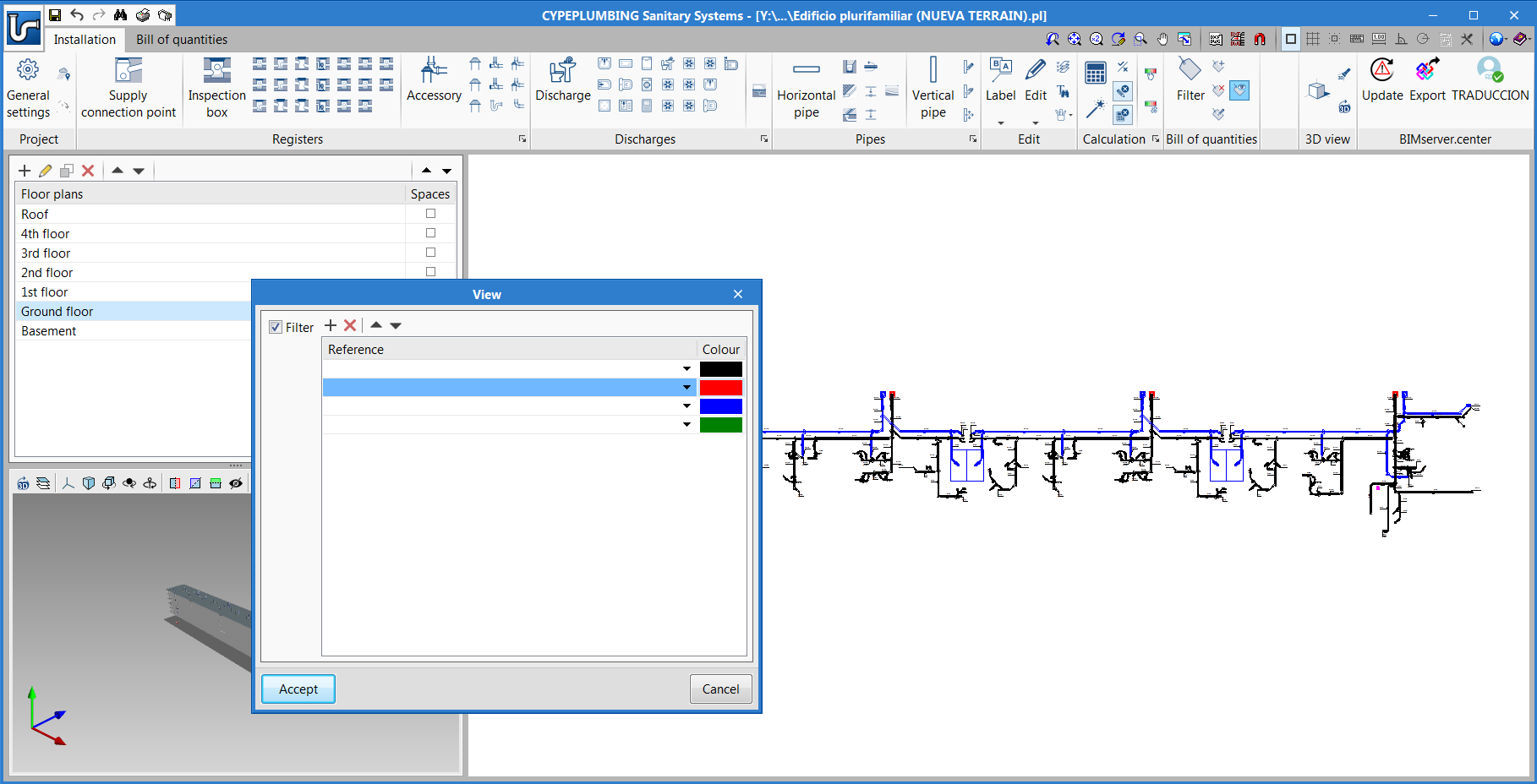
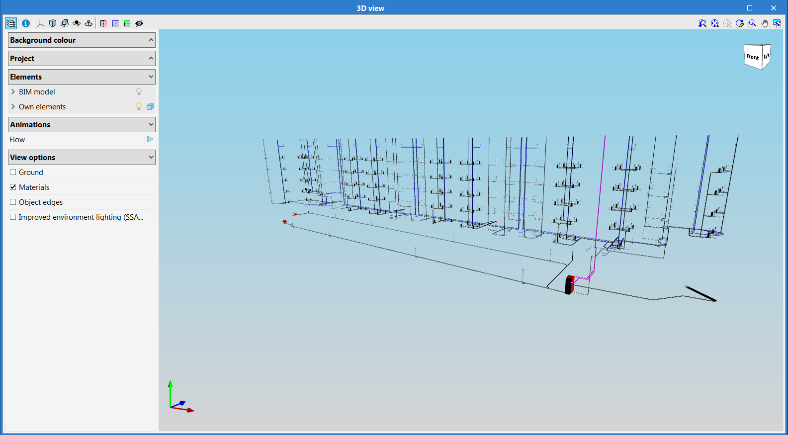
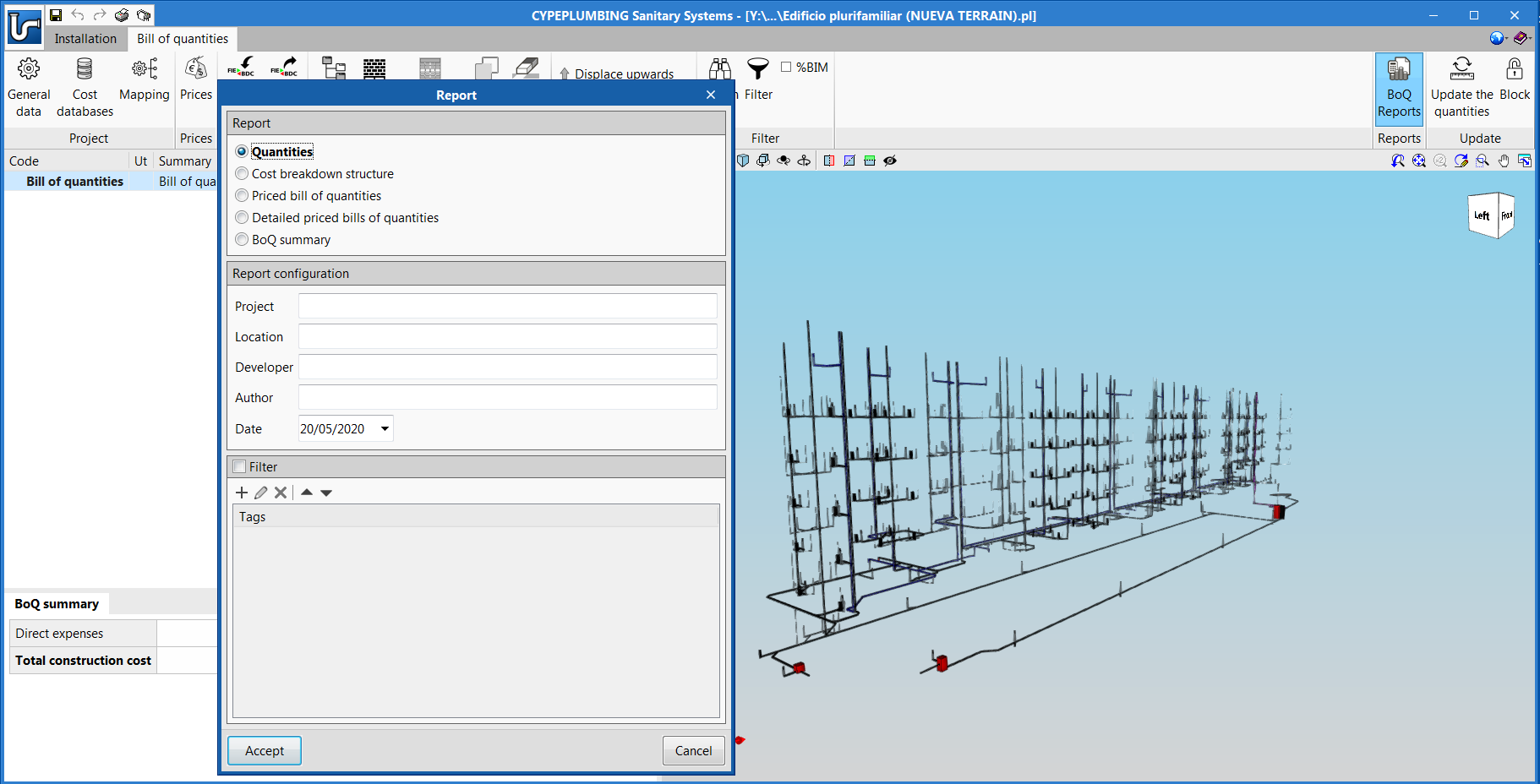
- CYPEPLUMBING Sanitary Systems
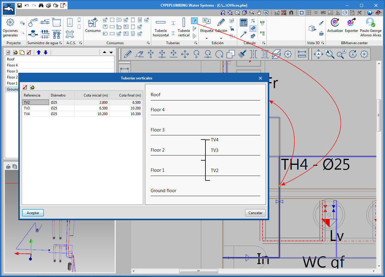
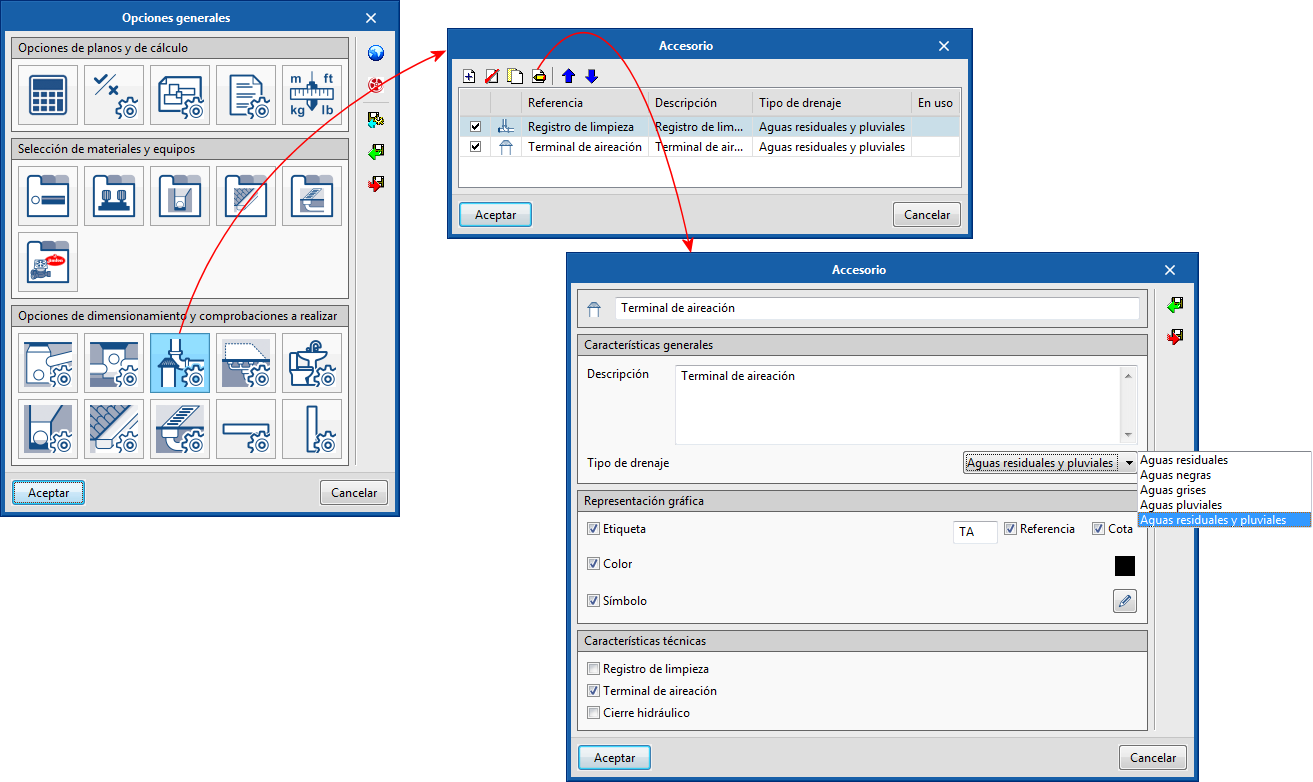
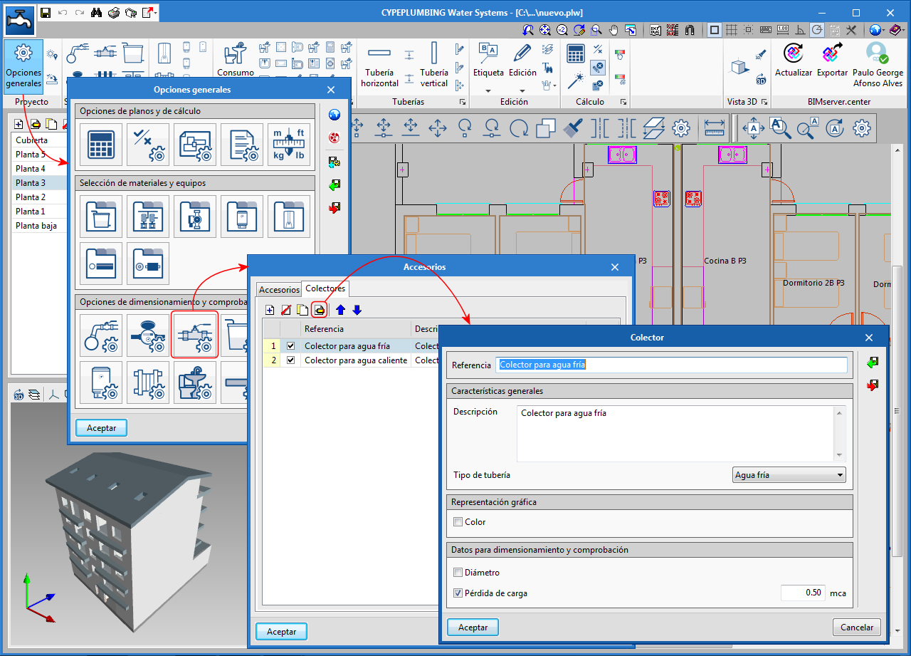
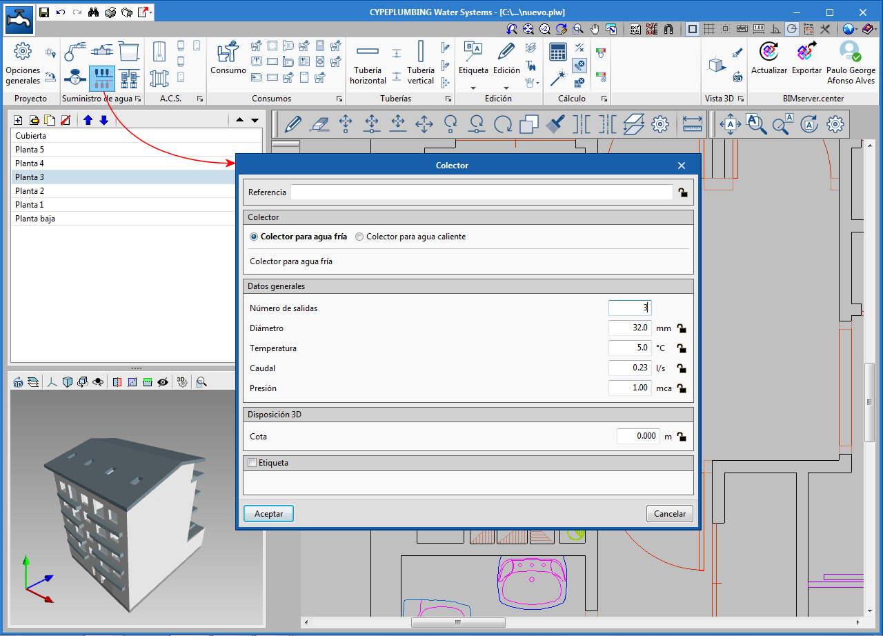
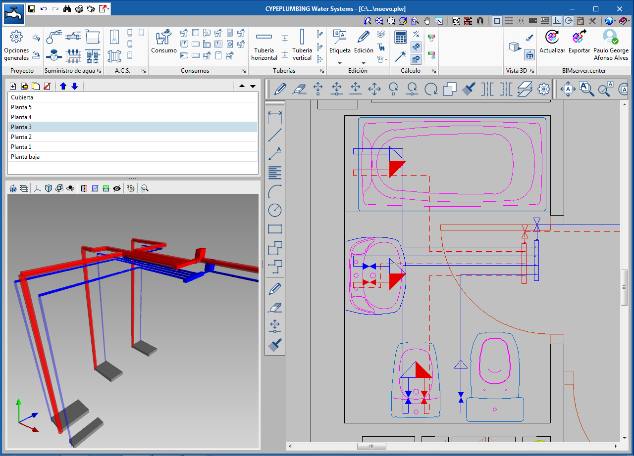
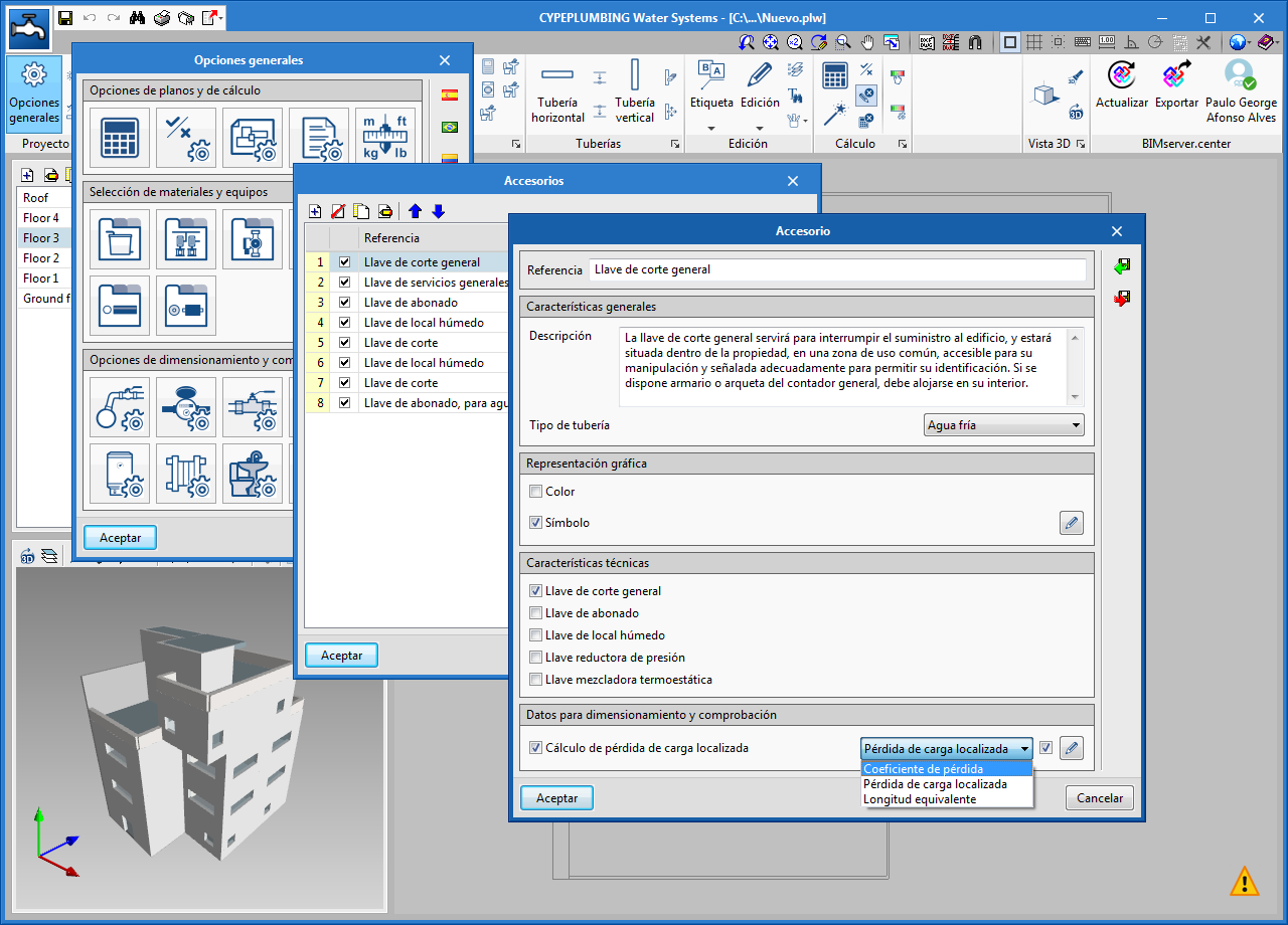
- CYPEPLUMBING Water Systems
- CYPEPLUMBING Solar Systems
- Open BIM Lighting
- CYPELUX
- CYPELUX CTE
- CYPELUX RECS
- CYPELUX HQE
- CYPELUX LEED