CYPETHERM programs with the EnergyPlusTM motor (CYPETHERM HE Plus, CYPETHERM RECS Plus and CYPETHERM EPlus) can import TOSHIBA Multi-split and 1x1 Split equipment from an IFC file that has been generated and included in the BIM model by CYPETHERM HVAC.


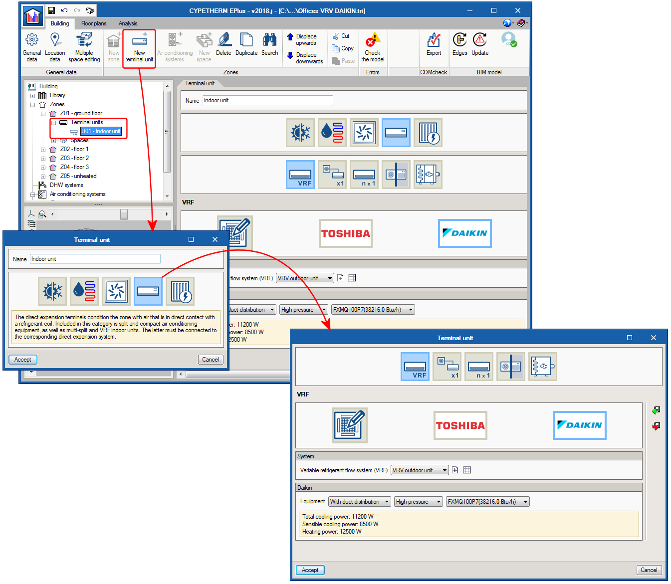
Daikin variable refrigerant volume (VRV) systems
The catalogue of Daikin VRV equipment has been integrated in CYPETHERM programs that have the EnergyPlus™ motor (CYPETHERM HE Plus, CYPETHERM RECS Plus and CYPETHERM EPlus). This way, the number of manufacturers amongst which users can choose variable refrigerant flow (VRF) systems is increased.
The Daikin logo has been added in Direct Expansion Air Conditioning Systems, in the VRF button. By clicking on it, users can choose amongst the different Daikin air-condensed VRV outdoor unit series and models, which are completely defined in the program. Similarly, Daikin indoor VRV units can be added using the New Terminal Unit button, Direct Expansion type, VRF button.
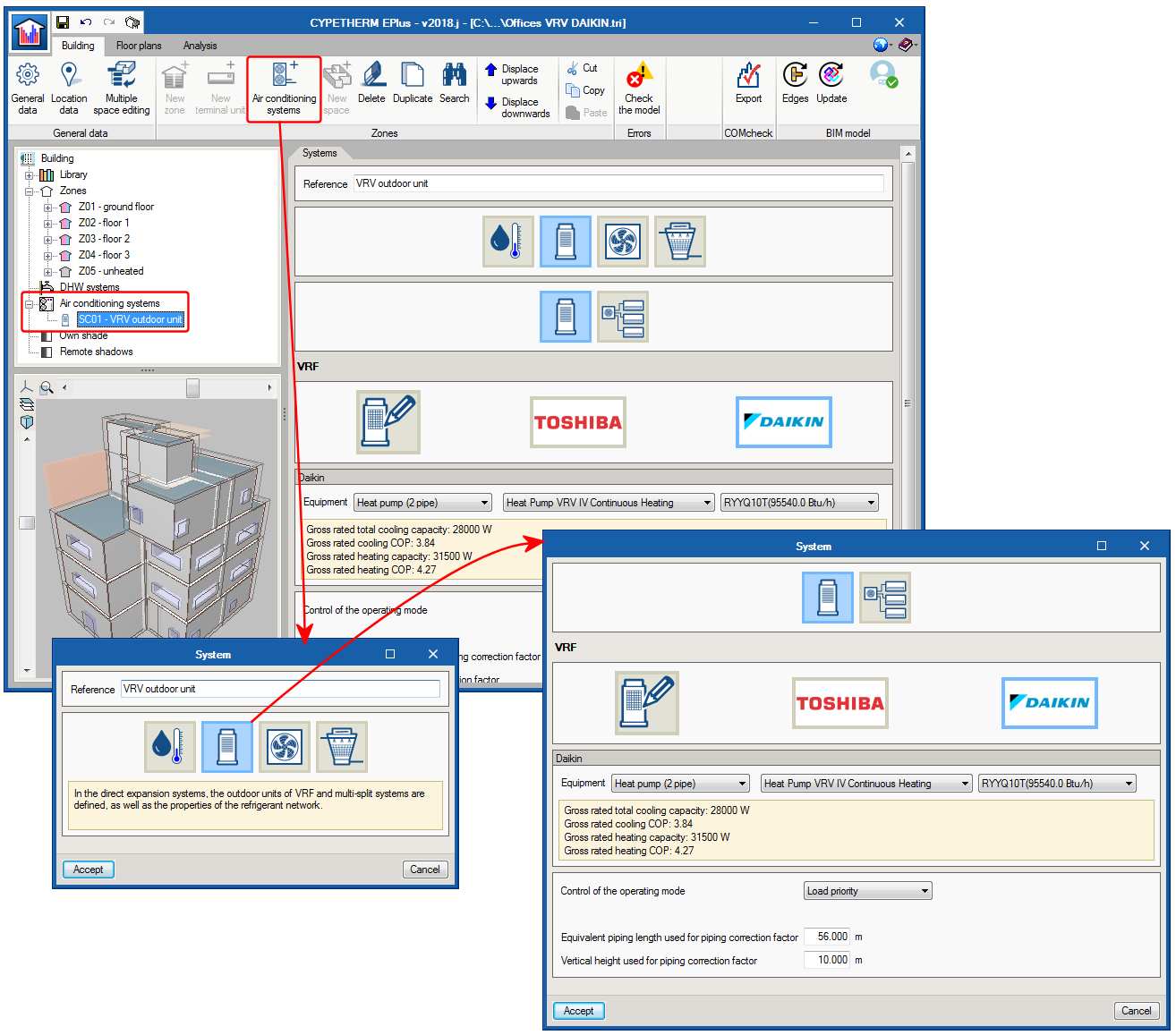
It is not possible to combine indoor and outdoor VRF systems of different manufacturers, nor manufacturer models with generic models.
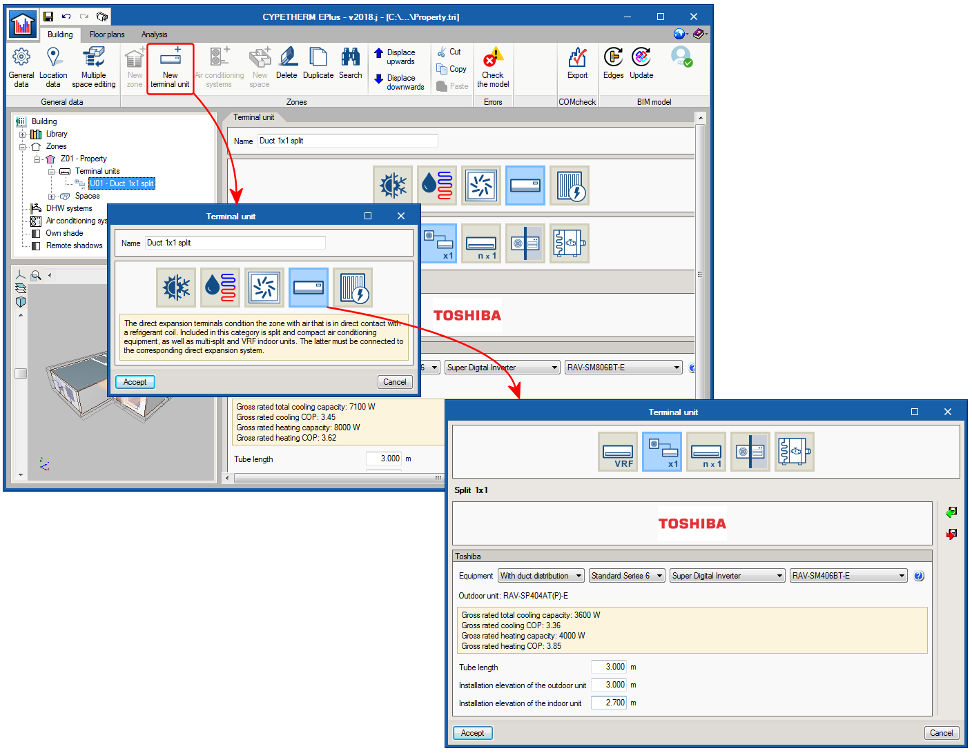
TOSHIBA duct 1x1 split equipment
As of the 2018.j version, TOSHIBA duct 1x1 split equipment can be simulated in the program. As occurs with existing split 1x1 systems (wall and floor), duct systems are defined as terminal units within each zone.
To add TOSHIBA duct 1x1 split equipment, a new terminal unit must be added, then select the “Direct expansion” category, where the Split 1x1 button appears. In the panel that is shown when this button is clicked on, users can choose amongst different TOSHIBA wall and floor duct split models.
When a duct 1x1 split model is chosen, users must define the length of the refrigerant pipe, the installation levels of the outdoor and indoor units. These parameters are used to calculate the associated power loss.
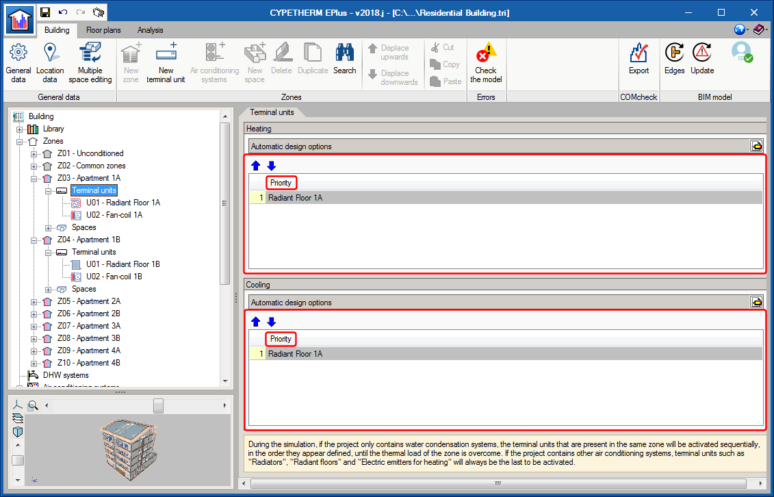
Definition of the activation sequence of terminal units
During the energy simulation carried out by CYPETHERM programs with the EnergyPlusTM analysis motor, air-conditioning terminal units defined in each thermal zone are activated sequentially until the thermal load of the zone is overcome. In previous versions of these programs, the order of the activation sequence was that in which the terminal units appear in the diagram.
As of the 2018.i version, the activation sequence of the terminal units of each zone is defined in their own panel, within Terminal units, and the program distinguishes between air-conditioning and heating.
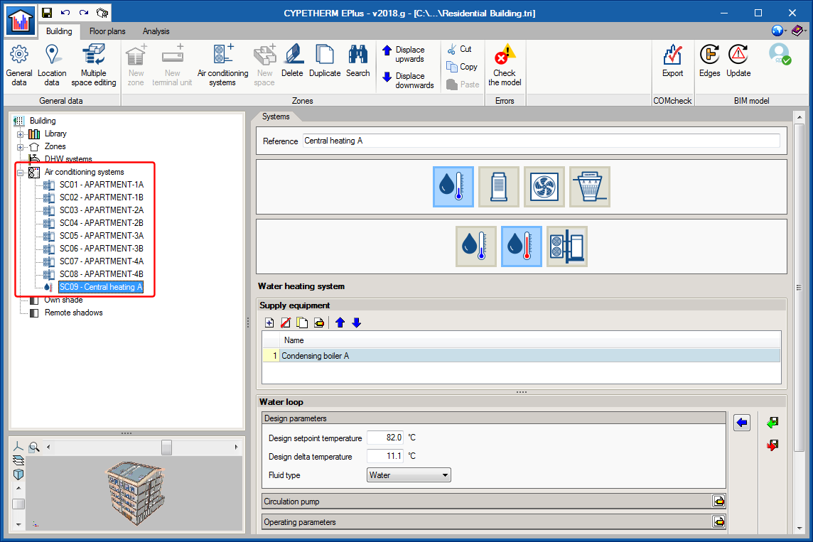
Definition of multiple water air conditioning systems in the same project
As of the 2018.g version of CYPETHERM programs with the EnergyPlus analysis engine, users can define more than one water-cooling and/or heating system in the same project, as long as other types of air conditioning systems are not defined. If other types of air conditioning systems are defined, as occurred in previous versions, only one type of water-air conditioning system can be defined of each of these types (cooling and heating) for all the building.
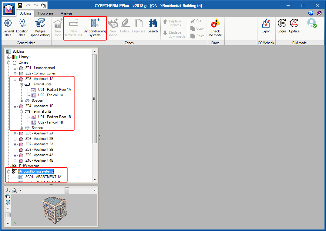
New interface for the definition of air conditioning systems
As of the 2018.g version, CYPETHERM programs with the EnergyPlus analysis engine contain a new, more functional and intuitive interface to define air conditioning systems.
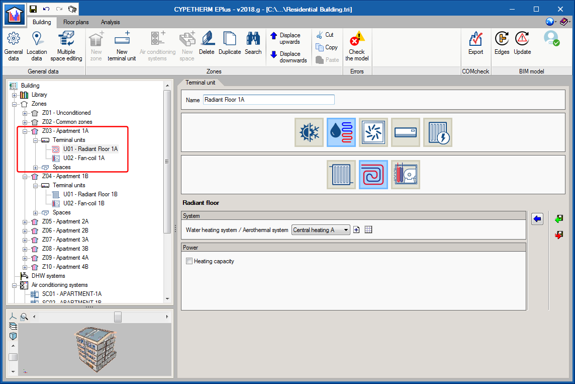
In CYPETHERM EPlus, HE Plus and RECSPlus, the air conditioning installation is divided into Terminal units and Air conditioning systems. Until now, both parts were defined in the same general panel. This panel has been removed and as of the 2018.g version, terminal units are defined within each thermal zone, whilst air conditioning systems are defined in their own section. Now, the terminal units and air conditioning systems created by users are added as elements in the tree diagram located in the top left of the screen, and therefore all the options and editing methods that are used for the elements of the tree are applicable.
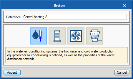
To create an air conditioning system, the new Air conditioning systems button is used. The air conditioning systems available in previous versions have been renamed and classed by type. Hence, in the first window of the assistant, users can choose following the buttons from left to right, amongst:
- Water-air conditioning systems
Located here are water heating and cooling systems and aerothermal systems. - Direct expansion systems
Variable refrigerant flow (VRF) and multi-split outdoor units can be defined here. - Air-air conditioning systems
Users must first choose the type of system (constant or variable air volume, simple or double duct) and then the type of air conditioner. - Water condensation systems
The water circuits for coolers are defined here (these circuits were previously defined together with the cooling by water circuit) as are heat pumps.
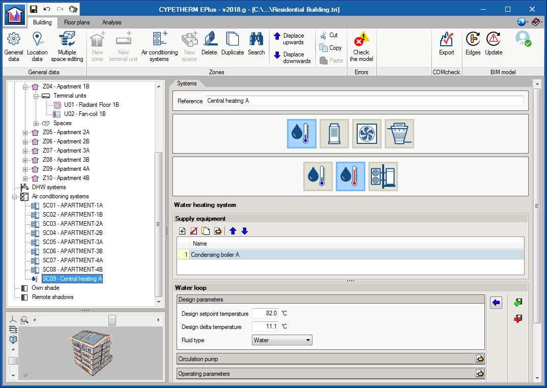
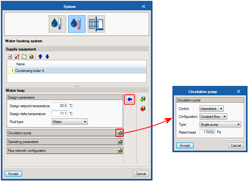
In the second window of the assistant, the properties of the chosen system are defined. To help users to introduce the data, the properties that can be edited have been grouped depending on the part of the system to which they refer and the texts have been revised. The panel only displays the basic properties of the system users are to define, whilst the variable that configure the details of the system are displayed by clicking on the “Edit” button located to the right of each section. Additionally, the “Default values” button has been added, which allows users to recover the values that were proposed by the program.
By clicking on “Accept”, the air conditioning system that has been created with the assistant is added to the tree diagram, within the Air conditioning systems section. Upon selecting it, its edit panel opens, where users can edit all the properties defined using the assistant.
The project can be analysed when there are air conditioning systems defined in the tree that are not connected to any terminal unit. This way, users can have systems saved in the project that do not affect the simulation.
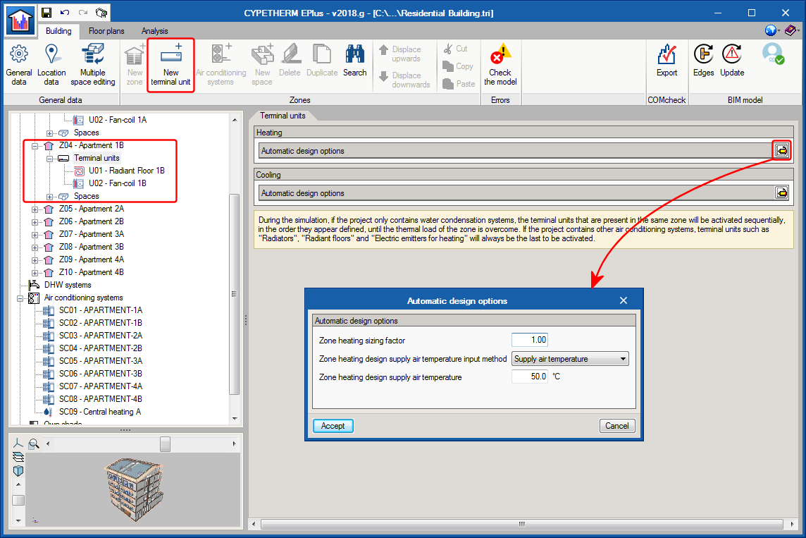
The terminal units are located in each zone. When the “Terminal units” section is clicked on in the tree diagram, the panel in which users can edit the options EnergyPlus™ uses to automatically design the air conditioning equipment that sees to each zone. Users are informed of the priority order with which the different units that are defined in the same zone are simulated.
To add a new terminal unit, the “New terminal unit” is used, which opens an assistant that is similar to that of the Air Conditioning Systems. The terminal units have also been renamed and classed by type, which helps to identify the system to which they can be connected. In the first window of the assistant, following the buttons from left to right, users can choose amongst:
- Constant performance equipment
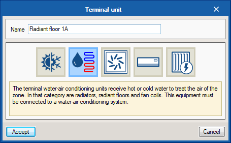
- Terminal unit for air conditioning by water
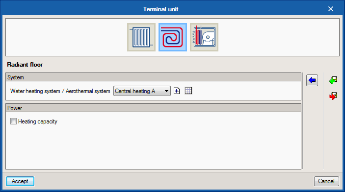
Located here are radiators, radiant floors and fan coils. In this category, that which was previously known as “Radiant heating terminal” has been divided into “Radiator” and “Radiant floor”, with the aim to help users identify this equipment more easily. - Terminal unit for air conditioning by air
Users can choose amongst various air discharge terminals corresponding to different types of air-air conditioning systems. - Direct expansion terminal unit
Autonomous air conditioning equipment is defined here (compact, 1x1 split, water-air heat pump) and indoor direct expansion systems. - Electrical emitter for heating
In the second window of the assistant, the specific equipment is selected and its properties are defined. Most terminal units have to be connected to an air conditioning system. In the “System” section of this window, the systems that are compatible with the chosen terminal unit are indicated. As in previous versions, the terminal unit must be connected to a system to be able to create it. If a compatible air conditioning system already exists in the project, it will be displayed in the drop-down options. If there are no compatible systems, users may create one from the terminal unit panel, or edit an existing one.
By clicking on “Accept”, the terminal unit that has been created with the assistant is added to the tree. When it is selected, its edit panel opens, where users can edit all the properties that were defined using the assistant.
Definition of the demand of the total domestic hot water of the building
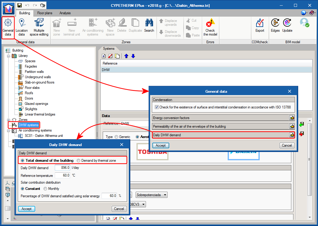
Users can now define a single domestic hot water demand for the whole building. Until now, the domestic hot water demand was defined for each thermal zone. Users can choose between both options in the Building tab > General data > Daily DHW demand.
If the “Total demand of the building” option is chosen, only one system will be defined within “DHW systems”, which will be that seeing to the total demand of domestic hot water.
DAIKIN Altherma aerothermal systems
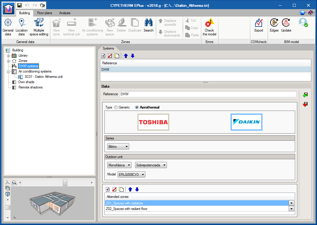
The catalogue of Altherma aerothermal systems from DAIKIN has been incorporated. The DAIKIN logo can be seen in the aerothermal water-air conditioning systems category. In the panel that opens when clicking on the logo, users can choose amongst the three Altherma series equipment: Monobloc, Bibloc and HT.
Depending on the series that has been chosen, in the panel, users can choose amongst the different indoor and outdoor models of DAIKIN Altherma systems choose whether the system will only be used for heating or also for cooling. Additionally, users must specify the working temperature conditions of the installation and its mode of operation during the year.
DAIKIN Altherma equipment has also been incorporated in the domestic hot water systems panel.

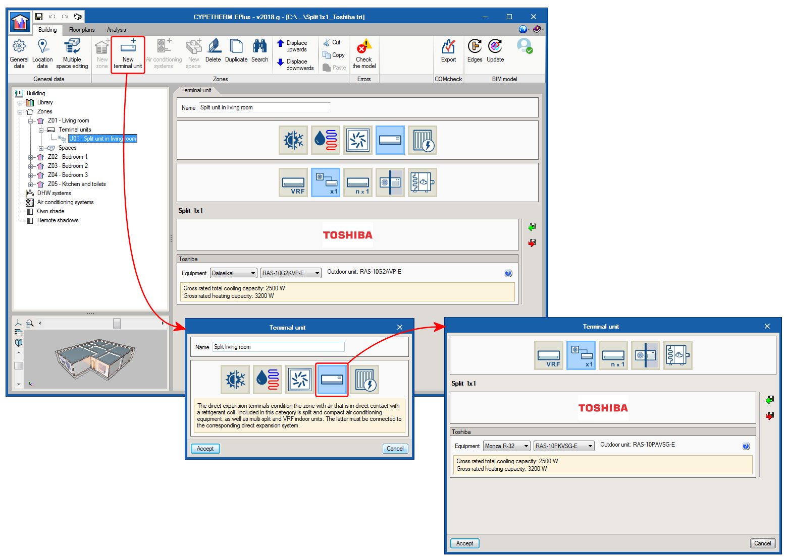
TOSHIBA 1x1 split equipment
As of the 2018.g version users can simulate TOSHIBA 1x1 split floor and ground equipment. This equipment is defined as terminal units in each zone.
To add a TOSHIBA 1x1 split, a new terminal unit must be added and select the direct expansion category where the 1x1 split button appears. In the panel that opens upon pressing this button, users can choose amongst the various TOSHIBA wall and ground split models.
Several indoor 1x1 split-type units can be defined in the same thermal zone. In the simulation, EnergyPlus will sequentially use the terminal units that are located in the same zone, in the order they have been defined.
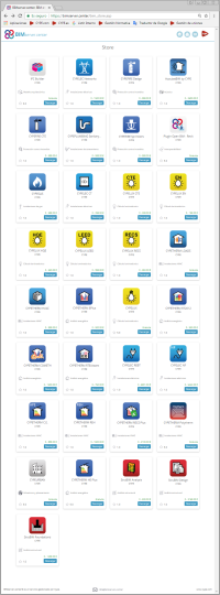
Program downloads on the BIMserver.center platform
The following CYPE programs are available to be downloaded from the BIMserver.center platform:
- CYPELUX CTE
- CYPELUX EN
- CYPELUX HQE
- CYPELUX LEED
- CYPELUX RECS
- CYPETHERM EPlus
- CYPETHERM RT2012
- CYPETHERM COMETH
- CYPETHERM REH
- CYPETHERM RTExistant
- CYPETHERM RECS Plus
- CYPETHERM C.E.
- CYPETHERM LOADS
- CYPETHERM HVAC
- CYPELEC REBT
- CYPELEC NF
- CYPELEC CT
These programs are also available on the main CYPE program menu, which is installed with the file that can be downloaded from the Download Area of the CYPE website.
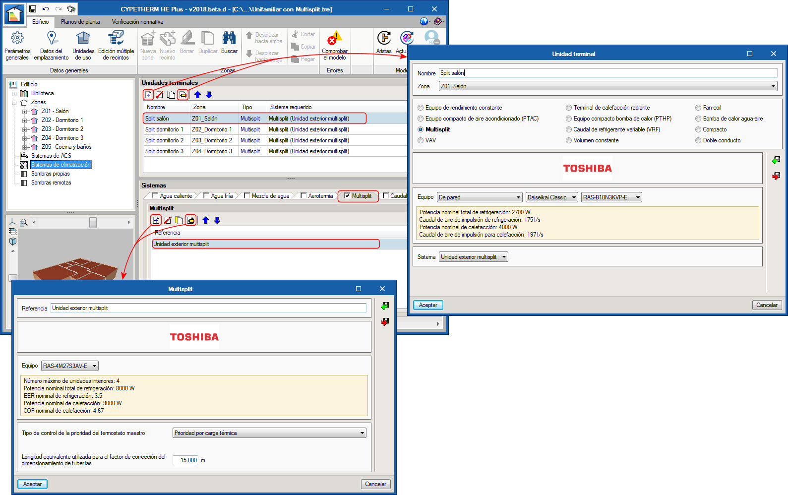
TOSHIBA multi-split systems
As of the 2018.d version, it is possible to define TOSHIBA multi-split systems. These systems consist of an outdoor unit and between 2 and 5 indoor units.
In Air conditioning systems, the new tab: Multisplit appears, where users can add and define outdoor units of this type contained in the project. In the panel, users can choose amongst different outdoor TOSHIBA multi-split units and define some conditions of the installation which are required for the design process.
Indoor multi-split units are defined in the Terminal units section, where the new type of terminal unit: “Multi-split”, has been included. In this panel, users can choose amongst TOSHIBA models and must indicate which outdoor unit is connected to the indoor unit that has been defined.
It is possible to define several multi-split type indoor units within the same thermal zone. In the simulation, EnergyPlus™ will sequentially use the terminal units that are located within the same zone and following the order defined in the Terminal units list.