Update history​

CYPETHERM HVAC

Thermal zones

The concept “thermal zone” has been introduced. A thermal zone is a group of spaces with a simultaneous thermal zone, which is used to define the power required in the production equipment.

Thermal zones could already be defined in CYPETHERM LOADS. As of the 2018.a version CYPETHERM HVAC can import them and assign them the load required in an Aerothermal system.

TOSHIBA Multi-Split Systems

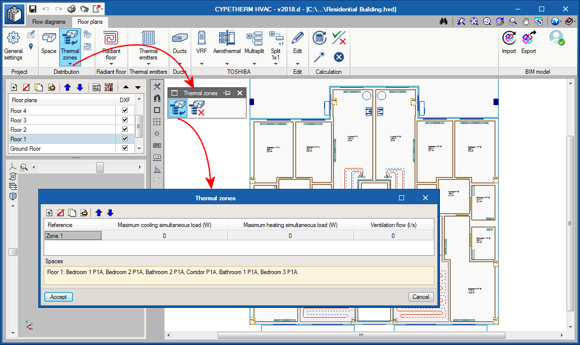
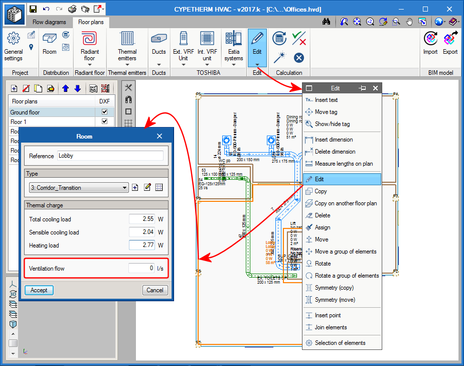
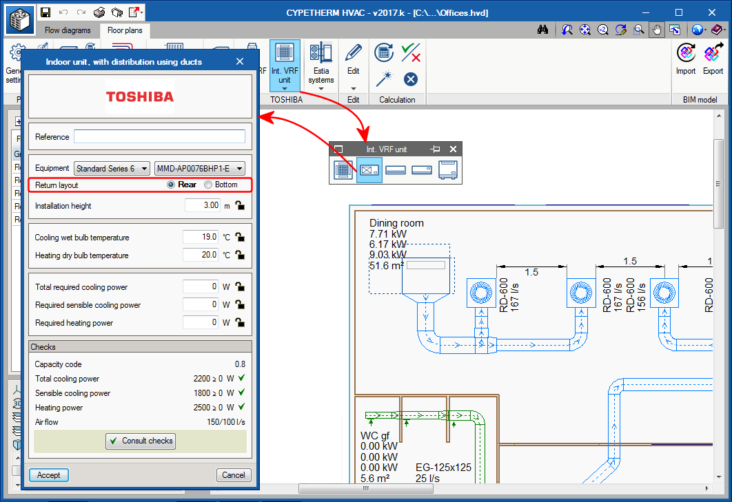
As of the 2018.a version, it is possible to define TOSHIBA multi-split systems. These systems consist of an outdoor unit and between 2 and 5 indoor units.

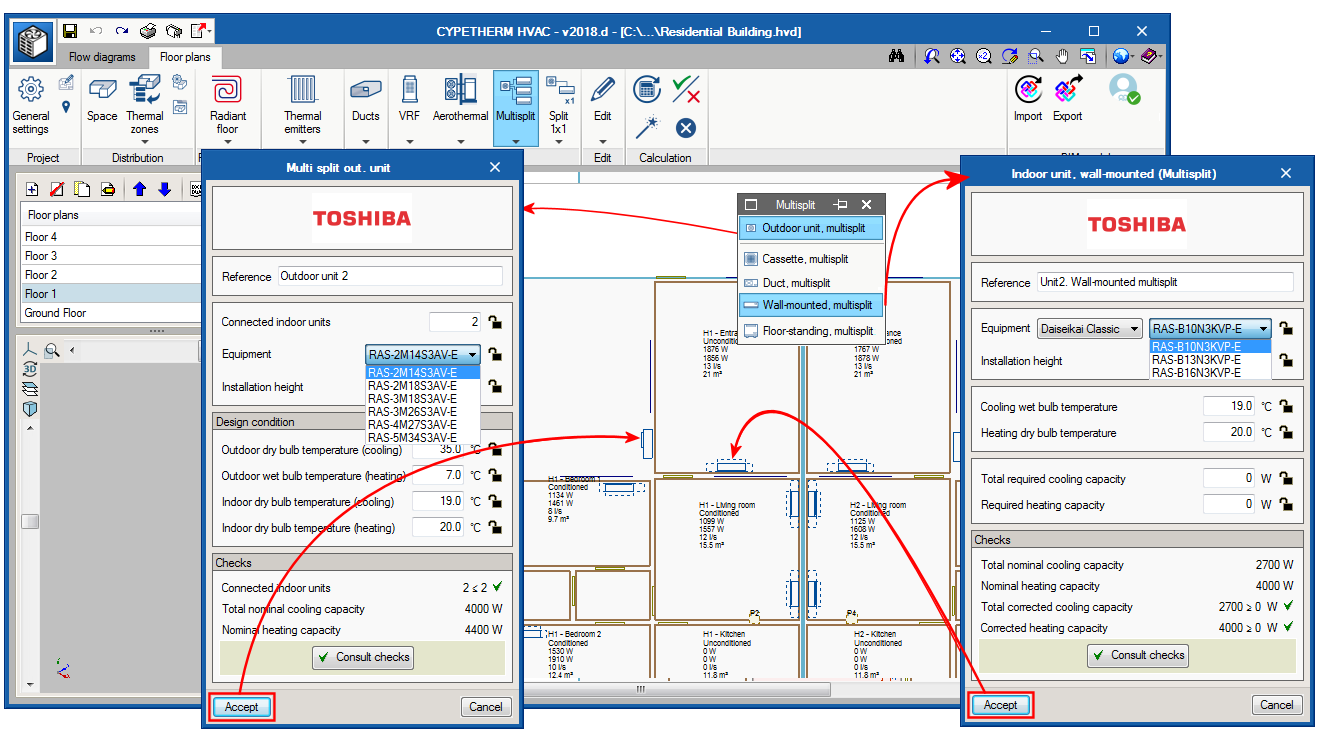
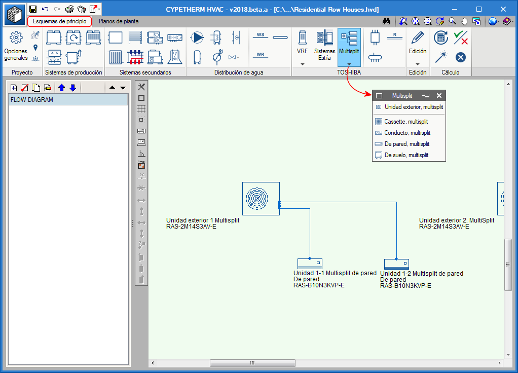
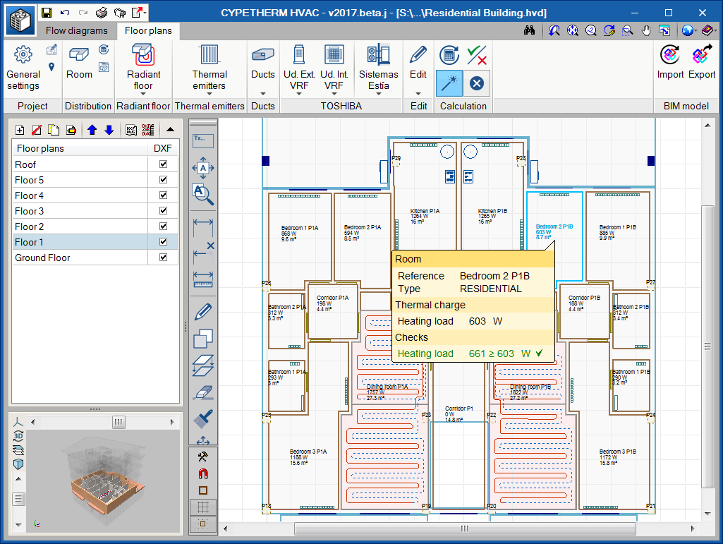
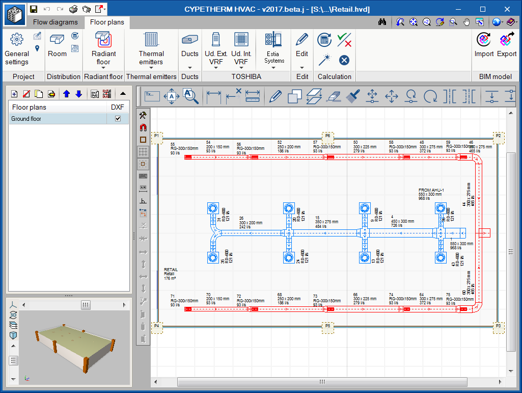
The design process is as follows: users place the indoor units (cassette, duct, wall or floor units) in the spaces, and the outdoor unit on the façade or roof of the building. They are joined using refrigerant pipes in the Flow diagrams tab.

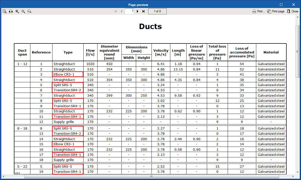
Upon designing, the program automatically selects the indoor and outdoor models, as well as the diameter of the pipes. Regarding the results, the program generates, as well as the drawings, a design report of the system and the quantities of the elements provided in the installation.

Between 2 and 5 indoor units can be connected to the outdoor units that have been provided.

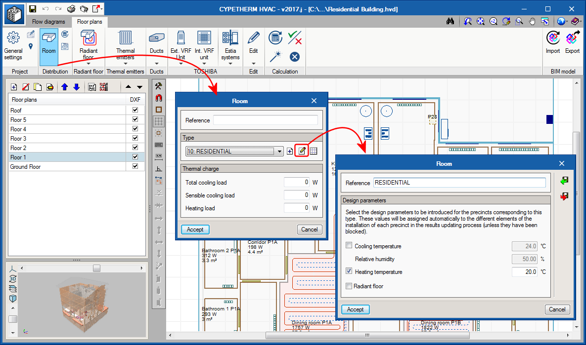
For CYPETHERM HVAC to be able to design a TOSHIBA Multi-split system, the user license must contain the “Direct expansion systems” permission.

TOSHIBA multi split systems (CYPETHERM HVAC module)

The 2018.a version allows users to design TOSHIBA multi split systems with outdoor units to which 2 to 5 indoor unit can be connected.

More information on the inclusion of these air conditioning systems can be found in TOSHIBA multi split systems.

Contextual menu of the installation elements

When the right mouse button is pressed when the cursor is positioned over an element of the installation, or over the limits of a room, a contextual menu appears containing options to edit or delete the selected element, or consult results when applicable (e.g. of ducts).

Radiant floor

Bill of quantities for Polytherm products

The 2017.k version of CYPETHERM HVAC and CYPETHERM Polytherm contain the bill of quantities which includes the Polytherm products used in the design of the installation. This way, as well as the program providing a complete report of the results of the installation designed with Polytherm, the programs incorporate a detailed bill of quantities of the Polytherm radiant floor, with images, descriptions, prices and quantities of all the products.

Radiant floor path editing tools

As of the 2017.k version, CYPETHERM HVAC and CYPETHERM Polytherm incorporate a new tool to edit radiant floor circuits, which users can use to modify the paths that are generated automatically by the program.

Ventilation flow rates

The 2017.k version includes the “Ventilation flow” for each room. As occurs with loads, this data can come from the BIM connection with CYPETHERM LOADS or defined manually in the program by users.

Information on Toshiba Estia and VRF systems on floor plans

The “Cooling systems” button has been included in the “Drawing settings” dialogue box, which allows users to activate the reference, type and model of the indoor and outdoor VRF system units and TOSHIBA Estia units, to then display this information on floor plans.

ASHRAE reference for duct fittings

Fittings (elbows, transitions and splits) appear in the duct lists (“Type” column) with their ASHRAE reference. This data allows for the element to be identified more clearly.

Connection of indoor VRF units with duct distribution

Air discharge

When a discharge grille is introduced (Ducts > Straight duct), a snap point appears on the indoor VRF units with duct distributions on the current floor.

This point is the starting point of the discharge duct that joins the indoor unit with the rooms it provides air to. This way, the program automatically distributes the loads of those rooms and the air flow moved by the unit, between the grilles and diffusers of the discharge duct.

  • Load distribution
    When the project is analysed, the thermal loads of the rooms connected to the indoor unit with the discharge grille are transferred to the indoor machine. The program takes into account the following configurations:
    • Several machines providing air to the same room
      The program will distribute the load equally for each machine.
    • One machine providing air to several rooms
      The load assigned to the machine will be the sum of all the rooms.
    • There is another system in the room
      If another system exists in the room to which the VRF unit provides air, e.g. a radiator, the load assigned to the machine will be the remaining load (the room load minus the radiator load), as long as the “Simultaneous” option has been selected in “General settings > Distribution of the thermal load of the precincts amongst the systems”.


  • Air flow distribution
    When the air flow that is moved by the machine is calculated, it is shared amongst the grilles and diffusors of the discharge duct. The program takes different configurations into account:
    • One machine that provides air to several diffusors and grilles in the room
      In this case, the program will divide the flow between them. If users set the flow of a grille or diffuser at a specific value, the remaining flow moved by the machine will be shared amongst the grilles and diffusors that do not have a set flow value.
    • One machine that provides air to several rooms
      This is the usual case in dwellings. The discharge flow is shared amongst the discharge duct grilles depending on the cooling load of each room.

Air return

The configuration of the return position is defined directly in the panel of the indoor unit. There are two possible return positions:

  • Rear
    In this case a return duct network will have to be provided.
  • Bottom
    It will be placed opening to a grille in the false ceiling without a return duct network.

Dimensions and measuring tools

Three new tools have been included for measuring and dimensioning in the “Floor plans” tab:

  • New dimension
  • Delete dimension
  • Measure lengths on plan

Design temperature of rooms and check

The design temperature for heating and cooling is defined for types of rooms. By unmarking the heating or cooling “check”, the heating or cooling load for that room will not be checked.

This case is represented in the “Residential Building ” example that is installed with the program. Aerothermal equipment with radiators and radiant floors to only cover heating loads, have been included in the building of this example. Therefore the cooling check is unmarked and no warnings will be displayed.

Duct fittings

Two new ASHRAE discharge fittings have been added, for cross-shaped branches: a round duct with code SD5-24 and a rectangular duct with code SR5-21.