Update history​

Continuous beams

Reinforcement tables. Admissible diameters depending on the depth of the beam

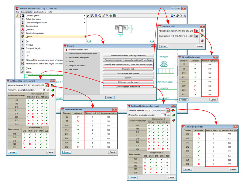
The admissible diameters contained the reinforcement tables for transverse reinforcement, top additional reinforcement and bottom additional reinforcement, can be deactivated depending on the depth of the beam.

The top additional reinforcement and bottom additional reinforcement tables include two new columns: Minimum depth and Maximum depth, which allow users to define a beam depth interval for each admissible diameter, so that if the depth lies outside this range, the diameter is not used. The transverse reinforcement tables only contain one new column, Maximum depth, which allows user to deactivate the admissible diameters for beams exceeding that value.

These improvements have also been implemented in CYPECAD.

New features in Continuous Beams. New tools for Reinforcement edition

New beam edition tools have been implemented in the beam editor (  button) in the 2013.e version of Continuous beams. These improvements also appear in CYPECAD’s new beam editor, as it is the same editor as for Continuous beams. These tools are described below:

Join longitudinal reinforcement

The option: Join reinforcement, has been implemented in the Longitudinal reinforcement dialogue box (  button), allowing users to join reinforcement bar packs of the same diameter. Users select two bar packs and indicate the amount of bars of these packs which are to be joined.

Change of stirrup type in the same span

A new option: Transverse reinforcement arrangement, has been implemented in the transverse reinforcement edition dialogue box (  button > Edit reinforcement). Two options are available in this section:

  • The same as for assembly reinforcement
    Assigns the transverse assembly reinforcement to the selected stirrup span.
  • Specific for this interval
    Users can assign a different reinforcement type to that of the assembly reinforcement, to the selected stirrup span.

Grouped stirrups

Two fields have been implemented in the transverse reinforcement edition dialogue box (  button > Edit reinforcement), where users can indicate the number of grouped stirrups or grouped bars (if the stirrup type contains bars)

Transverse sections defined by users

Using the new Transverse sections dialogue box (  button), users can configure the sections of the frame which are to be displayed with the following options:

  • Generate transverse sections
  • Introduce a transverse section defined by a single point
  • Introduce a transverse section defined by two points
  • Delete a transverse section

Beam options

The 2013.c version includes more design and check options for concrete beams, and for representation in drawings and takeoff for steel beams. The options of Continuous beams can be edited in Job data > Options. All the available options can be consulted in this dialogue box. The options which have been implemented in the 2013.c version are:

  • Design / Code checks
    • Assembly reinforcement
      The program considers the following construction arrangements:
      • Stirrup-carrying reinforcement
      • Continuous assembly reinforcement in the span
    • Top reinforcement
    • Bottom reinforcement
    • Transverse reinforcement
      • Stirrup symmetry
      • Tie all the longitudinal bars
        This option allows for all the longitudinal bars to be tied using crossties even if they are provided in different layers. It is of great use for countries where this is commonly used in their construction methods (France, Morocco or Algeria).
      • Stirrups of different diameter in a beam
      • Multiple stirrup layout
    • Stirrup-carrying reinforcement
      The transverse reinforcement layout is configured in this section for when stirrup-carrying assembly reinforcement construction layout is used (can be selected in the Assembly reinforcement option). There are different configurations for:
      • Rectangular sections
      • Rectangular sections with one flange
      • Rectangular sections with two flanges
  • Steel beams
    • Length to consider in steel beams
      The length to consider for steel beams in beam drawings and in their takeoff is indicated in this section:
      • Up to the face of the support element
      • Up to the axis of the support element
      • Up to the axis in intermediate supports and the external face in end supports

Reinforcement area graphs

Implemented in Continuous beams are graphs representing the required area of the reinforcement and the effective area of the reinforcement provided in a frame.

These graphs are represented in the reinforcement edition screen (Job data > Reinforcement edition and results consultation of the selected frame). Displayed in the top part of the screen is the reinforcement of the frame (where the force diagrams can be represented) and in the bottom part are the area graphs.

Users can select the longitudinal reinforcement area representation (top and bottom) or that of the transverse reinforcement area. The area required depending on the resistance and minimum required reinforcement can be represented in each representation (longitudinal or transverse) or just the area required depending on the resistance. The numerical values of the areas can also be viewed. These representation options can be configured in the Reinforcement area graphs section, located in the left side menu of the reinforcement edition screen.

The reinforcement area graphs are of great use for when introducing or modifying the reinforcement. Users can see the areas covered by the reinforcement whilst the introduction or modification is taking place (even deducting its anchorage length).

Code implementation in the continuous beams program

Concrete

  • ABNT NBR 6118:2007 (Brazil)
    Norma Brasileira ABNT NBR 6118 (2007). Projeto de estruturas de concreto - Procedimento.

    Implemented in Continuous beams (as of the 2013.a version). The program only checks the reinforcement provided by the user for this code. The design of the reinforced concrete sections in accordance with NBR 6118:2007 will be available in upcoming versions.
  • IS 456: 2000 (India)
    Indian Standard. Plain and reinforced concrete code of practice (Fourth Revision).

Rolled steel, welded steel and cold-formed steel codes

  • ABNT NBR 8800:2008 (Brasil) (Rolled steel and welded steel)
    Norma Brasileira ABNT NBR 8800 (2008). Projeto e execução de estruturas de aço e de estruturas mistas aço-concreto de edifícios - Procedimento.
  • ABNT NBR 14762:2010 (Brazil) (cold-formed steel)
    Norma Brasileira ABNT NBR 14762 (2010). Dimensionamento de estruturas de aço constituídas por perfis formados a frio - Procedimento.
  • NTC: 14-01-2008 (Italy)
    Norme tecniche per le costruzioni.
  • IS 800: 2007 (India)
    Indian Standard. General construction in steel - Code of practice (Third Revision).