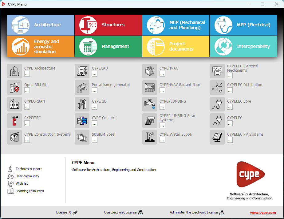
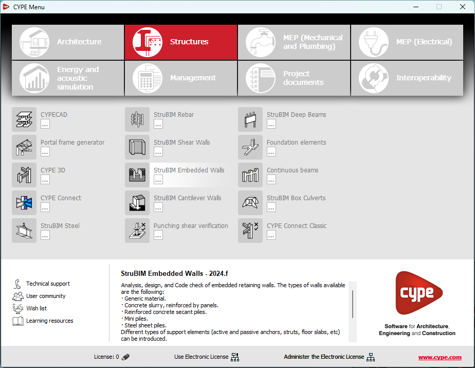
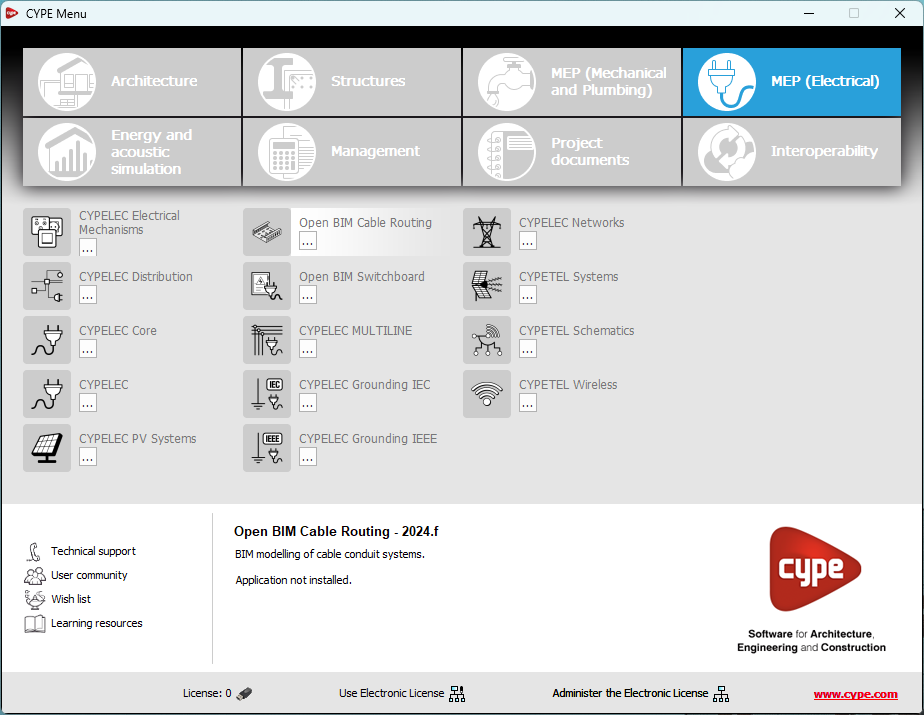
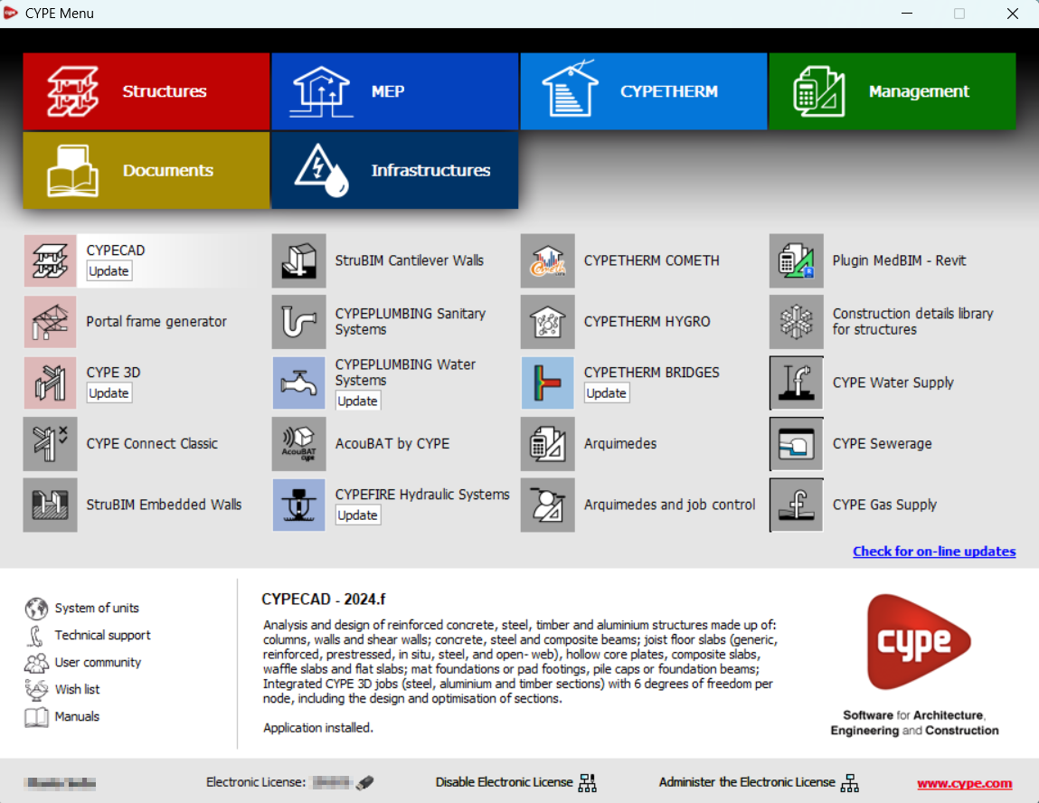
Most of the CYPE applications are sorted into these groups. In previous versions, most of these applications could only be downloaded as single applications from the BIMserver.center platform.
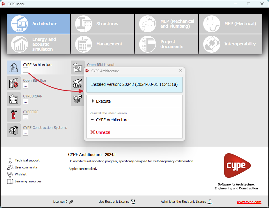
By downloading and installing CYPE Menu, users will only have the CYPE programs menu installed, but none of the applications included in it will be downloaded or installed. Initially, each of the icons representing the CYPE Menu applications appears in a box with a grey background. When clicking on any of them for the first time (or on the button under the application's name), a contextual menu will appear allowing users to download and install the latest version of that application or an earlier version if available. Earlier versions (from 2024 onwards) will be available for those programs that include paid modules. Normally, free applications will only allow the latest version of these programs to be installed. Any installed version of any application can be uninstalled.
When an application has been installed, by clicking on the button under its name, the context menu that appears includes the "Uninstall" option.
As of version 2025.a, the CYPE program menu can only be downloaded from the BIMserver.center platform.
The CYPE Menu application was already available from version 2024.b on the BIMserver.center platform. Now, in version 2025.a, the advantages of CYPE Menu compared to previous versions, which were downloaded from the download area of the CYPE website, are as follows:
CYPE Menu allows users to manage the updates of the applications it contains.
As of version 2025.a
New program groups and many CYPE applications that could only be downloaded directly from BIMserver.center are included.
The version of each application to be installed can be selected (from version 2024 onwards).
Previously installed applications can be uninstalled.
Further information on the new features can be found in the following new features of CYPE Menu version 2025.a.
In the download area of the CYPE website, the download of the program menu for versions prior to 2025.a (in 64-bit and 32-bit) will still be available. In this download area, there is also a link to the BIMserver.center platform "Store" for downloading the 2025.a version of "CYPE Menu".
As a result of these changes, the 32-bit version of the CYPE Menu is no longer available in version 2025.a. As of 18 February 2019 (version 2019.f), the CYPE programs have been running on 64-bit systems. Since then, only the classic CYPE menu could be installed on 32-bit systems. All other applications (downloadable from the BIMserver.center platform) only worked on 64-bit systems. We believe that 32-bit programming is no longer feasible to take advantage of the superior performance of 64-bit processors and operating systems. Users who still want to use certain 32-bit CYPE programs (those available in the "CYPE Menu" prior to version 2025.a) must install a version prior to 2025.a from the download area of the CYPE website, but will not be able to upgrade their programs to later versions. Please refer to our FAQ question "Which version should I download, 64-bit or 32-bit?" for more information on the 32-bit and 64-bit versions.
As of version 2024.f, the CYPE Menu tool (available on the BIMserver.centre platform Store) allows users to manage the updates of the applications it includes.
When accessing the CYPE Menu, the program checks whether there is a newer version of the installed applications and, if so, the "Update" option appears next to them.
The update process will download the application and, once completed, will start the installation.
Calculation of the differed deflection of concrete beams
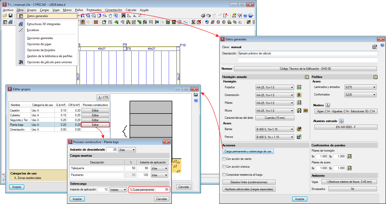
As of the 2019.d version, CYPECAD, CYPE 3D and Continuous beams allow users to edit the percentage of live load to be considered as quasi-permanent load to take it into account when calculating the differed deflection. To do so, the “Construction process” panel has been included in the “% Quasi-permanent” field.
The panel can be accessed as follows:
CYPECAD In CYPECAD, users can indicate a different live load percentage as quasi-permanent load for each floor group:
Project > General data > Permanent and live load > “Edit” button of the floor in question.
CYPE 3D Project > General data > Construction process
Vigas continuas General data > Construction process
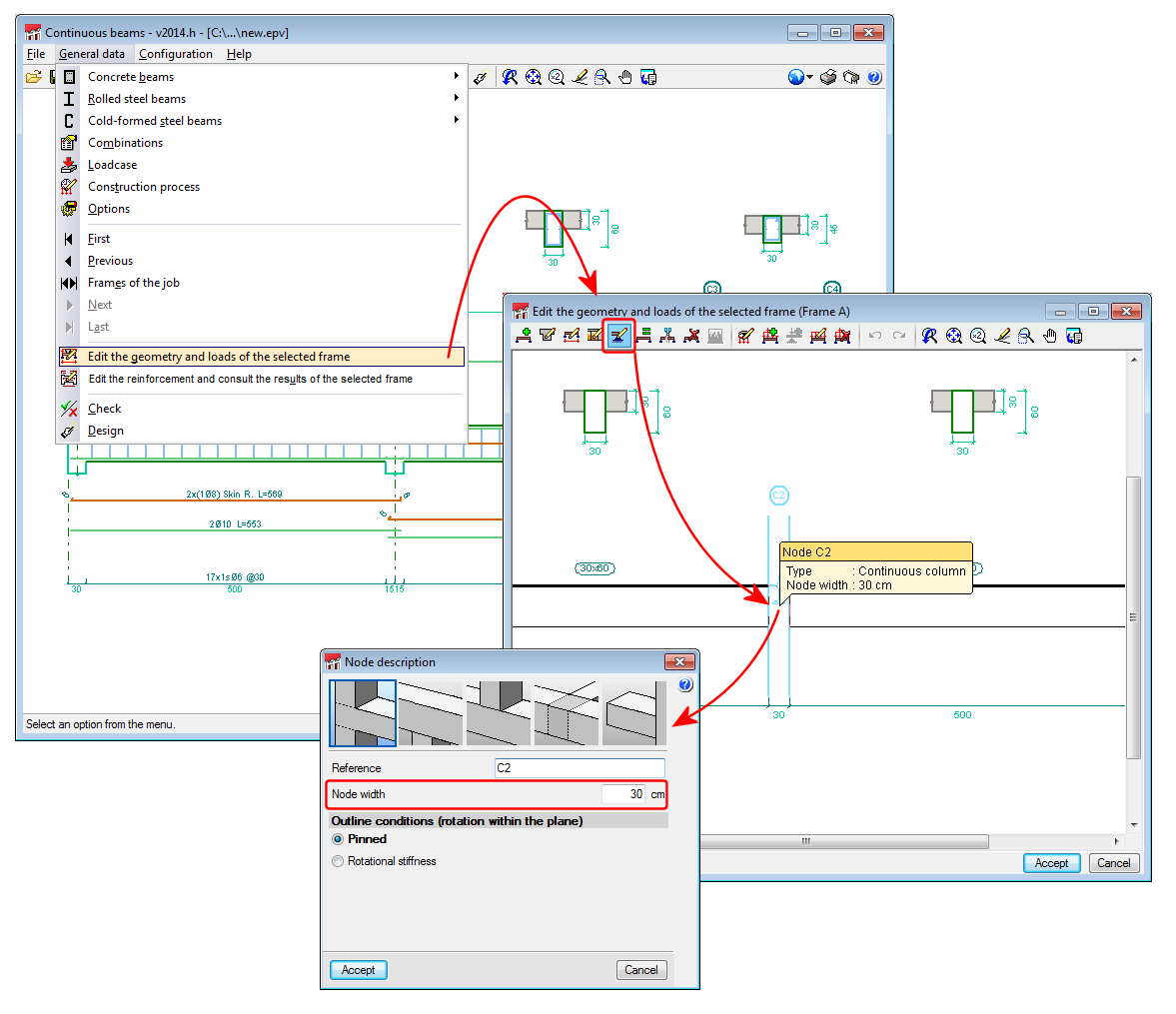
The node width range has been increased to 1000cm (General data > Edit the geometry and loads of the selected frame > select the Node description button > select the node).
For this code, CYPECAD, Metal 3D and Continuous beams allow for:
Additional loadcases to be added for special frost loads.
A percentage of the load to be defined as long-term loading, for live load and snow loadcases.
The advanced beam editor (CYPECAD) to be used
The advanced column editor (CYPECAD) to be used
If the Russian concrete code is used together with its corresponding seismic code (СНиП II-7-81 – implemented in the 2014.b version), the ductility reinforcement criteria and capacity design criteria for bending of concrete columns are taken into account.
Geometry of the openings and types of beams they may be applied to
As of the 2014.a version, the Advanced beam editor of CYPECAD and Continuous beams allow for horizontal or circular openings to be introduced in reinforced concrete beams of constant or variable depth, of the following types:
Dropped, rectangular beams (without lattice)
Dropped “L” or “T” beams (without lattice)
Conditions of the position and dimensions of the openings
These openings are not considered during the analysis phase, and so, both their position and dimensions should remain restricted so that the efforts obtained may be considered valid. The limitations imposed by the program are the following:
The height of the horizontal opening must be less than one third of the depth of the beam.
The length of the horizontal opening must be less than the depth of the beam.
The position of the horizontal opening must guarantee that the cover is respected in all the faces of the opening, and in the top and bottom surfaces of the beam.
The free distance between consecutive horizontal openings must be greater than two times the depth of the beam.
The free distance between a horizontal opening and the supporting side of the beam must be greater than half of its depth.
No horizontal openings may be introduced in the confinement zones established by the seismic code.
The interaction between the reinforcement of the openings and the rest of the reinforcement introduced by users is completely automatic. When users introduce an opening, the program cuts the skin reinforcement bar at the opening, reorganises the stirrups on which the opening lies, and, if it is displaced, the reinforcement of the frame is modified in accordance. The program checks that the horizontal openings only cut the skin reinforcement bars. If this is not the case, an error message is displayed.
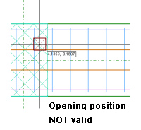
The conditions under which an opening is considered to be correctly defined may vary along the length of the frame (for example, if another opening is introduced very close to it, the stirrups of both openings could overlap, which would generate an undefined situation). If an opening cannot be processed, it is marked with a red dot and an error message is displayed when the mouse cursor is placed over it; and its effects on the previously introduced reinforcement disappear until the opening is deleted or the error is resolved.
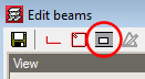
The options to define the openings are located in the Openings floating menu, which can be activated by selecting the , button, that appears in the top buttons bar next to the transverse reinforcement edition option.
Introducing the openings and defining their reinforcement
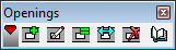
The Openings floating menu contains five options:
New opening Three steps must be followed to introduce a new opening:
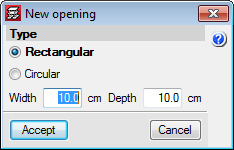
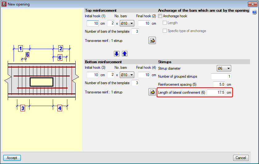
Select the type of opening and its dimensions Once the New opening button () is selected, the New opening dialogue appears on screen, in which the type of opening (Rectangular or Circular) and its dimensions are defined.
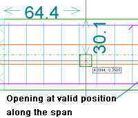
Confirmation of the position of the opening on the span Once the dimensions of the opening have been introduced, users select the position (using the mouse cursor) on the frame at which it is to be introduced. During this process, the program displays the opening with the shape and size that have been specified, and its coordinates, which depend on the position of the mouse cursor. Unless the opening cannot be introduced at the current position of the cursor, two coordinates will always be displayed:
The distance with respect to the support
The distance with respect to the top face of the beam
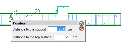
To confirm the position of the opening, simply click on the left mouse button so a panel appears allowing for the numerical position of the opening to be defined.
Defining the reinforcement of the opening The reinforcement is composed, for both rectangular and circular openings, of:
Top reinforcement
Bottom reinforcement
Stirrups applied to the corresponding zone of the opening
Anchorage of bars that are cut due to the interaction with the opening (only affects skin reinforcement bars).
The Length of lateral confinement, which is required in the dialogue box in which the reinforcement of the opening is defined, refers to the zones at either side of the opening. The same stirrup arrangement is used in both zones defined by the lateral confinement length as before the opening was introduced, but with the stirrup diameter and spacing defined for the opening. These zones are used to guarantee the shear is transmitted correctly between the zone of the beam without an opening and the zone with.
Two independent stirrup arrangements can be defined for the parts above and below the opening, and the template of the opening (indicates the points which can tie the stirrups or cross-ties) must be compatible with the base reinforcement template of the span in which it is located (to avoid there being loose stirrups). The number of reinforcement bars of the opening must be greater than or equal to the number of reinforcement bars of the template to guarantee there is a bar at all the positions at which the stirrups are held.
Edit opening This option displays the same dialogue in which the reinforcement of the opening has been defined using the New opening () option.
The reinforcement of the opening can also be edited from:
The edition of the longitudinal reinforcement of the frame ( button on the top bar of the beam editor > Edit).
This way a panel is displayed which allows users to edit the reinforcement of the opening.
The edition of the transverse reinforcement of the frame (botón button on the top bar of the beam editor > Edit).
Allows users to edit the transverse reinforcement of the opening, the additional reinforcement and anchorage.
Edit opening and assign Allows users to match the type of opening and their reinforcement to several openings. First of all, users must select the opening which is to be taken as the source opening (which will allow for any parameters to be edited) and then, select the openings to be matched. This selection can be carried out one-by-one, or using a capture window. Those which are the same are displayed in orange and those that are different in yellow.
Move opening Allows users to displace the opening within the same span. Simply select the opening and drag it to its new position. When the opening is placed in its new position, the program applies the same considerations as when a new opening is introduced.
Delete opening Users can delete the selected opening or openings. Multiple openings can be selected for deletion (using a capture window), or deleted individually.
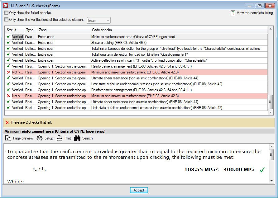
U.L.S. checks of the openings
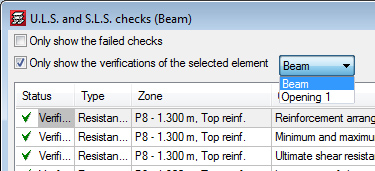
The U.L.S. checks of the introduced openings can be consulted using the existing options in the beam editor, (U.L.S. checks at the worst case point) and (U.L.S. checks at a point) buttons. In the case of the worst case point, all the checks of the openings the beam may have are added to the checks of the beam. When consulting the checks at a point, the opening can be selected directly.
When checking a beam with openings, worst case checks of the beam may appear in the zone in which the opening is situated because the program considers that the zone of the opening should meet the requirements of the section with the opening as well as the section without it.
An element filter has been implemented to help when consulting the checks of the openings using the worst case point option ().
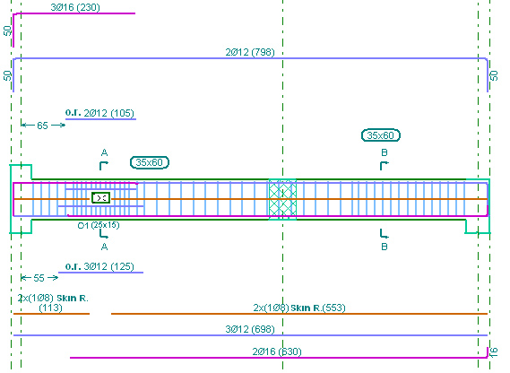
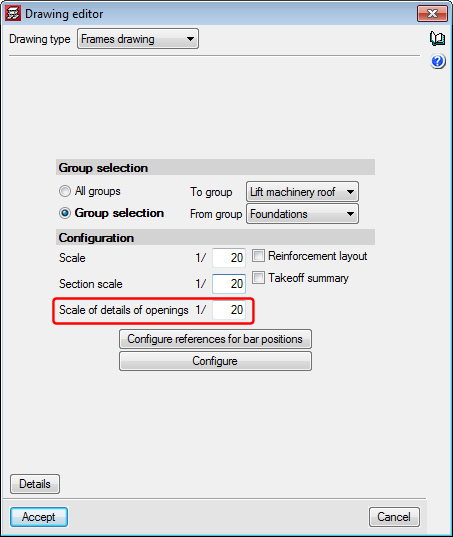
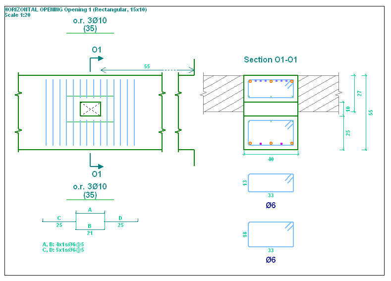
Reinforcement details of the openings in drawings
If a frame contains openings, the details of the opening are automatically generated integrated within the details of each frame. The scale of the detail of the opening can be configured by users.
Code implementation. NSR-10 (Colombia) (Título C ‑ Concreto estructural)
Continuous beams now includes the following new features:
Re-design frame reinforcement
Join assembly or skin reinforcement
Conservation of the lateral menu configuration
These improvements are the same as those which have been implemented in the CYPECAD's beam editor (except the option to Block reinforcement, which, given how it operates, is not applicable to this program).
We use cookies on our website to give you the most relevant experience by remembering your preferences and repeat visits. By clicking “Accept All”, you consent to the use of ALL the cookies. However, you may visit "Cookie Settings" to provide a controlled consent.
This website uses cookies to improve your experience while you navigate through the website. Out of these, the cookies that are categorized as necessary are stored on your browser as they are essential for the working of basic functionalities of the website. We also use third-party cookies that help us analyze and understand how you use this website. These cookies will be stored in your browser only with your consent. You also have the option to opt-out of these cookies. But opting out of some of these cookies may affect your browsing experience.
Strictly necessary cookies are absolutely essential for the website to function properly. These cookies provide the basic functions and security features of the website, anonymously.
Cookie
Duration
Description
cookielawinfo-checkbox-analytics
11 months
This cookie is set by GDPR Cookie Consent plugin. The cookie is used to store the user consent for the cookies in the category "Analytics".
cookielawinfo-checkbox-functional
11 months
The cookie is set by GDPR cookie consent to record the user consent for the cookies in the category "Functional".
cookielawinfo-checkbox-necessary
11 months
This cookie is set by GDPR Cookie Consent plugin. The cookies is used to store the user consent for the cookies in the category "Necessary".
cookielawinfo-checkbox-others
11 months
This cookie is set by GDPR Cookie Consent plugin. The cookie is used to store the user consent for the cookies in the category "Other.
cookielawinfo-checkbox-performance
11 months
This cookie is set by GDPR Cookie Consent plugin. The cookie is used to store the user consent for the cookies in the category "Performance".
viewed_cookie_policy
11 months
The cookie is set by the GDPR Cookie Consent plugin and is used to store whether or not user has consented to the use of cookies. It does not store any personal data.
Functionality cookies help to carry out certain functions, such as sharing the website content on social media platforms, collecting feedback, and other third-party features.
Performance cookies are used to understand and analyse the key performance indicators of the website, thus helping to provide a better user experience for visitors.
Analytics cookies are used to understand how visitors interact with the website. These cookies help provide information on website metrics, such as the number of visitors, bounce rate, traffic source, etc.
Advertisement cookies are used to provide visitors with relevant ads and marketing campaigns. These cookies track visitors across websites and collect information to provide customized ads.