
Composite slabs
With the "Composite slabs" module, CYPECAD analyses and designs composite slabs ("steel deck").
Composite slab floors consist of a concrete slab and a ribbed plate that is used as formwork for the concrete slab. The plate can be used in one of the following ways.
- Only as a form deck: During the construction phase, the deck alone resists its self weight, the weight of fresh concrete and the construction live loads. During the service phase, it is only the reinforced concrete slab that has a resisting function.
- As a supporting plate (mixed behaviour): During the construction phase, the deck works as a form deck as in the previous case. During the service phase, the deck is considered to combine structurally with the hardened concrete, acting as reinforcement in tension, resisting the positive moments in the finished floor slab.
Composite slabs can be applied to building structure projects where the imposed loads are predominantly static, including industrial buildings whose floors may be subjected to moving loads.
The total depth of the composite slab, the thickness over the plate ribs and the minimum height of the bolts over the plate ribs (in the case of composite beams) are limited.
The sheet can be supported on metal beams, composite metal beams, concrete beams or walls, among other options, and a minimum delivery is required, which the program does not currently cover.
Entering composite slabs
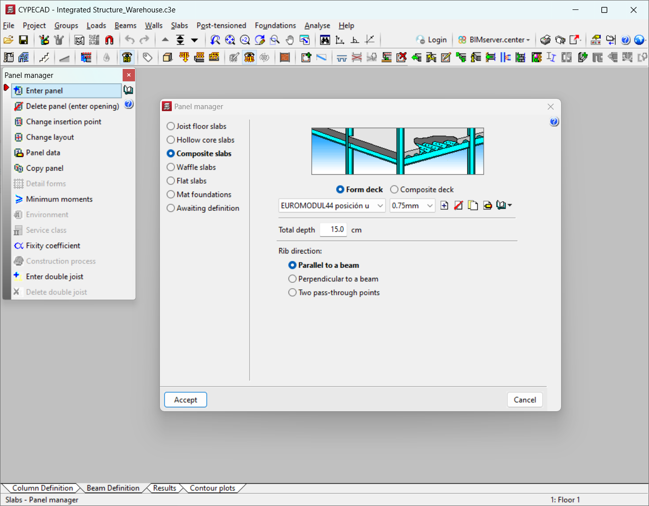
To select the type of "Composite slabs", click on the "Slabs" menu and then on "Panel manager". Here, the "Enter panel" option opens the "Panel manager" window, where the "Composite slabs" option can be selected.
The following data must be defined when entering "Composite slabs" type panels:
- How to work the sheet metal
There are two options to choose from: "Form deck" and "Composite deck". The type of form deck or composite deck must be selected from those available in the library, or a "New series" must be created.
- Total depth
The total depth of the panel, which is made up of the depth of the sheet plus the thickness of the concrete compression layer, must be established. - Rib direction
Three options are available: "Parallel to a beam", "Perpendicular to a beam" and "Two pass-through points".
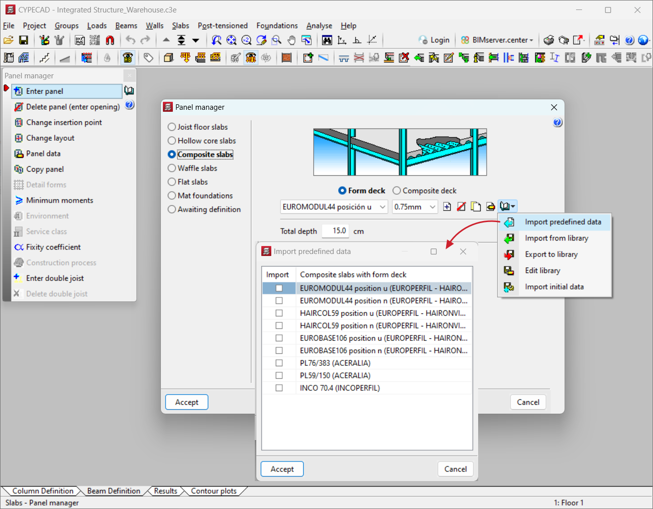
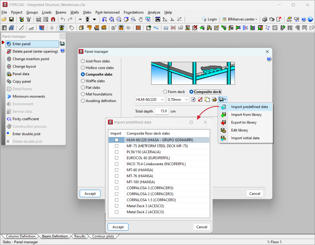
From "Management of the section library" users can "Import predefined data" and select, depending on the way of working the sheet metal ("Form deck" or "Composite deck"), among those available from the different manufacturers.
Analysis and design process for composite slabs
The analysis and design process is carried out in two phases:
- In the execution phase
- When analysing the strength of the plate, the weight of the concrete, the steel plate and the design loads are taken into account.
- For the deflection analysis, the construction loads are not taken into account.
- An internal fixity coefficient of 0 is considered for the walls with their perimeter beams (ribbed slabs).
- There is an option to design the plate in case of non-compliance with an ultimate limit state or a deflection limit state, or the option of analysing the gap between girders without designing the plate. If the first case does not give a valid result, then the gap between girders is calculated.
- In the service phase
- The service phase starts from the plate that was analysed in the previous phase.
- By default, the program assigns a fixity coefficient of 0 to the panels, so that the load distribution to the steel beams on which the slab rests is carried out according to the theoretical span width, and to avoid the appearance of positive moments in intermediate supports. Once the first analysis and design of the beams have been carried out, the fixity coefficient can be changed to another one (between 0 and 1) and the analysis can be repeated.
Results output
Reports
The following reports are available:
- Composite slab quantities
The quantities of each slab, a summary by groups or a total summary of the job can be obtained. - Forces in composite slabs
As well as the force envelopes (moments, shear and torsional stresses), the stresses by simple loads and by the combination of loads selected can be consulted. They can be exported in DWG, DXF or PDF format. - Composite slab reinforcement quantities
Allows users to select the "Complete diameter table" option, and if they wish, by "Lengths" or by a "Totals Summary". The floors to be obtained can also be selected.
Exporting composite slabs to IFC
Exporting to IFC (Industry Foundation Classes) format includes the sheet metal and the concrete layer of the composite slabs.
User license
For CYPECAD to be able to analyse and design composite slabs, the user license must include the "Composite slabs" module as well as CYPECAD.
Other features
To access other features offered by the program, there are several modules which can be found on the "CYPECAD modules" page.