Beam editing
The "Beam editing" options are available in the corresponding menu of the "Bars" group on the top toolbar, within the "Geometry" tab (in the "Structure" tab).

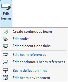
The options available in this menu are as follows:
- Create continuous beam
- Edit nodes
- Edit adjacent floor slabs
- Edit beam references
- Edit continuous beam references
- Beam deflection limit
- Edit beam environment
Each of these features is detailed below.
Create continuous beam
This option allows you to create a continuous beam. The beams that form the new continuous beam are selected using the left mouse button, then the right button is clicked.
The selected beams must be connected so that the end node of one beam is the start node of the next. In addition, all beams must be of the same material class, and the local XZ plane of each beam must lie in a vertical plane.
Edit nodes
The "Edit nodes" option allows you to edit the geometry of a node in a continuous beam, in case you want to use a geometry different from the one automatically determined by the program.
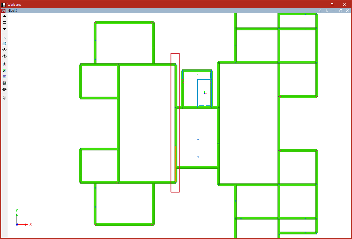
Nodes are selected with the left mouse button or by drawing a selection area, then the selection is confirmed with the right mouse button.
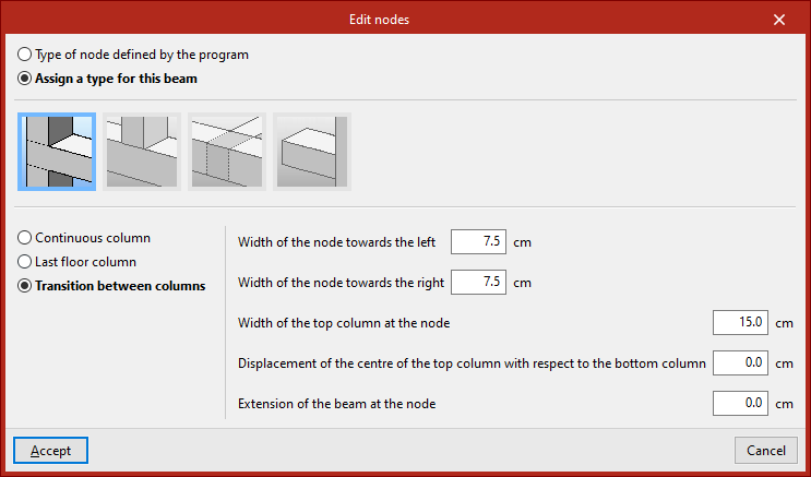
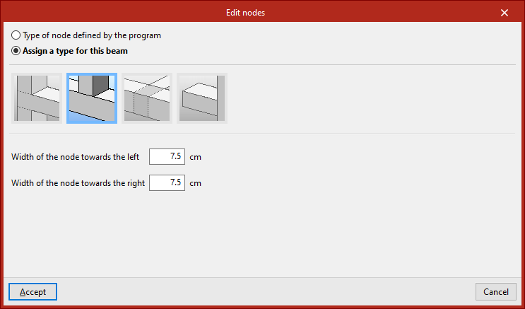
In the window that appears, you can keep the "Type of node defined by the program" or "Assign a type for this beam", indicating whether it is a "Column", "Short column", "Support on beam" or "Cantilever".
For each of these cases, parameters that define the node are specified in the lower section, such as "Width of the node towards the left" and "Width of the node towards the right".
The node geometry affects the clear span of the beams as shown in the beam reinforcement editor, and therefore the length of the reinforcement bars.
Then, click "Accept".
Edit adjacent floor slabs
This option allows you to edit the floor slabs adjacent to the beams. This way, you can define the depth of flat beams, as well as specify the slabs shown in the beam detailing drawing. It is also considered in the fire resistance check for steel beams.
Beams are selected with the left mouse button or by drawing a selection area, then confirmed with the right mouse button.
In the window that appears, there are several options:
- First, an "Unconnected beam" can be defined.
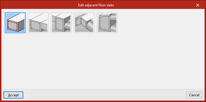
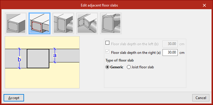
- If "Level slabs" is selected, you can input the "Slab depth to the left" and "to the right", as well as define the "Type", either "Generic" or "One-way", including the "Height" and the "Width of the reduced hollow block".
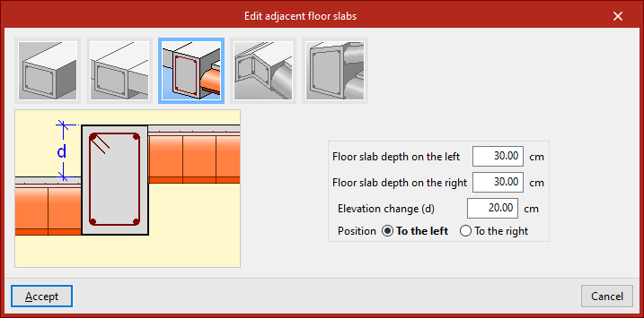
- In the case of "Slabs with step", in addition to the "Depth", the "Step height" and its "Position", "To the left" or "To the right", are indicated.
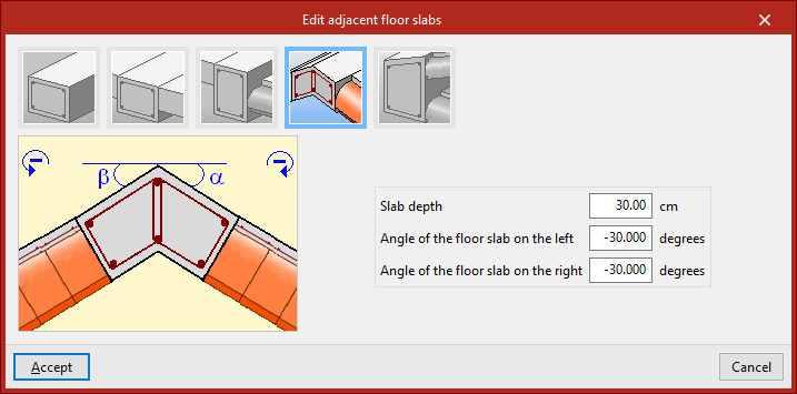
- You can also define a "Meeting of inclined slabs" by inputting the "Slab depth", the "Inclination angle to the left" and "to the right".
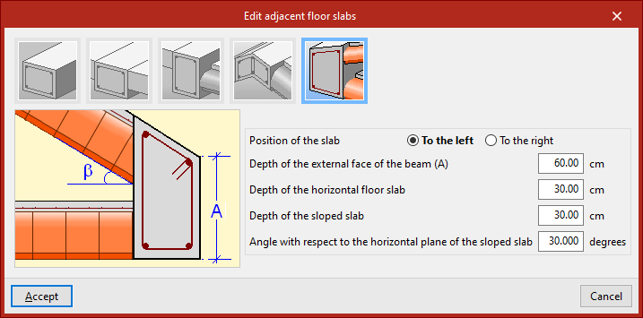
- For an "Eaves meeting of sloped roof", in addition to the "Position of the slab", define the "Depth of the external face of the beam", the "Depth of the horizontal floor slab", the "Depth of the sloped slab", and the "Angle with respect to the horizontal plane of the sloped slab".
Once the adjacent slabs are defined, click "Accept".
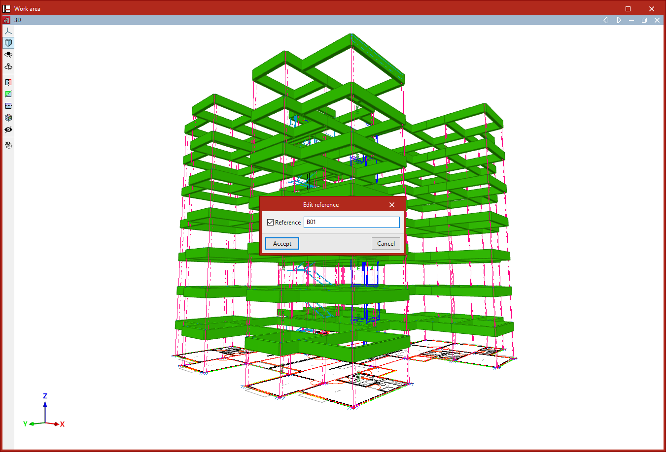
Edit beam references
To edit the reference of a beam, select this option and then click on the beam. Once activated, type in the desired "Reference" and then click "Accept".
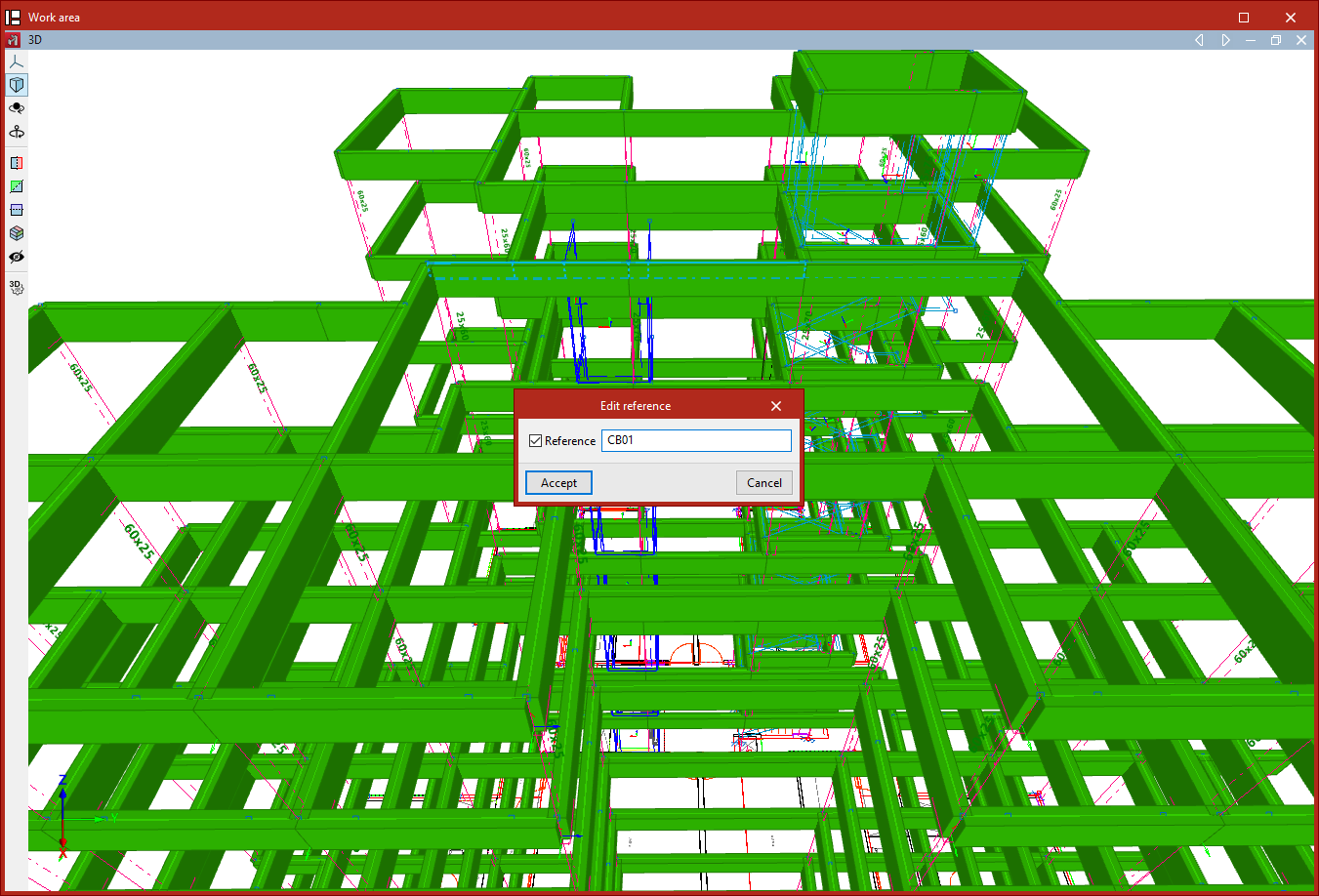
Edit continuous beam references
This option allows you to edit the references of continuous beams. Similarly, click on the continuous beam, activate and type in the desired "Reference", and then click "Accept".
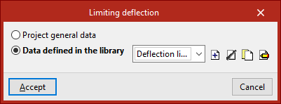
Beam deflection limit
This option allows you to specify whether the deflection limit for the selected beam is defined according to the "General project data" or from "Data defined in the library", which can be configured specifically.
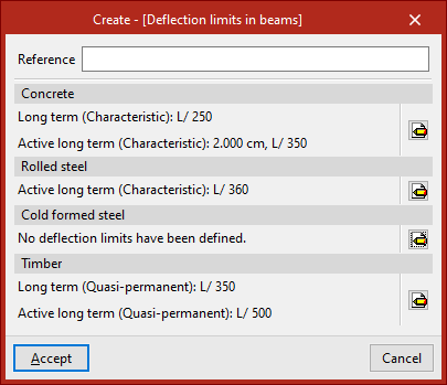
In the latter case, a set of "Deflection limits in beams" must be created with the available options for the different materials shown ("Concrete", "Rolled steel", "Cold-formed steel", and "Timber").
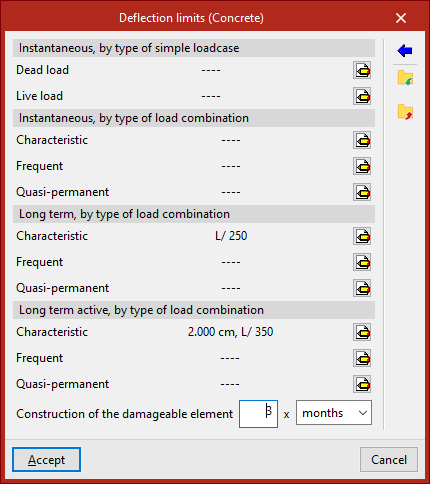
The following deflection limits can be specified:
- Instantaneous, by type of simple load case (Dead load, Live load)
- Instantaneous, by type of load combination (Characteristic, Frequent, Quasi-permanent)
- Long term, by type of load combination (Characteristic, Frequent, Quasi-permanent) (for "Concrete")
- Long term active, by type of load combination (Characteristic, Frequent, Quasi-permanent)
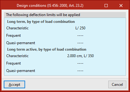
The assistant on the right allows you to import the design conditions from the concrete standard selected in the "General data" tab under "Project".
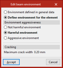
Edit beam environment
This option allows you to specify whether the "Environment defined in general data" is used for the selected beam or if you want to configure it specifically by choosing "Define environment for the element".
In the second case, depending on the selected code, it may be necessary to define the "Environment aggressiveness" or the "Environment class" and the "Designation" from the available ones, which will determine or allow input of the "Maximum crack width", as indicated in the "Cracking" section.