Checking buckling contour plots
Isovalues for buckling analysis can be viewed using the following option, available in the "Buckling" section of the top toolbar, within the "Analysis" tab (under the "Structure" tab).

Contour plots
The program enables the analysis of buckling in shells.
Using the "Buckling" option in the "Shells" section of the "Properties" tab, you can select the sheets to be included in the linear buckling analysis.
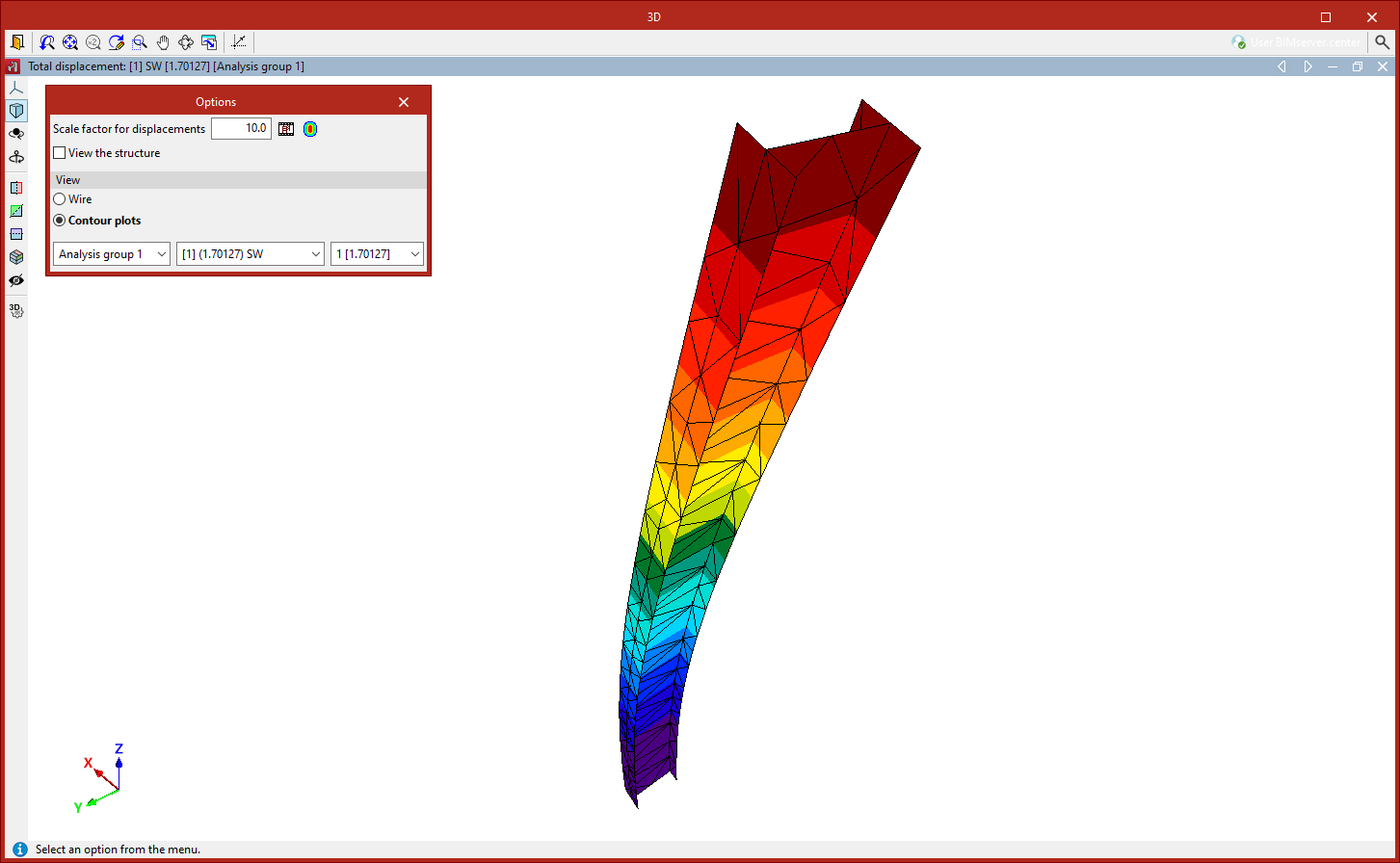
Once the buckling analysis has been carried out, the "Contour plots" option in the "Analysis" tab allows you to view the contour plots of the deflection for the different buckling modes in a pop-up window.
A pop-up dialogue box appears in this window to configure various "Options":
- Firstly, you can adjust the "Scale factor for displacements" and the "Colours for the representation of contour maps", as well as view an "Animation" of the deformed shape.
- The "View structure" option allows you to display the original geometry of the structure on screen.
- You can select the "Display" option in "Wire" mode, which shows only the outlines of the mesh elements, or "Contour plots" mode, which colours the elements in full.
- Use the drop-down menus at the bottom to select the analysis group, load combination and vibration mode you wish to view. The value of the calculated critical load factor is shown in brackets.