
Creating and editing rigid diaphragms
Rigid diaphragms are created and edited using the options available in the "Diaphragms" group on the top toolbar, within the "Properties" tab (under the "Structure" section).

Relative displacements between nodes belonging to the same rigid diaphragm are restricted. Therefore, each diaphragm can only rotate and move as a single unit.
This simplifies the analysis in structures where rigid diaphragms are assumed to exist, such as in each floor slab, which can be considered non-deformable in their plane.
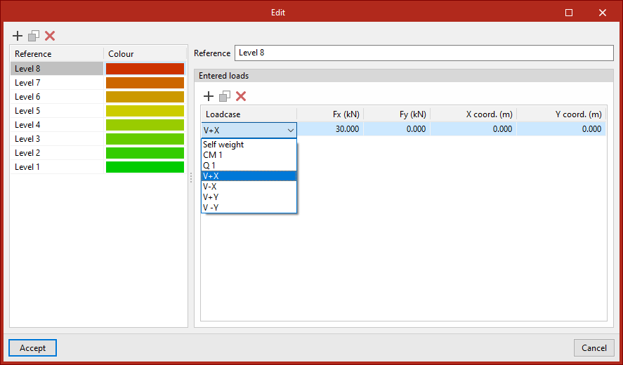
Edit
Allows you to manually create and/or edit the diaphragms, including their "Reference" and "Colour".
In addition, loads can be defined for each diaphragm. To do this, in the "Entered loads" table, you can select the "Loadcase", the load in the global X-direction ("Fx"), the load in the global Y-direction ("Fy") and the coordinates of the point of application ("X-coord." and "Y-coord.").
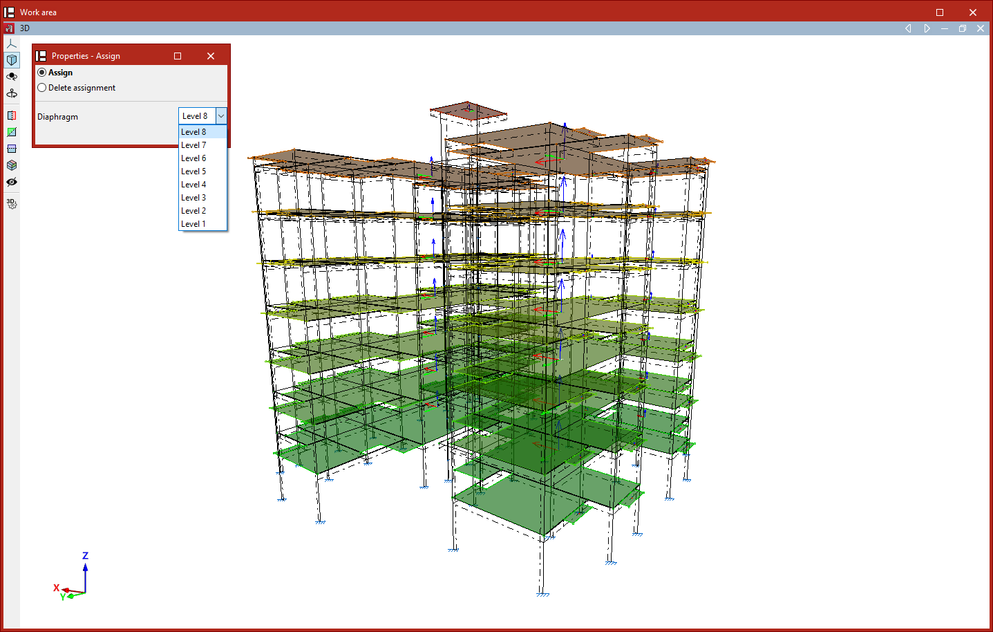
Diaphragm
This option allows you to "Assign" the "Diaphragm" selected from the drop-down menu to the nodes or shells selected in the workspace.
You can also "Remove assignment" by ticking the relevant option in the "Properties - Assign" pop-up window that appears when you select this option.
Generate by level
If levels have been defined in the project (using the "Levels" option in the "Planes" menu on the "Geometry" tab), this tool automatically generates a diaphragm for each level and assigns that diaphragm to all nodes on that level.
In the process, any previously defined diaphragms will be deleted. The program will display a dialogue box to warn you of this before continuing.