
Checking displacements and rotations in the nodes
The displacements and rotations at the nodes after the analysis of the structure can be viewed with the following option, which is available in the "Stress / Strain" group of the upper toolbar in the "Analysis" tab (in the "Structure" tab).

Displacements
The "Displacements" option is used to check the displacements and rotations of the two end nodes of a bar.
By left-clicking on a bar, the program will display on the screen the displacements and rotations in the three directions of space of each of the end nodes.
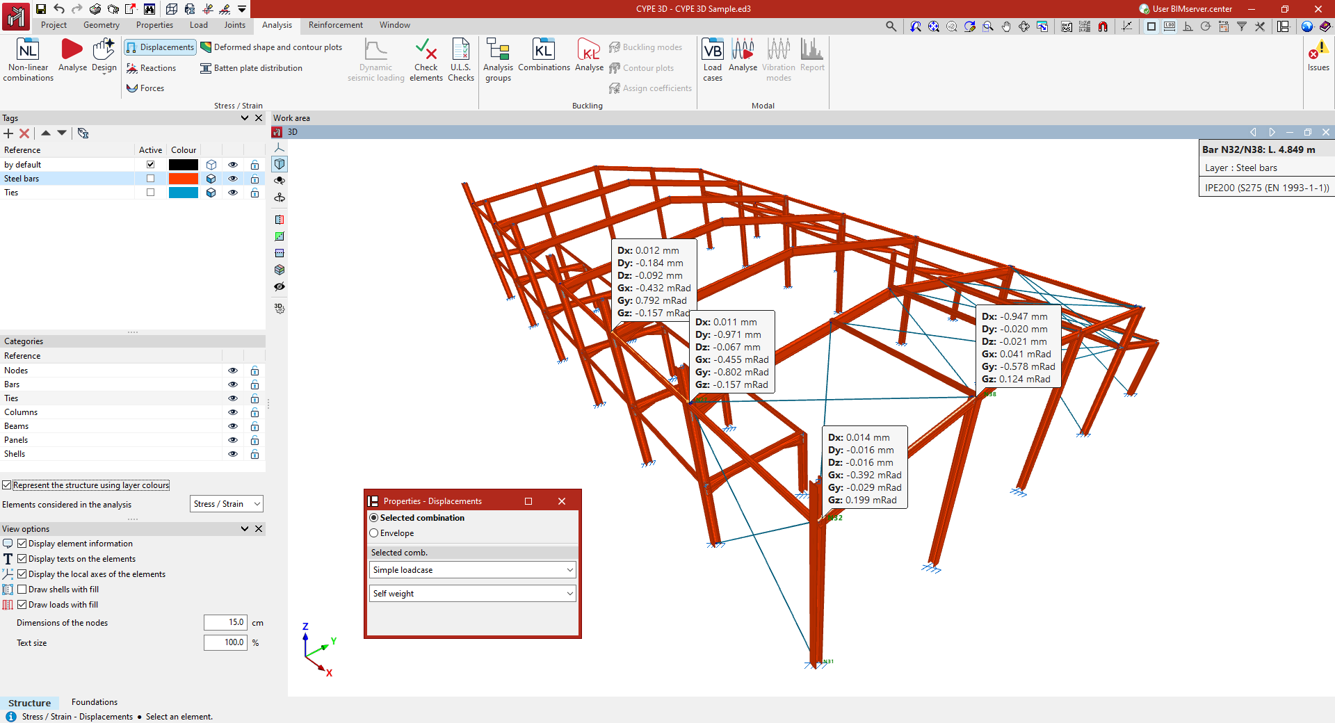
The values shown refer to the global axes of the model. The positive sign of a displacement refers to the positive direction of each axis. On the other hand, a rotation referred to an axis indicates a rotation around that axis, and is positive in a counter-clockwise direction.
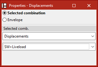
In the "Properties - Displacements" dialogue box that appears, there are two options to choose from:
- If "Selected combination" is chosen, the loadcase or combination of loadcases to be checked must be specified in the drop-down menus below:
- By selecting "Simple loadcase" in the first drop-down menu, a specific loadcase can then be chosen from those available.
- By selecting the "Displacements" group in the first drop-down menu, a specific combination of loadcases belonging to this group can then be chosen.
- The groups of loadcase combinations associated with the different materials ("Rolled and reinforced steel", "Cold formed steel", "Wood", "Aluminium" and "Concrete") are also available.
- If "Envelopes" is chosen, the program shall display the maximum and minimum values of the envelope of loadcase combinations. These values cannot be simultaneous, i.e. the maximum displacement or rotation value in a given direction does not have to occur simultaneously with the values in another direction.
To hide the displayed information, left-click on the bar again.