Defining external fixity in nodes
The external fixity in the nodes of the structure is defined with the following option, available in the "Nodes" group of the top toolbar, in the "Properties" tab (in the "Structure" tab).

External fixity
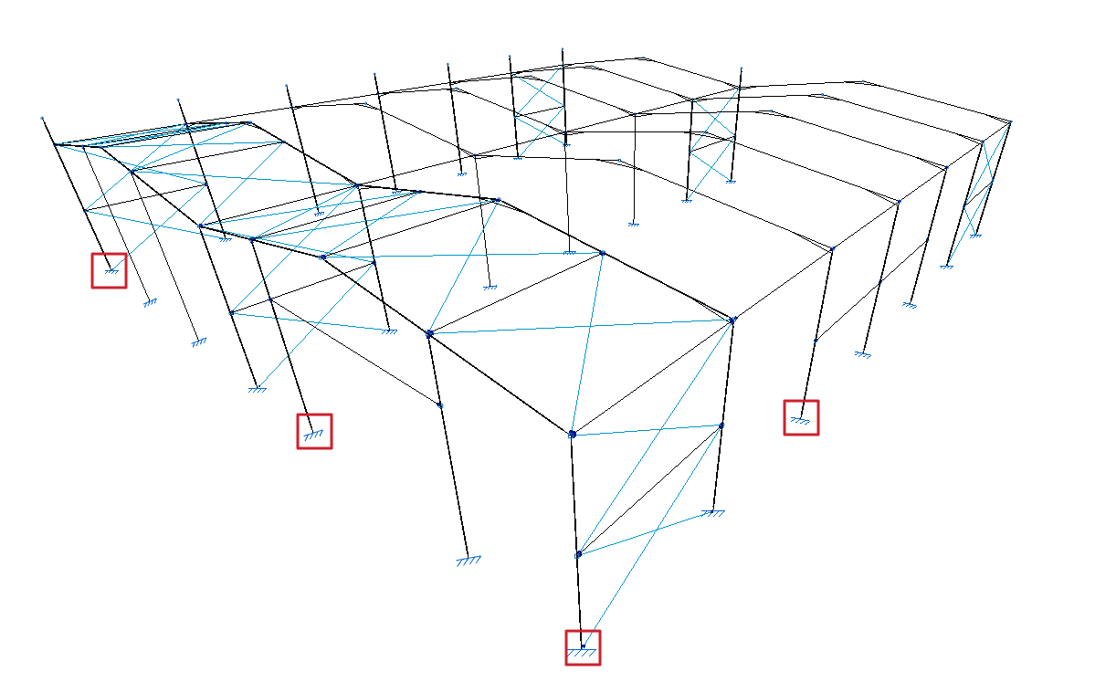
Enters external fixity. External fixities restrict the displacement or rotation of the nodes of the structure and correspond to the supports on the ground and on other elements outside the model.
To do this, after clicking on the option, select the nodes where the connection is to be defined one by one or draw a selection box that covers them with the left mouse button. Finally, click on the right mouse button.
The program will open a window where the type of "External fixity".
Free
By default, a newly inserted node will be "Free", i.e. it will not have any external fixities.
The other options are used to define external fixity in the node.
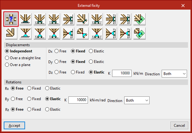
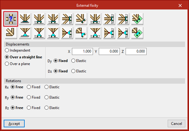
Generic
The "Generic" option manually defines the restrictions on "Displacements" and "Rotations" in the three directions of the space.
Displacements
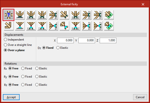
"Displacements" can be "Independent", "Over a straight line" or "Over a plane".
In case they are defined as "Independent", the behaviour of the displacements in the three axes, "Dx", "Dy" and "Dz", is specified:
- If "Free", the displacement in that direction shall not be constrained.
- If "Fixed", the displacement is constrained and takes a fixed value. By default, this value is null, unless the "Prescribed displacements" option has been used from the "Load" tab, in which case it will assume this value.
- If "Elastic" is selected, the program assumes an elastic support in that direction. On the right, the elastic constant of the support is written in the units indicated, and its "Direction" is specified (it can act in "Both" directions or only in "Negative" or "Positive" directions).
If the "Displacements" are defined "Over a straight line", the node can only be displaced in the direction of the director vector defined by the X, Y and Z components entered on the right. In the directions perpendicular to this line, users specify whether the support is "Fixed" or "Elastic".
If the "Displacements" are defined "Over a plane", the node can only be displaced in the plane perpendicular to the vector defined by the X, Y and Z components entered. Similarly, in the direction perpendicular to the plane, users indicate whether the support is "Fixed" or "Elastic".
Rotations
In the "Rotations", "Gx", "Gy" and "Gz", choose "Free" if the rotation is not constrained in the indicated direction, "Fixed" if the rotation is constrained and takes a fixed and null value, or "Elastic" if the constraint to the rotation is elastic, in which case the constant governing the rotational stiffness of the support must be written and, in addition, its "Direction" is specified (it may act in "Both" directions or only in "Negative" or "Positive" directions).
The other options in the "External fixity" panel correspond to predefined external fixities that simplify data entry to speed up the process.
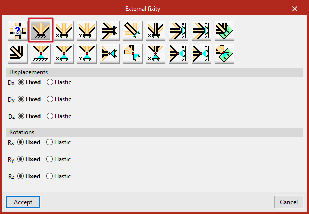
Fixity
The "Fixity" option prevents "Displacements" ("Dx", "Dy" and "Dz") and "Rotations" ("Gx", "Gy" and "Gz") in the three directions of the selected node.
Each prevented displacement or rotation must be defined as "Fixed" or "Elastic".
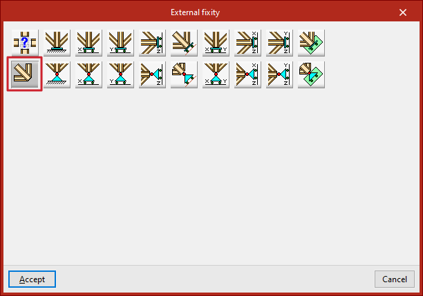
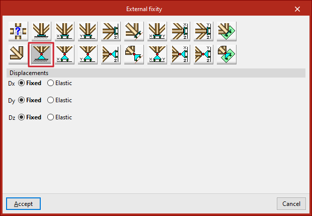
Pinned connection
The "Pinned connection" option prevents only the "Displacements" ("Dx", "Dy" and "Dz") in the three directions of the selected node.
Each prevented displacement or rotation must be defined as "Fixed" or "Elastic".
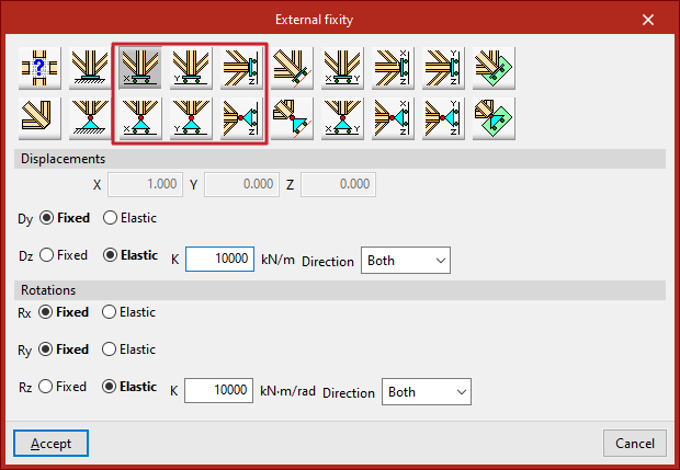
Free displacements on a straight line in X, Y or Z directions
These options define free displacements over a straight line in the global directions X, Y or Z.
The options in the first row constitute freely movable fixities and also constrain the rotation:
- Free displacement over a straight line in X direction
- Free displacement over a straight line in Y direction
- Free displacement over a straight line in Z direction
Those in the second row constitute supports with free displacement and hold the rotations without constraint:
- Free displacement over a straight line in the X direction with unrestrained rotations
- Free displacement over a straight line in the Y direction with unrestrained rotations
- Free displacement over a straight line in the Z direction with unrestrained rotations
In all these cases, the components of the line's director vector are already defined in the numerical fields in grey. Users simply indicate whether the displacement or rotation in each of the directions shown is "Fixed" or "Elastic".
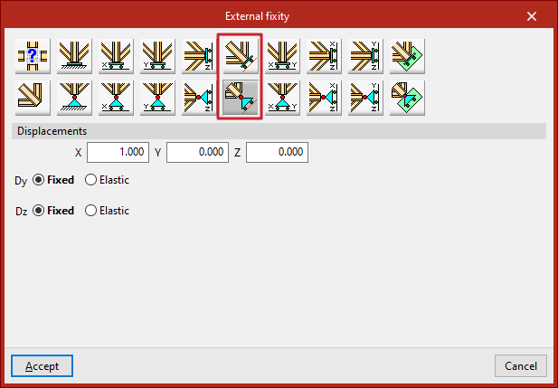
Free displacements over any straight line
The following options define a free displacement over any straight line, with coerced rotations or with uncoerced rotations:
In all these cases, the components of the line's director vector are already defined in the numerical fields in grey. Users simply indicate whether the displacement or rotation in each of the directions shown is "Fixed" or "Elastic".
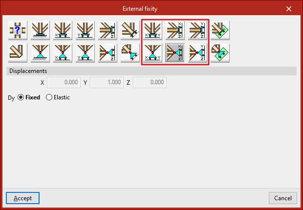
Free displacements on a plane parallel to the XY, XZ or YZ axes
The following options are used to define free displacements in a plane parallel to the global XY, XZ or YZ axes.
The options in the first row constitute freely displacement fixities and also constrain rotations:
- Free displacement in a plane parallel to XY axes
- Free displacement in a plane parallel to XZ axes
- Free displacement in a plane parallel to YZ axes
Those in the second row constitute supports with free displacement and hold the rotations without constraint:
- Free displacement in a plane parallel to the XY-axes with unconstrained rotation
- Free displacement in a plane parallel to the XZ-axes with unconstrained rotation
- Free displacement in a plane parallel to the YZ-axes with unconstrained rotation
In all these cases, the components of the vector perpendicular to the plane are already defined in the numerical fields in grey. Users simply indicate whether the displacement or rotation in each of the directions shown is "Fixed" or "Elastic".
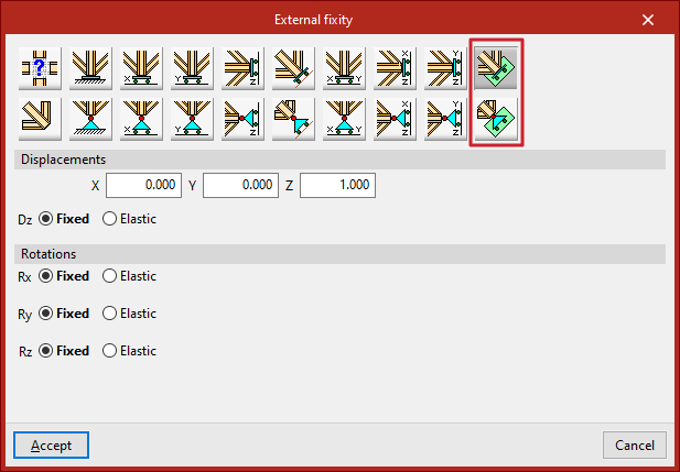
Free displacements over any plane
Finally, a free displacement on any plane can be defined, with forced or uncoerced rotations:
- Free displacement in any plane
- Free displacement in any plane with unconstrained rotations
The components of the vector perpendicular to the plane must be entered and users must indicate whether the displacement or rotation in each of the directions shown is "Fixed" or "Elastic".