
Dynamic earthquake loading analysis: activation and configuration
The dynamic earthquake loading analysis is activated in the "Project" tab (within the "Structure" tab) by selecting the "General data" option from the "Project" group on the top toolbar.

"With dynamic earthquake loading" option
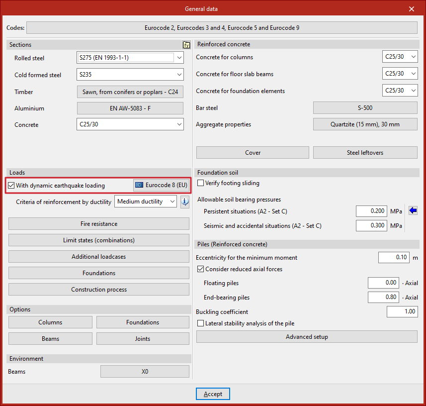
Within the "General data" window, under the "Actions" section, tick the "With dynamic earthquake loading" box so the program carries out the dynamic earthquake analysis in the structural analysis.
This opens the "Code for the calculation of seismic loading" window.
Then, the program enables a button with the name of the selected code, allowing you to go back to the window to make adjustments to its configuration.
Seismic code configuration for calculating seismic loading
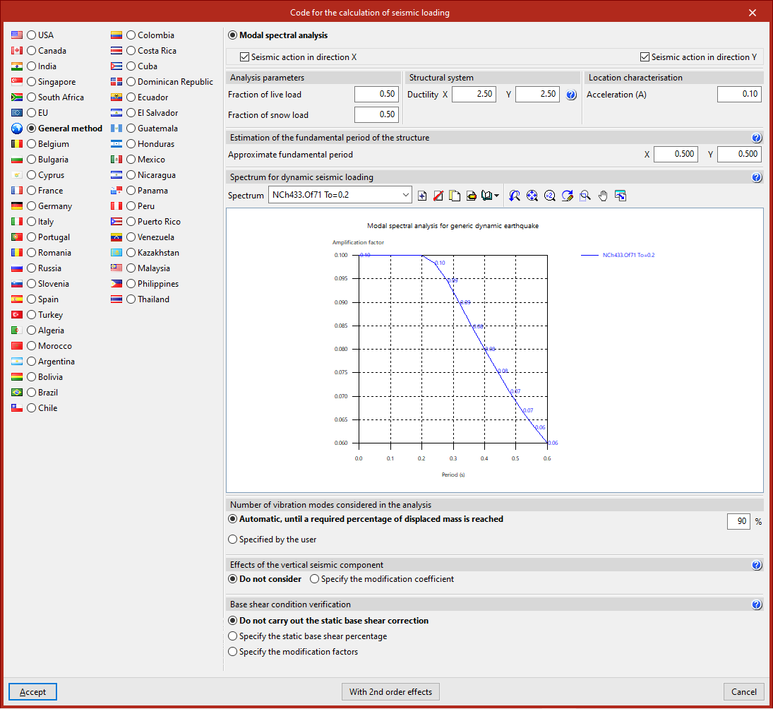
In the "Code for the calculation of seismic loading" window, the country or region is first selected from the left-hand column. The codes associated with each one appear in the top right.
After selecting the desired code, the related parameters can be configured using the other options in the panel.
You may also select the "General method", which allows a custom seismic spectrum to be defined.
Example of code configuration for calculating the seismic loading
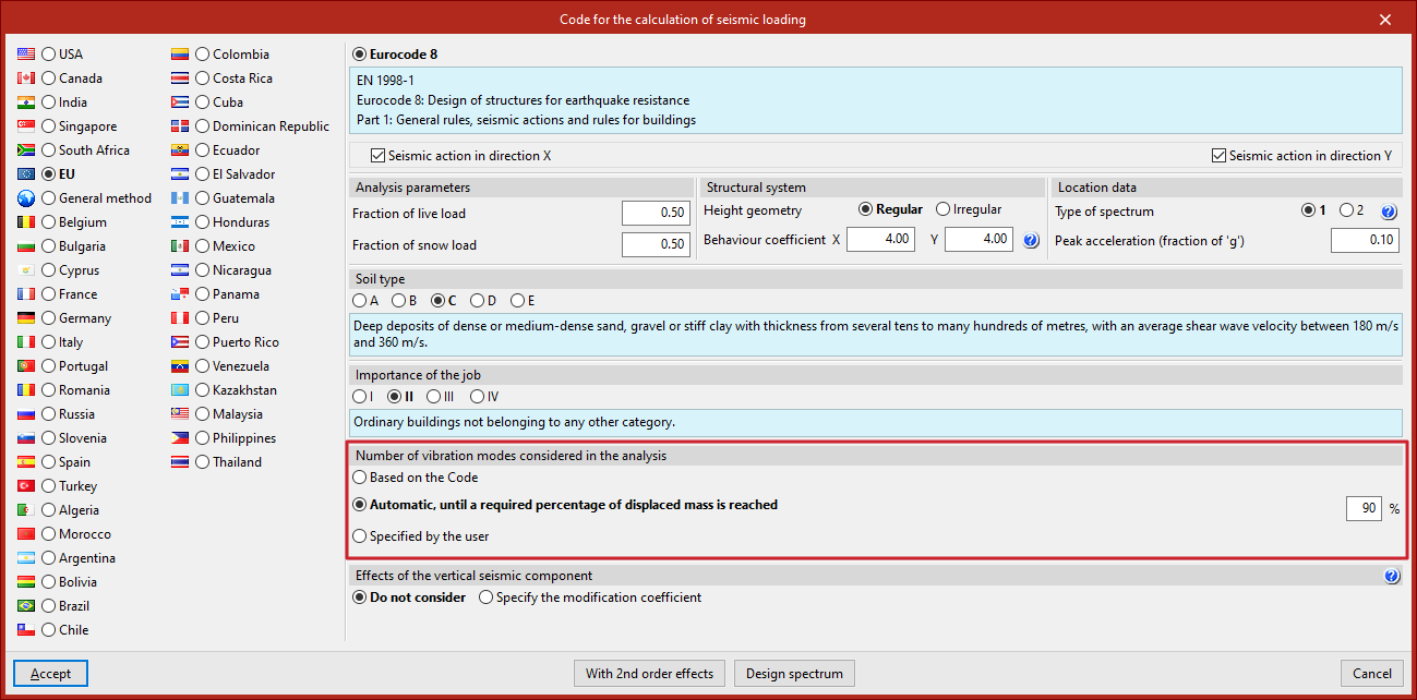
The configuration options available depend on the selected code. In this example, the "EU" and "Eurocode 8" options are selected:
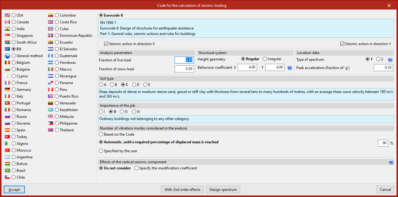
- The checkboxes at the top can be ticked to indicate that the calculation of "Seismic action in direction X" and "Seismic action in direction Y" is required.
- In the "Analysis parameters" section, the "Fraction of live load" and the "Fraction of snow load" are entered, used to assess the building's mass during seismic action.
- Next, the "Structural system" of the project is described. Its "Height geometry" can be either "Regular" or "Irregular".
To enter the "Behaviour coefficient" in X and Y, the help button can be used. The program suggests recommended values depending on whether it is a "Concrete structure", "Steel structure", or one of the available "Composite structures"; the "Structural type"; and the "Ductility", whether medium or high.
- In the "Location data" section, specify the "Type of spectrum", which depends on the magnitude of surface waves recorded in a given area. Again, this information can be accessed via the help button.
Below this, the peak acceleration is indicated as a fraction of gravitational acceleration ("Peak acceleration (fraction of ‘g’)").
- Then, define the "Soil type" and the "Importance of the project" by selecting the relevant options. The program provides explanatory texts when selecting each option to help identify the scenario the project falls into.
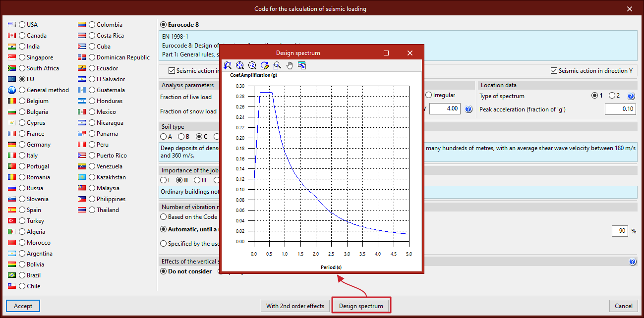
Design spectrum
The button at the bottom allows you to consult the automatically generated "Design spectrum" based on the selected options.
Number of vibration modes included in the analysis
The modal spectral dynamic analysis must include all modes that contribute significantly to the structure's dynamic response. For this, the "Number of vibration modes considered in the analysis" must be specified in the corresponding section.
- If "Based on the code" is selected, the program determines the number of modes according to the selected seismic code.
- If "Automatic, until a required percentage of displaced mass is reached" is selected, the desired percentage must be entered. This is usually high to ensure a meaningful analysis.
- If "Specified by the user" is chosen, the number of modes is entered directly based on your own criteria. This number affects the analysis time and should remain within a reasonable range to ensure an adequate percentage of displaced mass, verifiable in the reports.
Effects of the vertical seismic component
As for the "Effects of the vertical seismic component", you can select "Do not consider" in most cases.
However, if you wish to include it, you must "Specify the modification coefficient" by selecting the appropriate option and adjusting the factor for permanent loads in the seismic combinations.
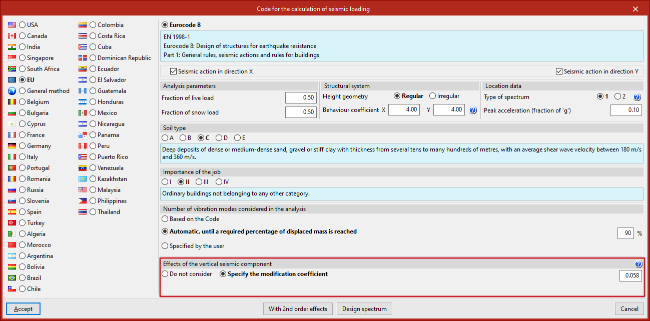
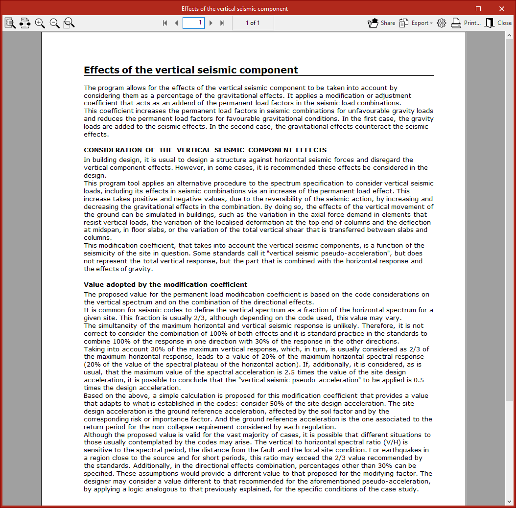
Further information on the "Consideration of the effects of the vertical seismic component" and the "Value of the modification coefficient" can be accessed via the help button.
Second order effects
By default, the analysis is carried out "Without 2nd order effects". If you wish to consider them, access the "Second order effects" configuration window using the button at the bottom, and tick the box to "Consider second-order effects". The program will use the P-delta method to estimate them.
You must also specify the "Value to multiply displacements", which, in structures with steel columns, may be set to 1.
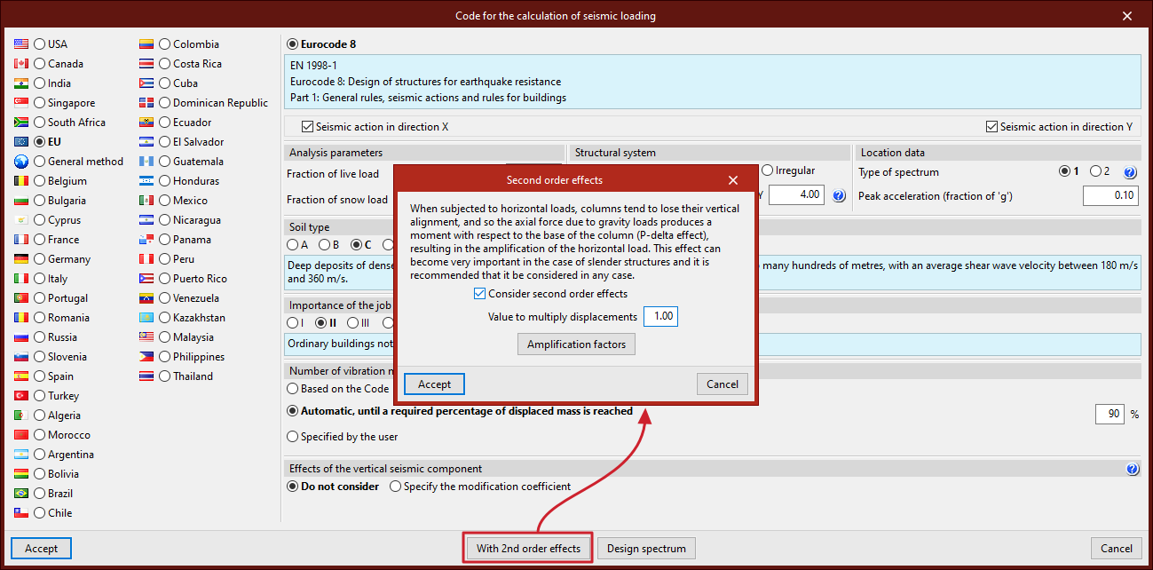
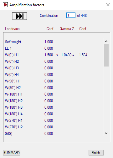
From the "Second order effects" window, you can also consult the "Amplification factors" of the horizontal actions from the most recent calculation.
For each loadcase in each combination, the unamplified and amplified magnification coefficients are shown, as well as the gamma Z value (which relates them).
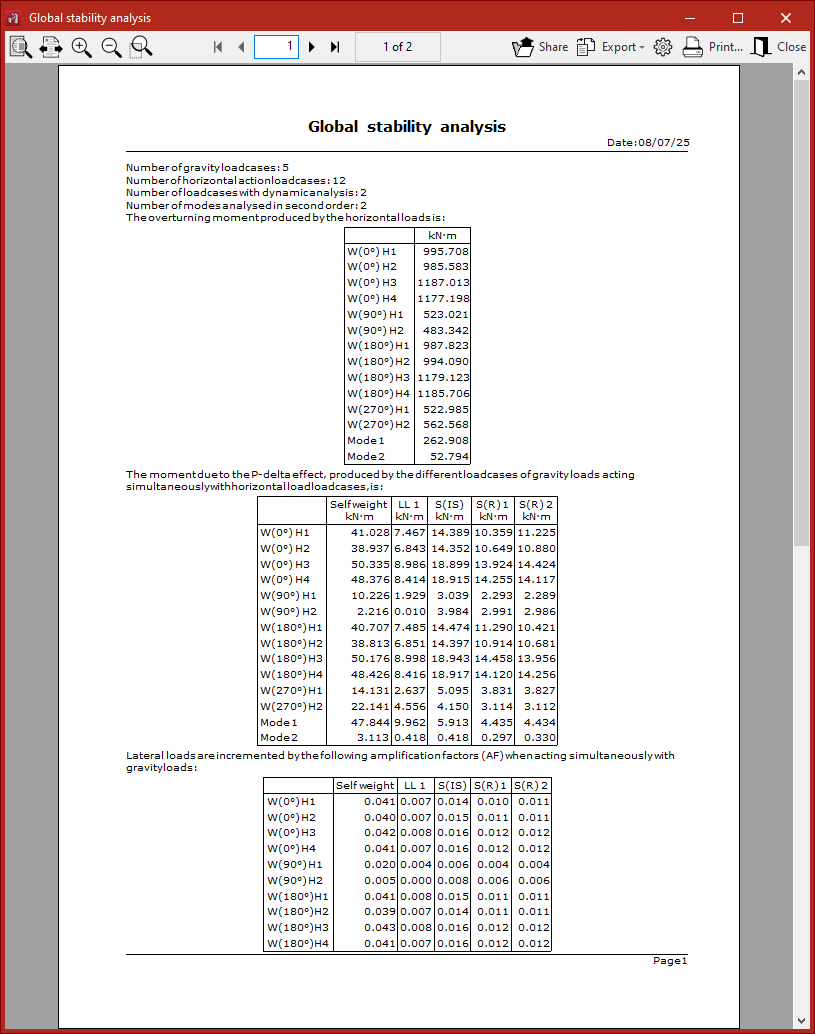
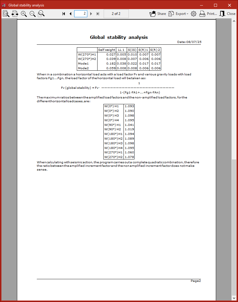
The bottom button allows you to access a summary report of the global stability analysis.
Once the seismic code configuration is complete, click "Accept" to return to the "General data" window.
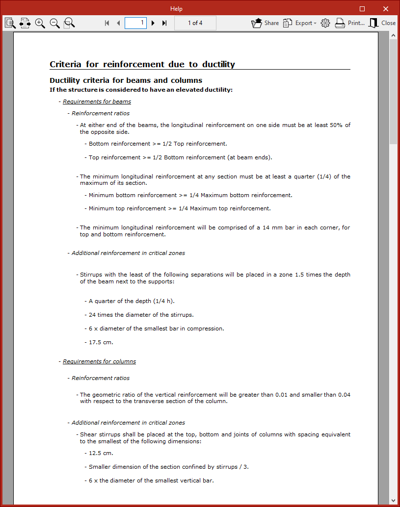
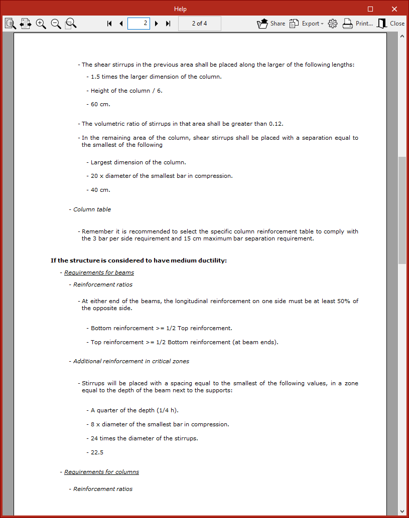
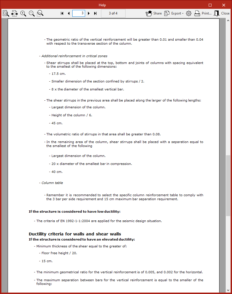
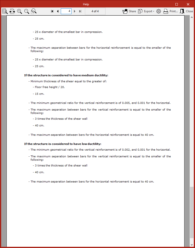
Reinforcement criteria by ductility
Once the seismic code has been configured, within the "Loads" section of the "General data" window, the "Criteria or reinforcement by ductility" can be defined for the design of concrete columns and beams, choosing between "Low ductility", "Medium ductility", or "High ductility".
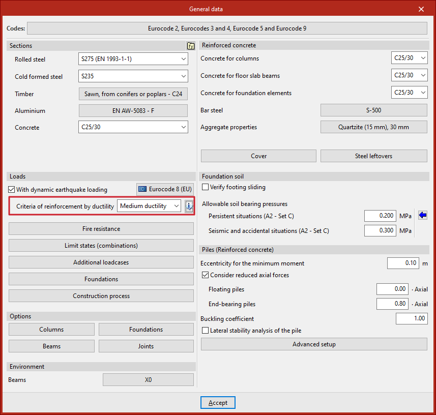
A detailed description of these criteria can be consulted via the help button.
Seismic analysis and report generation
By clicking "Accept" in the "General data" window, you return to the program’s main interface.
Once the model definition is complete, the structural analysis can be performed from the corresponding tab. The program performs a complete modal spectral analysis, solving each mode as a loadcase and carrying out modal expansion and combination to obtain internal forces.
After the model is analysed, the specific "Dynamic seismic loading" report can be consulted from the "Analysis" tab.