Geometry generation tools: planes, nodes and bars, and tetrahedral meshes
To automatically generate planes, nodes, bars and tetrahedral meshes in CYPE 3D, use the options in the "Generate" menu, which can be found in the "Tools" panel at the top of the interface, within the "Geometry" tab (under the "Structure" tab).

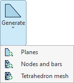
The options available in this menu are as follows:
- Plans
- Nodes and bars
- Tetrahedral meshes
Each of these features is described below.
Generating planes
The first option in the "Generate" menu, "Planes", allows you to generate planes parallel to a selected plane.
To do this, in a 3D view, left-click to select two reference lines contained within the plane you wish to copy.
Only planes perpendicular to a global reference axis can be generated.
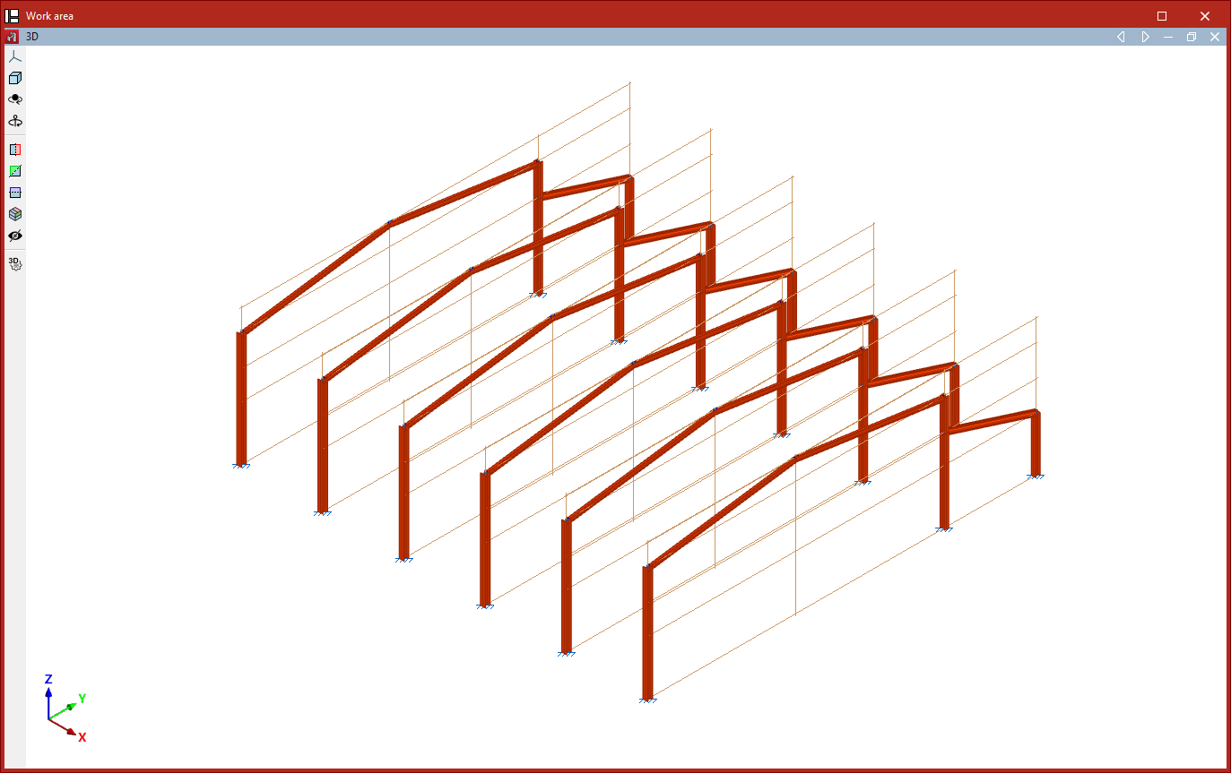
Next, in the "Plane generation" window, enter the "Number of planes to generate" and the "Separation between planes", and decide whether you want to "Group generated planes".
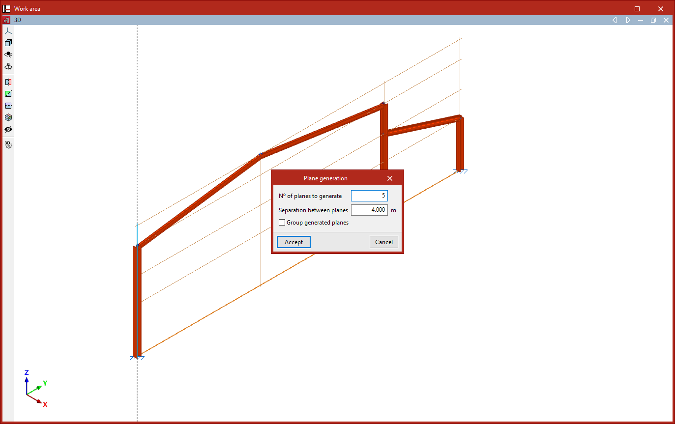
After clicking "Accept", the program generates the specified planes and copies the data entered into the original drawing, including nodes, bars, shells and loads.
Generating nodes and bars
The next option in the "Generate" menu, "Nodes and bars", allows you to generate nodes and bars by specifying the generation segments and the number of divisions per segment.
This generation can be linear if only one segment is selected, planar if two are selected, or spatial if three are selected.
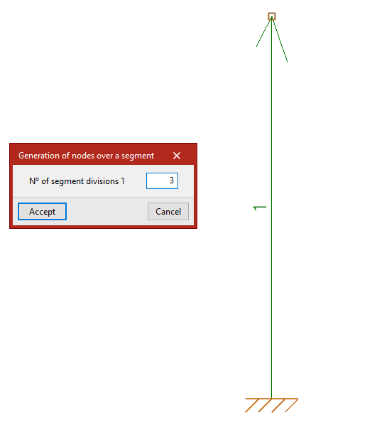
Generating nodes on a segment
To generate a linear series of nodes along a segment, first left-click on the start node and the end node of the segment you wish to divide into equal parts.
Next, right-click. The "Generate nodes on a segment" window will open, where you should enter the "Number of segment divisions".
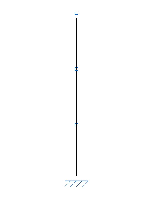
After clicking "Accept", vertices are created at the segment's division points.
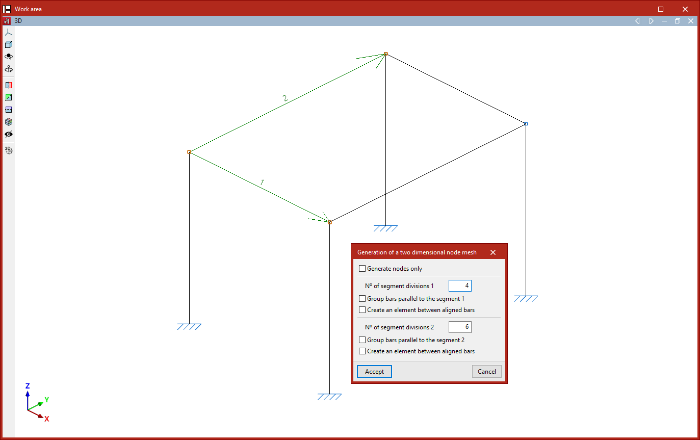
Generating a two-dimensional node mesh
To create a flat or two-dimensional drawing, after selecting the "Nodes and bars" option again, left-click on the start node and the end node of the first segment.
Next, to select the second segment, left-click on its end point. The segments do not need to be perpendicular to one another.
The program will number the segments as they are selected.
Right-clicking opens the "Generate a two-dimensional node mesh" window, which contains the following options:
- If desired, you can "Generate nodes only" by ticking the first box. This way, no beams are generated.
- The "Number of segment divisions" is shown below.
- It is also possible to "Group parallel bars" for each segment. This option automatically groups the bars generated parallel to the main segment, in exactly the same way as the "Group" option in the "Bar" menu.
- With the "Create an element between aligned bars" option, the bars forming the divisions within each segment will form a single part, in the same way as the "Part" option in the "Bars" group would.
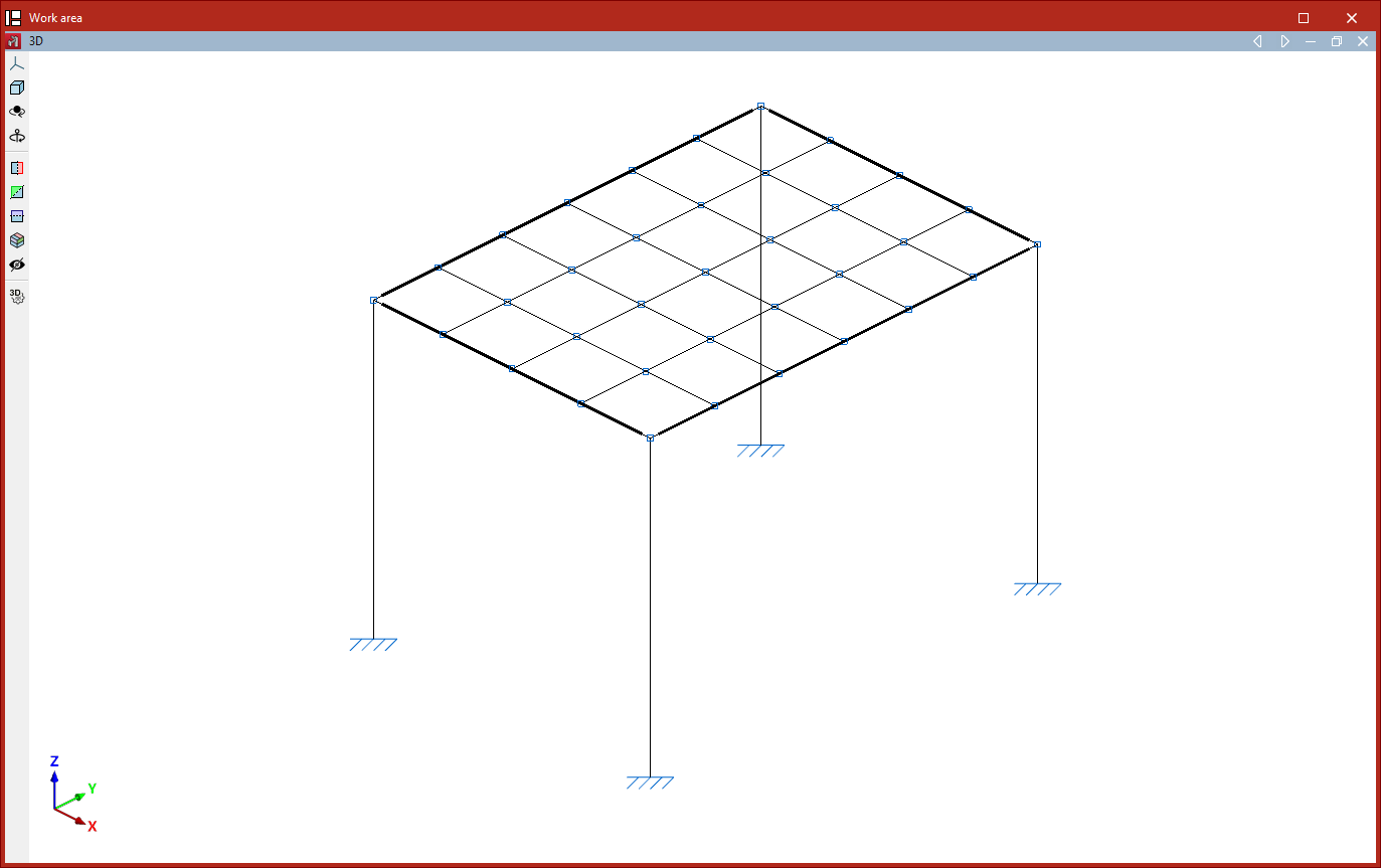
After clicking "Accept", a mesh of nodes is generated at the points where the segments meet. If specified, beams are also generated to connect these nodes.
Generating a three-dimensional mesh
Finally, the generation can be spatial. In this case, after selecting the "Nodes and bars" option, you must select three segments using the left mouse button.
First, left-click to select the start and end points of the first segment. Next, to select the second and third segments, simply left-click on their end points.
After right-clicking, the "Generation of a three dimensional node mesh" window appears. The options are identical to those described for generating 2D meshes. In this case, the divisions of the three segments are specified.
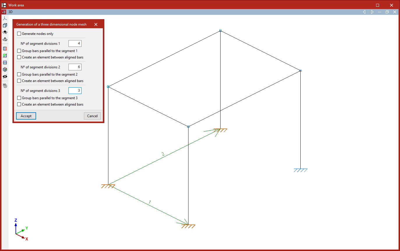
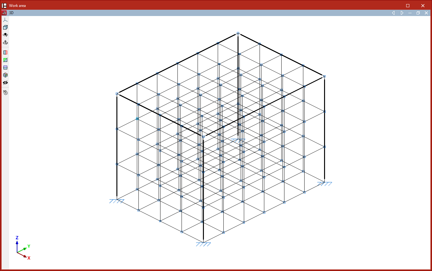
Clicking "Accept" results in a spatial mesh of nodes and bars connecting the division points of the specified segments.
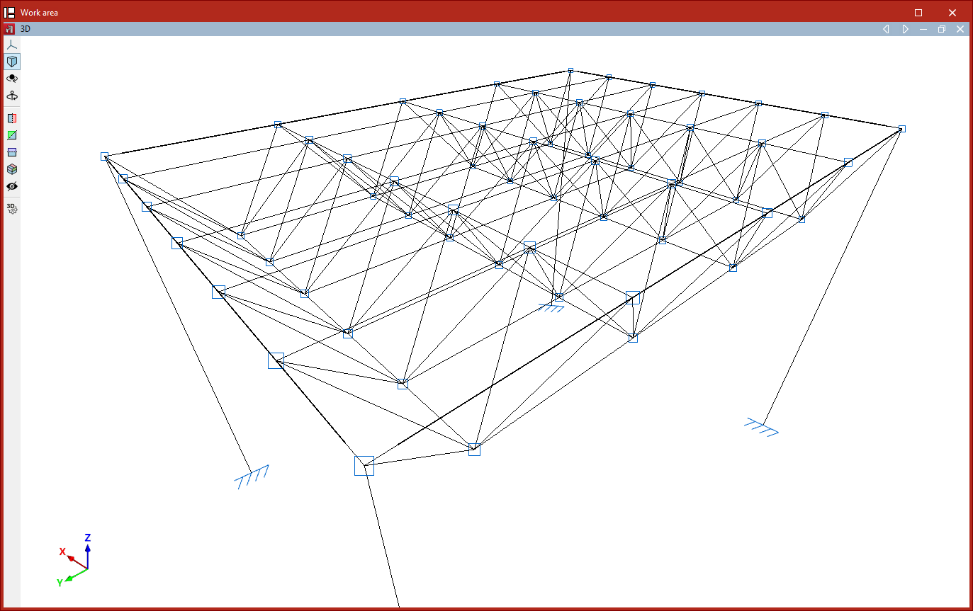
Generation of tetrahedral meshes
The "Tetrahedron mesh" option in the "Generate" menu allows you to generate a spatial tetrahedral mesh.
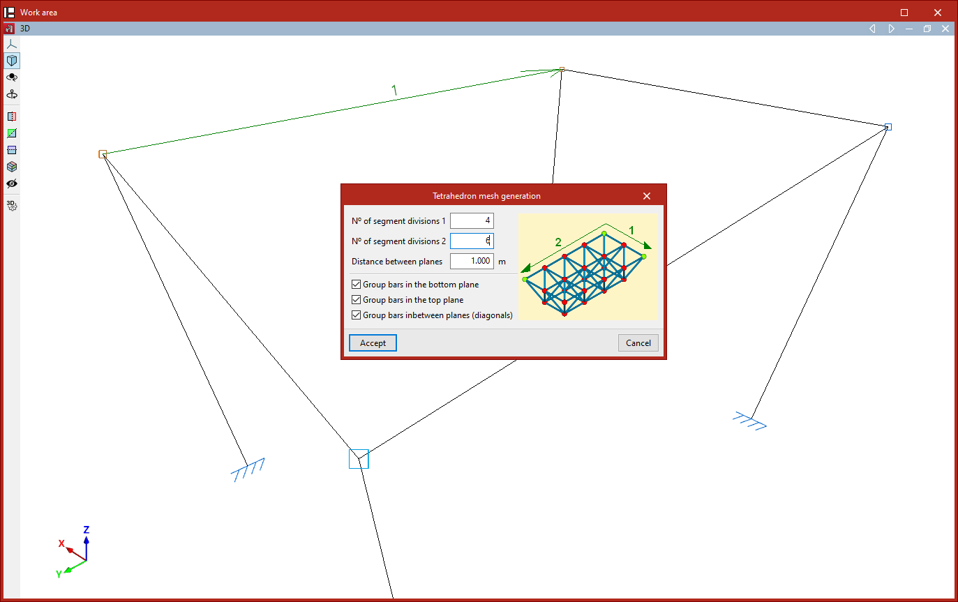
To do this, define two segments that form one of the mesh planes. Both segments share the same starting point. Click the left mouse button to select the start and end points of the first segment, and then the end point of the second segment.
This opens the "Generate a tetrahedron mesh" window, which contains the following options:
- Firstly, the "Number of divisions" is specified for each of the two segments, along with the "Distance between planes", which corresponds to the edge length of the generated tetrahedral mesh.
- There are then a number of options available for grouping the generated bars:
- Turning on "Group bars in the bottom plane" groups the bars contained within the plane formed by the two selected segments.
- The second checkbox, "Group bars on the top plane", allows you to group the bars contained in the plane parallel to the previous one.
- The last option allows you to "Group bars in between planes", i.e. the diagonal edges that make up the tetrahedral mesh.
After clicking "Accept", the program generates the tetrahedral mesh of nodes and bars.
The order in which the segments are selected determines the orientation of the tetrahedral mesh edge (upwards or downwards relative to the plane formed by the two segments).