Defining internal fixity in nodes
The internal fixity in the nodes of the structure is defined with the following option, available in the "Nodes" group of the top toolbar, in the "Properties" tab (in the "Structure" tab).

Internal fixity
Enters internal fixity. Internal fixities are those that relate the ends of the bars that are connected to the same node.
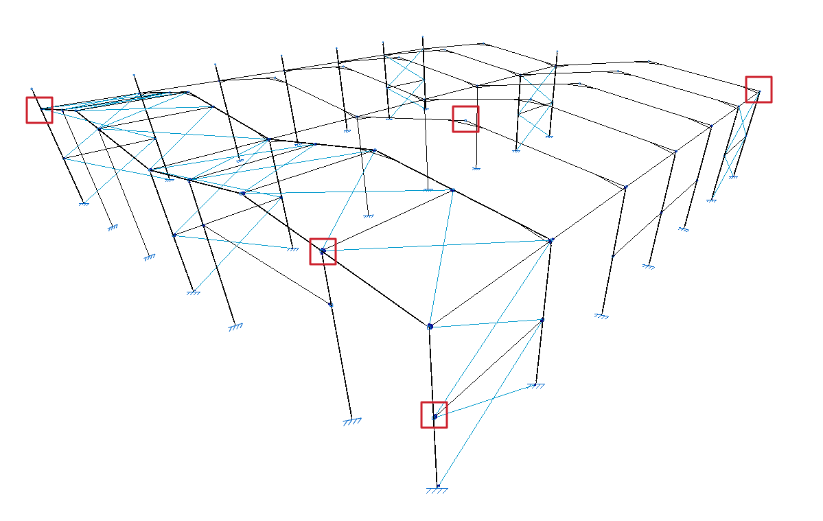
To do this, after clicking on the option, select the nodes where the fixity is to be defined one by one or draw a selection box that covers them with the left mouse button. Finally, click on the right mouse button.
The program then opens a window where users can choose the type of internal fixity from the following:
Fixed node
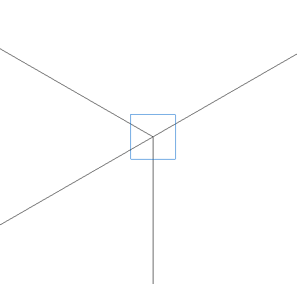
The "Fixed node" option defines a perfect fixity between all the bars that are connected to the node. As a result, they share the displacements and rotation angles in the design. This is the default option when entering new nodes or bars.
This is represented by a blue box symbol on the model display.
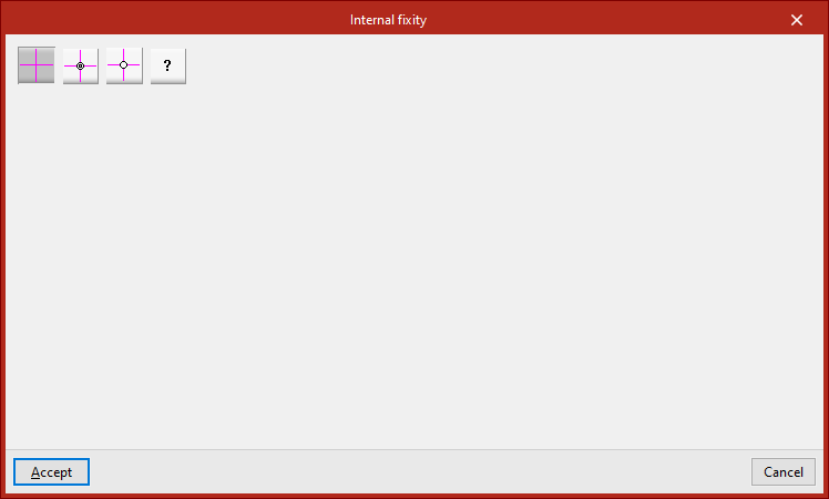
Fixed node with partial fixity coefficient for all its elements
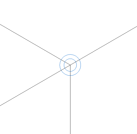
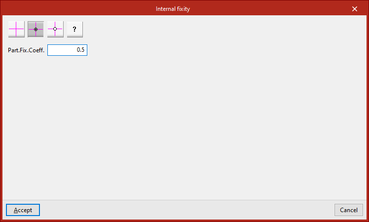
The "Fixed node with partial fixity coefficient for all its elements" option is used to enter the partial fixity coefficient ("Part.Fix.Coeff.") which defines the degree of recessing between the parts that reach the node. The value can be between 0, which corresponds to a pinned connection, and a very large value, which corresponds to a fixity.
This is represented by the symbol of a double blue circle in the model display.
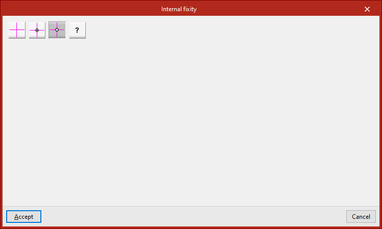
Pinned node
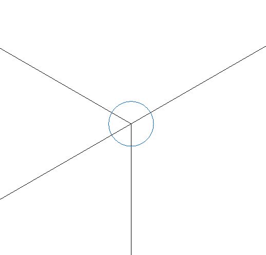
The "Pinned node" option defines a perfect link between all the elements that reach the node. In this case, the program uses a single blue circle above the node to represent the fixity.
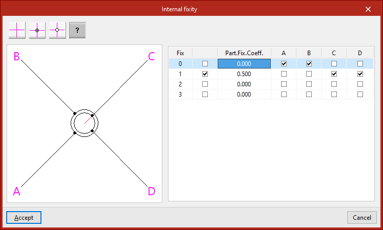
Generic node
The "Generic node" option is used to specify the degree of fixity between different groups of bars or shells that are attached to the node.
A diagram of the bars or shells is shown on the left. Each one is identified with the same reference letter as shown in the model display.
The table on the right describes the internal links between these elements. Each of the columns represents a bar or shell reaching the node and may have only one mark, which will be placed on one of the lines.
The bars or shells with the marking on the same line are embedded into each other and are linked with the rest of the bars or shells. In the diagram on the left, the elements embedded in each other are shown connected with the same circle.
If the box in the second column is activated, the elements with the same marking will be partially connected to the node. In this case, the value of the partial fixity coefficient ("Part.Fix.Coeff.") is written in the third column. This coefficient can take any positive value, with 0 corresponding to a joint.
If the box in the second column is unchecked, the program will not apply the defined partial embedding coefficient value.
In the diagram on the left, elements that are partially embedded are represented by a red line connecting them to the centre of the node.