Defining the internal fixity of shells
The definition of internal fixity on shell edges is carried out using the following option, available in the "Shells" group on the top toolbar, within the "Properties" tab (in the "Structure" section).

Internal fixity
The "Internal fixity" option allows you to edit the internal fixity of a group of edges.
Internal fixities define how the shell edges are connected to other adjacent elements present in the model, such as beams or other shells.
To do this, select the edges you wish to edit using the left mouse button or by drawing a selection box, then right-click.
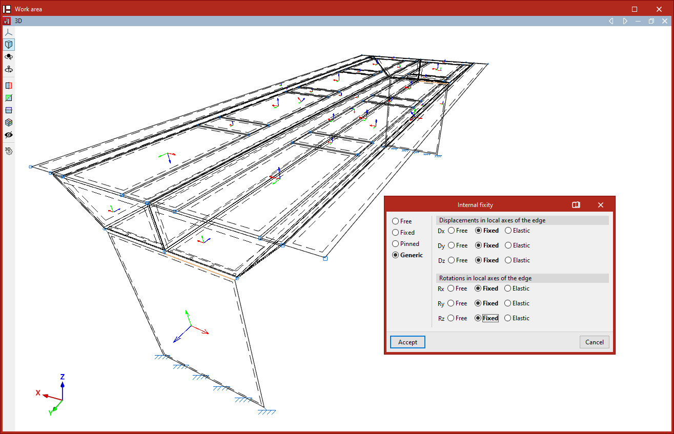
In the pop-up window, you can define whether the internal fixity is "Free", "Fixed", "Pinned", or "Generic". In the latter case, you can specify whether the "Displacements in the local axes of the edge" (Dx, Dy, and Dz) and the "Rotations in the local axes of the edge" (Rx, Ry, and Rz) are free, fixed, or elastic.
Then, click "Accept".
In the model view, the program represents each of these fixities differently.
The internal fixity defined in this way affects the internal nodes of the edge that are generated through the discretisation of the shells. To modify the internal fixity at the end nodes of the edge, you must use the "Internal fixity" option in the "Node" group.