Editing the lateral buckling parameters of the bars
The lateral buckling parameters for the bars are defined using the following option, which is available in the "Bars" group on the top toolbar, within the "Properties" tab (under the "Structure" section).

Lateral buckling
The "Lateral buckling" option allows you to edit the parameters relating to the lateral buckling of the bars.
After clicking on the option, select each bar by clicking on them one by one, or highlight a capture area. Then, right-click.
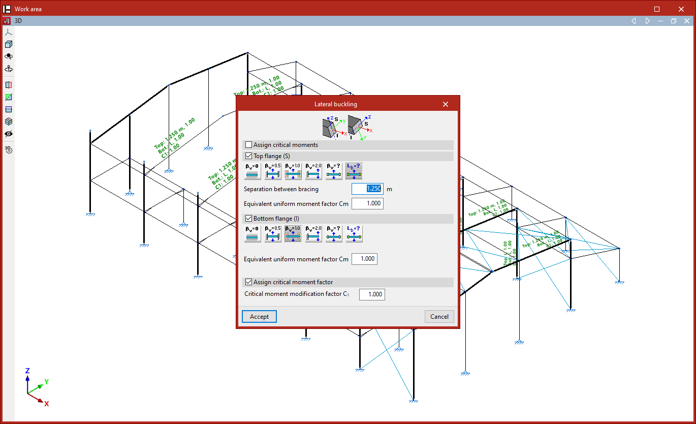
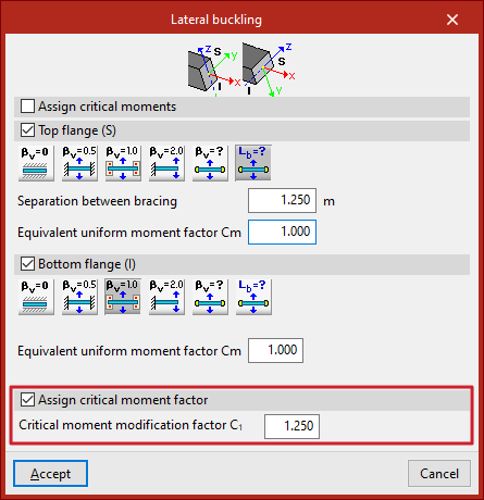
In the window that appears, you can define the lateral buckling parameters in two different ways:
- If the "Assign critical moments" checkbox remains unchecked, the lateral buckling lengths (or lateral buckling coefficients) of the bar must be entered, along with the modification factor for the critical moment. In this case, the critical moments of the bar are calculated automatically by the program.
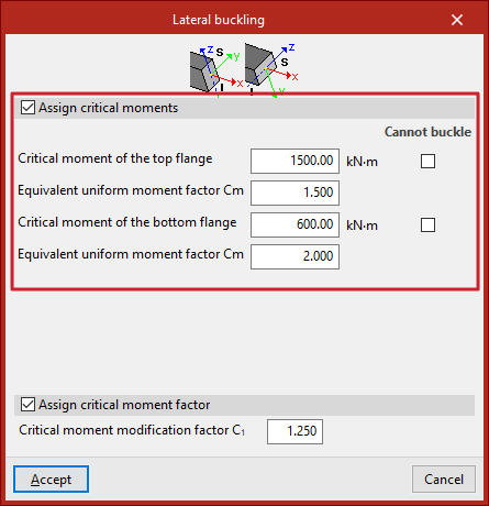
- If the "Assign critical moments" checkbox is checked, you can enter the values for the critical lateral buckling moments, and the modification factor for the critical moment.
The diagram above shows the positions of the upper and lower flanges of the section in relation to the orientation of the local coordinate axes, using the same colour coding as in the model.
Assignment of critical moments
If you choose to assign critical moments, tick the "Assign critical moments" box.
This section, available for rolled and formed steel bars, allows you to manually enter the values of the critical lateral buckling moments as an alternative to the lateral buckling lengths:
- Critical moment for the top flange
- Equivalent uniform moment factor Cm (for the top flange)
- A critical moment of the bottom flange
- Equivalent uniform moment factor Cm (for the bottom flange)
The "Cannot buckle" checkbox can be selected for any flange. In this case, an infinite critical moment is assumed.
The "Assign critical moment factor" option is available for the following standards:
- Eurocodes 3 and 4
Assignment of lateral buckling lengths or lateral buckling coefficients
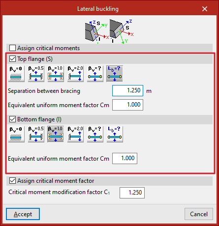
If you choose to assign lateral buckling lengths or lateral buckling coefficients, the "Assign critical moments" checkbox is deselected.
You can then define the lateral buckling parameters for the "upper flange" and "lower flange" of the section by ticking the relevant boxes.
If you choose to define the lateral buckling coefficient, this value will be multiplied by the length of the bar from joint to joint to obtain the lateral buckling length, or the spacing between bracing bars.
The options available in each flange include the following:
- Does not check for lateral
buckling. In this case, the program uses a predefined value for the lateral buckling coefficient, set to 0. This is the default value. Consequently, the program does not take lateral buckling into account. - Well-braced beam
A lateral buckling coefficient of 0.5 is assumed. - Self-supported beam
A lateral buckling coefficient of 1 is assumed. - Cantilever beam
A lateral buckling coefficient of 2 is assumed. - Lateral buckling coefficient
This allows you to enter the value of the lateral buckling coefficient manually instead of using one of the predefined values. To do this, enter the value in the field below. - Spacing between bracing bars
This allows you to enter the spacing between bracing bars or the lateral buckling length of each flange directly, rather than using a coefficient. To do this, select the relevant option and enter the value in the units of measurement defined in the project.
In addition, the program allows you to enter the "Equivalent moment coefficient" for each of the flanges.
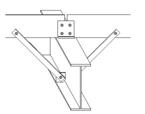
The installation of flange fasteners, such as these struts, allows for a lower lateral buckling coefficient or bracing spacing to be used. For example, if these elements are positioned at the midpoint of the section’s length, it may be justified to use a lateral buckling coefficient of 0.5.
Assignment of the modification factor for the critical moment
Finally, you can tick the "Assign critical moment factor" box to enter the "Modification factor for the critical moment".
Each standard provides values for the equivalent moment coefficients and for the critical moment adjustment factor based on the different bending moment distributions in the bars between bracing points.
By default, the program uses coefficients equal to one.
Results
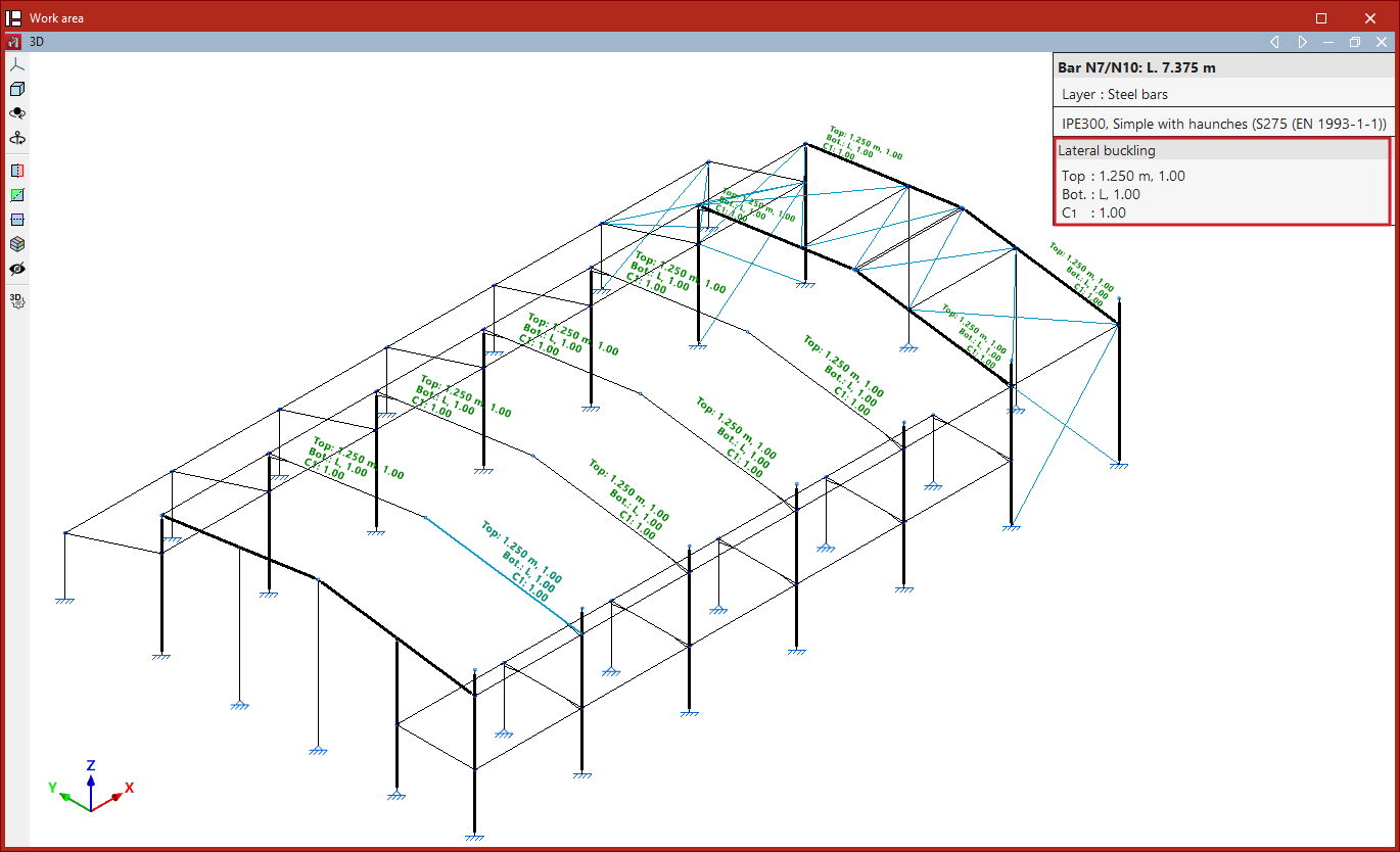
Finally, click "Accept". When you hover over the bars, the program displays text above them showing the values of the parameters applied to the two flanges and the value of the critical moment factor.
This information is also displayed in the pop-up box that appears when you hover the cursor over the bars, under the "Lateral buckling" section.
If no lateral buckling parameters have been assigned to the bars when clicking "Analyse", the program displays a "Warning" message to this effect. If you continue, the default values will be used.
| Note: |
|---|
| Lateral buckling parameters have a significant impact on certain bar checks. These checks vary depending on the selected code and can be found in the "U.L.S checks" reports under the "Analysis" menu. Among these, the "Y-axis bending resistance" check is worth mentioning. |