Load visualisation options
The options for editing the visualisation of load cases and adjusting their scale are available in the "View" group on the top toolbar, within the "Load" tab (under the "Structure" section).

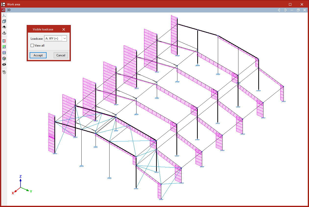
Visible load case
The "Visible load case" option allows you to select which load case to display. In the pop-up window, choose the active "Load case" from the dropdown menu, then click "Accept".
The loads assigned to the selected case will then be shown in the model viewer. For each load, the program displays its direction of application and value in the selected units.
For surface loads and loads on panels, the program will display the resulting line loads on the bars after distribution.
From this point on, any new loads inserted will, by default, be assigned to the selected load case.
If you access the same option again, you will see that it is also possible to activate the "View all" checkbox. When enabled, the model will display the loads assigned to all load cases, each shown in a different colour.
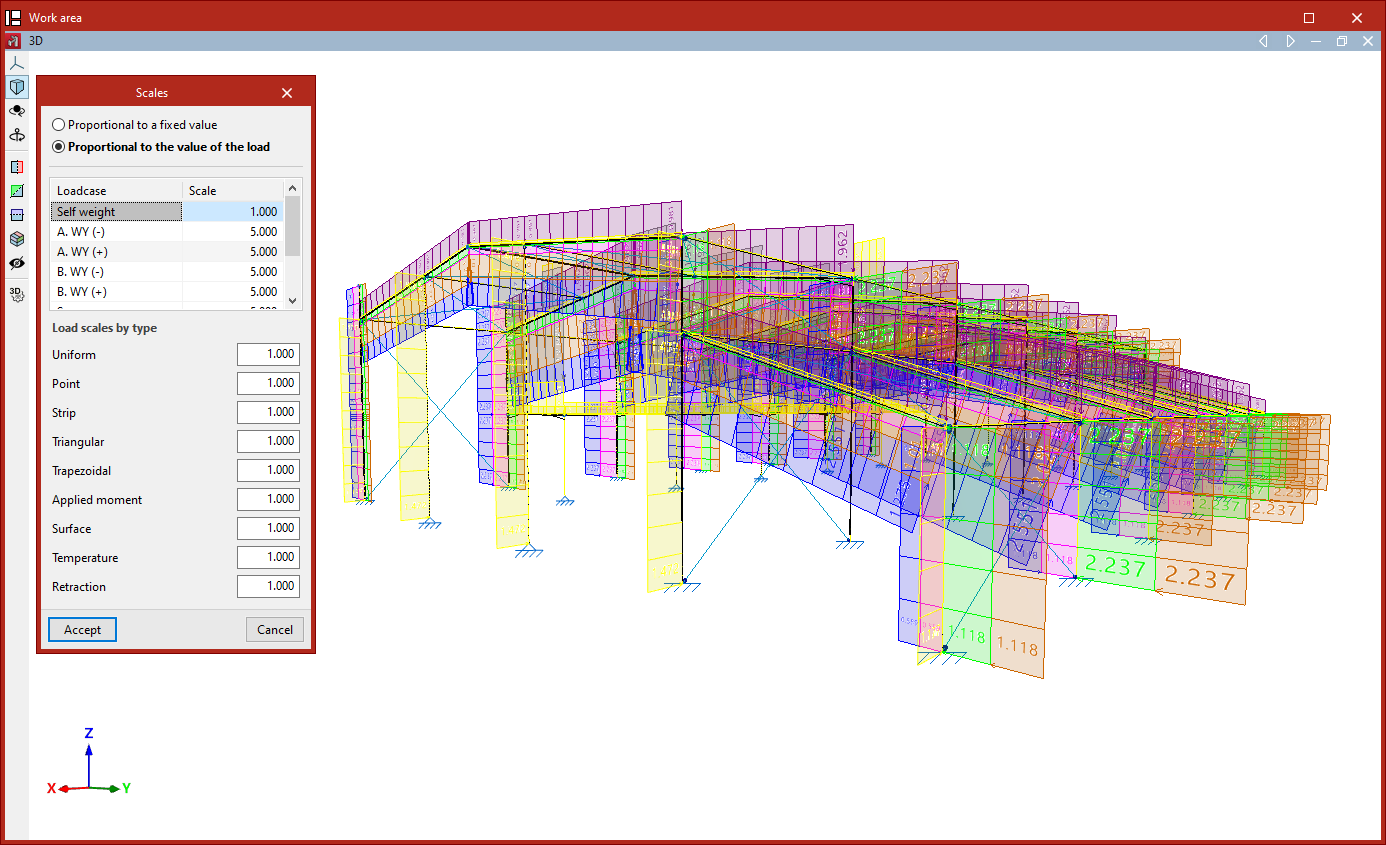
Scale
The "Scale" option allows you to adjust the drawing scale for load representations.
First, you can choose between "Proportional to a fixed value", in which case you specify the "Maximum representation size", or "Proportional to the load value".
If you select the latter, and you wish to edit the scale for each defined "Load case", you can input the scale factor for each case in the central table.
You can also specify "Load scale by type" values, which apply to the following load types:
"Uniform", "Point", "Strip", "Triangular", "Trapezoidal", "Applied moment", "Surface", Temperature", and "Retraction".
These values act as multipliers to the previously defined scale values.Finally, click "Accept" to apply the changes and adjust the size of the load representations in the viewer.