Configuring pile cap options
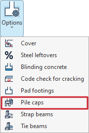
The settings for the pile caps are available by selecting "Pile caps" from the "Options" menu in the "Project" section at the top of the interface, under the "Foundations" tab.

Clicking on this option opens the "Pile caps" window, which contains the following tabs:
- General
- Single pile
- Pile cap beams
- Beams and meshes
- Reinforcement
Each of these is detailed below.
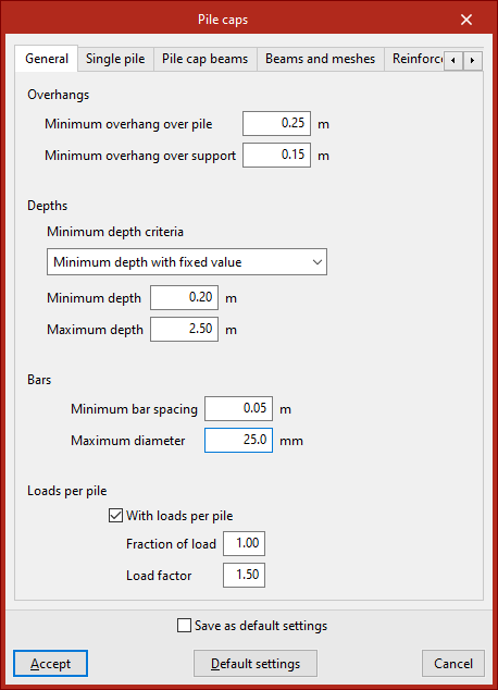
"General" tab
The "General" tab is used to set a series of criteria for the design and verification of pile caps.
Firstly, the minimum “Overhangs” for the pile cap are defined, including the “Minimum overhang over the pile” and the “Minimum overhang over the support”.
Next, in the "Bars" section, select the "Minimum depth criteria". This can be a "Minimum depth with fixed value", in which case you must enter the value in the field below, or a minimum edge based on various standards (such as EH-91, EHE or NB-1). Further down, define the "Maximum edge" of the grid.
When configuring the "Bars", you need to enter the "Minimum bar spacing" and their "Maximum diameter".
"Loads per pile" option
The "Loads per pile" option should be selected in cases where you wish to standardise the design of pile caps for a specific number of piles, even though the loads on the supports differ.
When this option is selected, the program generates a new design combination for the pile cap, assuming that the maximum load on the pile is equal to the pile’s bearing capacity (the maximum load it can withstand without failure) multiplied by the “Load safety factor” and the “Load factor” (between 0 and 1) entered in the fields below. The load fraction allows the load to be reduced if the installed pile withstands much more than it theoretically needs to bear, i.e. if it is oversized.
Normally, this combination ensures that all pile caps of the same type (same number of piles and geometry) are constructed in the same way, as it is usually the least favourable combination when using the default values, thereby simplifying the construction process.
| Note: |
|---|
| Nd = Cp × Gp × Fp, where Nd: design bearing capacity of the pile Cp: bearing capacity of the pile Gp: load safety factor Fp: load fraction |
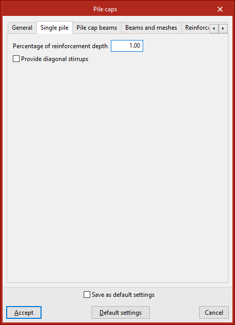
"Single pile" tab
The "Single pile" tab is used to set options for analysing the pile foundations.
The "Percentage of reinforcement depth" is the percentage of the reinforcement web depth that is intended to absorb the tensile forces arising in a concrete mass due to divergence in the compression struts. This value is used in the design to determine the effective depth of the reinforcement web.
Enabling the following option allows you to "Provide diagonal stirrups", which helps to confine the concrete in the slab. This layout is recommended where significant live loads are present.
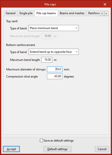
"Pile cap beams" tab
The "Pile cap beams" tab is used to define the settings required for the design of beams embedded within another beam.
Under "Type of bend", select the criteria for sizing the stirrups in the bars that make up both the "Top reinforcement" and the "Bottom reinforcement" of the beam ends:
- Extend bend up to opposite face
The bends extend to the face of the opposite wall. In this case, the "Maximum bend length" must be specified. - Place minimum bend
Bends are fitted to the minimum length necessary to ensure secure anchoring.
The "Maximum diameter of the stirrups" for the formwork beams and the "Compression strut angle" (between 30 and 60 degrees) are also specified.
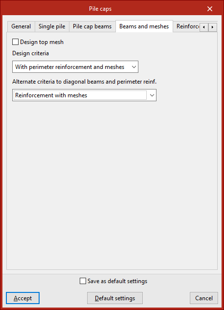
"Beams and meshes" tab
This tab allows you to specify the reinforcement layout used in the pile caps used during the design process.
Select the reinforcement layout from the following options:
- Reinforcement according to EHE code
The pile caps are assembled using side beams and meshes (in accordance with the EHE-98 standard). - Reinforcement with meshes
The pile caps are reinforced using meshes only. - Reinforcement with diagonal beams (*)
Pile caps are reinforced using side beams and middle or diagonal beams. - With perimeter reinforcement and mesh panels (*)
The pile caps are reinforced using perimeter reinforcement and mesh panels. - With perimeter reinforcement and meshes (*)
The pile caps are reinforced using perimeter reinforcement and central or diagonal beams.
For all standards, the reinforcement layout specified in the reference standard will be accepted as correct during verification; consequently, some verification results may not comply with assembly configurations other than those specified in this standard.
(*) In the case of pile caps that do not accommodate central or diagonal beams, an “Alternative approach to diagonal beams and perimeter reinforcement” must be specified. Thus, the design may be carried out in accordance with the provisions of the reference standard (“Reinforcement according to EHE code”) or by replacing the diagonal beams with meshes (“Reinforcement with truss grids”). In rectangular pile caps, all the tensile reinforcement cannot be arranged around the perimeter of the frame, as this would require a very large depth; therefore, for this type of frame, if the design is carried out using perimeter reinforcement, it is also necessary to choose one of the two alternative criteria.
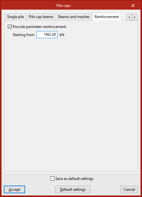
"Reinforcement" tab
In this tab, you can select the "Provide perimeter reinforcement" option to improve the confinement of the concrete in the pile cap. It is advisable to enable this option if the pile cap is subject to significant structural loads.
The load specified in the "Starting from" field refers to increased loads for the ultimate limit states of concrete. Perimeter reinforcement shall be provided when the design axial force is equal to or greater than the value entered in this field.