

Plastic hinges under axial force
The program expands its non-linear analysis capabilities by incorporating the definition of plastic hinges under axial force, with "Force - displacement" behaviour in the longitudinal (axial) degree of freedom of the bar. This feature complements traditional moment-rotation hinges, enabling highly realistic modelling of section failure due to plasticisation caused by tension or buckling caused by excessive compression.
Key applications
Although their primary application is in the bracing of portal frames (CBF and BRB) to simulate energy dissipation through tensile creep and post-buckling degradation under compression, these axial hinges are essential in other structural elements:
- Main trusses and lattice structures
In long-span structures, bridges and transfer structures where the chords and diagonal bars behave as pin-jointed elements and may fail in tension or buckle under extreme loading conditions. - Cables, tensioners and tie rods
Elements requiring specific non-linear axial laws, accounting for tensile failure or yielding and the complete loss of stiffness under compression.
Plastic hinge library and types of behaviour
The "Plastic hinge library", accessible via the "Project" tab (in the "Structure" section), allows you to create new entries under the "Force – displacement" category, offering three main behaviour options in the "Type" drop-down menu:
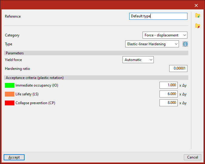
Elastic-linear Hardening
Model linear behaviour with a configurable hardening ratio.
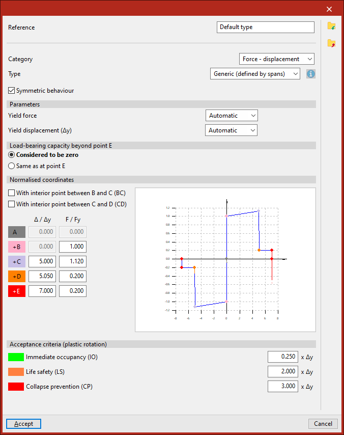
Generic (defined by spans)
Define custom curves or adopt the OpenSees’ Hysteretic SM behaviour, specifying normalised coordinates and acceptance criteria (immediate occupancy, life safety and collapse prevention).
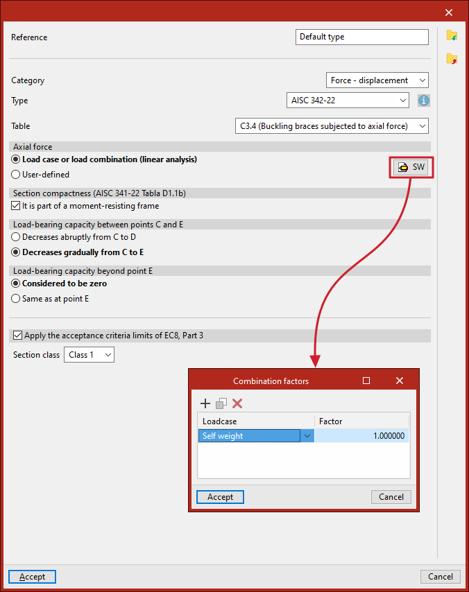
ASCE Standard 342-22
Designed specifically for buckling braces, it automatically calculates the expected resistances using the expected elastic limit (fye = Ry · fy) and omitting the partial safety factors (φ = 1.0), accurately reflecting the degradation curve and the asymmetric behaviour under compression and tension.
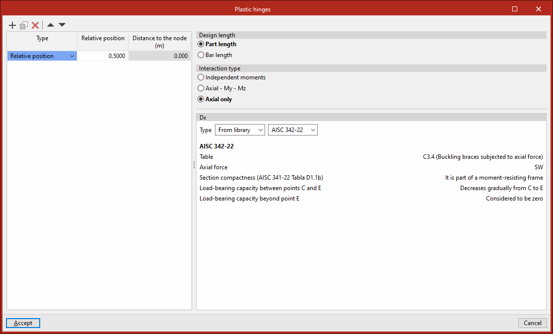
Allocation, positioning and analysis
Using the "Plastic hinges" option in the "Bar" menu on the "Properties" tab (under the "Structure" tab), you can select the elements and position the hinge along their length (they are usually positioned halfway along the bar). Once defined, the program lets you run the various types of non-linear analysis, taking these new hinges into account.
In the case of a pushover analysis, in exactly the same way as for moment-rotation hinges, you can view the results and assess the structural performance.
Performance curve of the plastic hinges under axial force
The backbone curve (or skeleton curve) defining the behaviour of a purely axial plastic hinge (force versus displacement) has one fundamental characteristic: it is markedly asymmetric, reflecting the differences in the response of the material and the structure under tension and compression.
Based on standards such as ASCE 41 / AISC 342 and the principles of structural mechanics, this curve is typically modelled using a multilinear model characterised by the following key points:
- Expected strengths (Point B):
Unlike conventional design, the curve is not based on nominal values, but on the expected strengths using the expected yield strength of the material (fye = Ry · fy) and assuming unit safety factors (φ = 1.0).- In tension
The material reaches its expected yield capacity (TCE = Ag·Ry·fy), potentially developing a stable plastic strain-hardening branch. - In compression
This is calculated using the buckling formulas for bars (such as those in the AISC or Eurocode), replacing the expected yield strength to determine the compressive buckling load (PCE).
- In tension
- Degradation and post-buckling branch (Compression):
While under tension, the element maintains a prolonged ductile plateau (points C, D and E with a high deformation capacity), the compression quadrant is characterised by severe geometric instability. After reaching the peak compressive load (PCE, coinciding almost exactly with point C), there is a sharp drop or negative slope (section C–D) which reflects the sudden loss of stiffness and strength as the element bends out of its plane. - Residual resistance and ultimate failure (Points D and E):
Following the collapse, the force stabilises at a residual plateau (point D), the value of which is usually between 20 per cent and 40 per cent of the initial buckling capacity, depending directly on the compactness of the cross-section. Finally, point E marks the ultimate deformation under compression, beyond which the element’s axial load-bearing capacity is considered to be zero.
This asymmetric behaviour is the standard approach for modelling energy dissipation in elements such as conventional buckling bracing (CBF), where the alternation between ductile tension and compressive buckling defines the structure’s seismic response.