Fire resistance settings (the "Properties" tab)
To configure the fire resistance of specific bars, select the "Fire resistance" menu from the "Bars" section at the top of the "Properties" tab interface.

The options in this menu will be available if you have previously enabled the fire resistance check in the "General data" section of the "Project" tab.
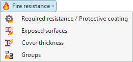
The options available in this menu are as follows:
- Required resistance / Protective coating
- Exposed surfaces
- Cover thickness
- Groups
Each of these features is described below:
Required resistance / Protective coating
The "Required resistance / Protective coating" option allows you to define specific settings for testing the fire resistance of a selection of bars.
After clicking on the option, select the bars one by one using the left mouse button, or highlight a capture area and click the right mouse button.
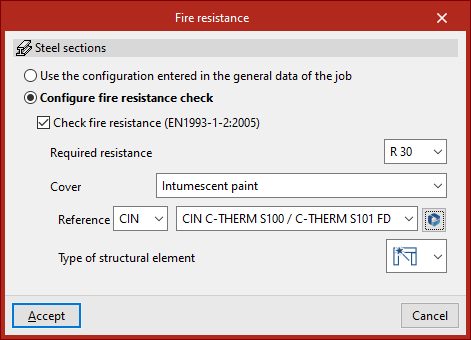
The "Fire resistance" window then appears. Here, the program displays the type of member selected – in this case, "Steel sections" – and allows you to either "Use the configuration entered in the general data of the job" or "Configure the fire resistance check" specifically.
If the second option is selected, the same options available in the "Fire resistance" settings under "General data" will appear; however, in this case, once "Accept" is clicked, they will apply only to the selected bars.
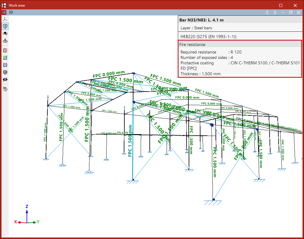
Using this option, you can also hover the cursor over the bars to display an information box specifying the defined "Fire resistance" and, where applicable, the type of protective cladding.
Exposed surfaces
The "Exposed surfaces" option allows you to specify which surfaces of the bars are exposed to fire. This enables you to optimise the thickness of the protective coating, as well as the cross-sections of the bars, where the surfaces of the bars are not exposed to fire.
Definition of exposed surfaces in steel sections
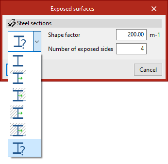
In the "Exposed surfaces" window that appears after selecting the sections, you must select one of the following options from the drop-down menu to define the section’s exposure.
In the first option, the program automatically calculates the shape factor based on the exposed surfaces:
- Section with all four exposed sides
- Section with three exposed sides (side and bottom)
- Section with two exposed sides (right side and bottom)
- Section with exposed sides (left side and bottom)
- Section with one exposed sides (bottom)
By default, and as a conservative approach, the program assumes a section with four exposed faces.
In the last option, the user manually enters the "Shape factor" and the "Number of exposed sides" (between 1 and 4).
| Note: |
|---|
| The program displays the local Y-axis of the section in green on the symbol for each type of exposure, to identify the position and orientation of the exposed surfaces relative to it. |
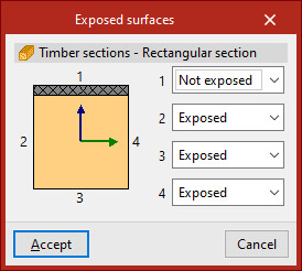
Defining exposed surfaces on timber bars
For timber beams with a rectangular cross-section, you can specify for each of the four surfaces of the cross-section whether it is "Exposed" to fire or "Not exposed".
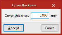
Cover thickness
The "Cover thickness" option allows you to enter the thickness of the fire-retardant coating applied to the selected bars directly.
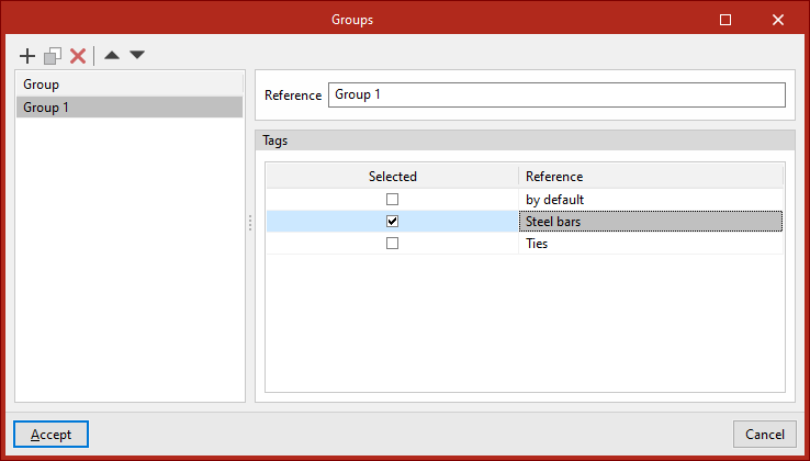
Groups
The program can deisng the thicknesses of fire-resistant cladding. The design can be carried out by setting the thickness of bars belonging to the same group to the same value, among other options. The "Groups" option allows you to create design groups, which can consist of bars assigned to one or more labels.
You must enter a "Reference" for each group and, by ticking the relevant boxes, select the "Labels" assigned to the elements you wish to include in each group.