Configuring foundation reinforcement tables
The reinforcement tables for foundation elements are configured using the options in the "Reinforcement tables" menu within the "Structure" section at the top of the interface, under the "Foundations" tab.

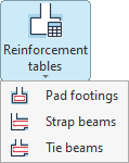
From this menu, you can configure:
- the reinforcement tabless for the insulated footings,
- the reinforcement tables for strap beams,
- and the reinforcement tables for the tie beams.
Each of these options is described below.
Reinforcement tables for pad footings
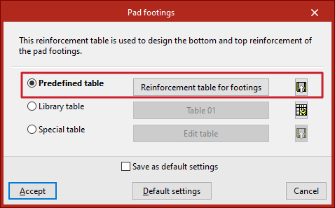
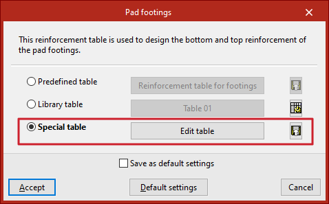
Click on the first option to configure the tables for "Pad footings". These tables are used to dimension the lower and upper reinforcement for these elements. Here, you can use the predefined or default table, one of the tables from the library, or a table specific to the project.
Predefined table
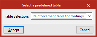
Tick the "Predefined table" box if you wish to use the program's default table in the analysis. To do this, click the middle button and select it from the drop-down menu. This table cannot be deleted or edited.
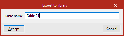
By clicking the button on the far right, you can "Export the reinforcement table to the library", then enter the "Table name". Library tables can be used in other projects.
Library table
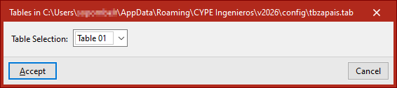
You can use any of the available library tables by ticking the "Library table" option and selecting it from the drop-down menu that appears when you click the centre button. This menu displays the reinforcement tables exported from the other options, as well as tables created from scratch via the library table editor. At the top, the program displays the file path where the tables are saved.
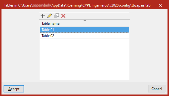
If you wish to "Edit the library tables", click the button on the right. This will take you to the list of assembly tables. You can "Add", "Edit", "Copy" or "Delete" any of them.
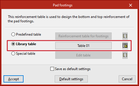
Special table
The "Special table" option allows you to use a custom reinforcement table for the current project. When you select this option, the table that was previously selected is duplicated.
You can then edit the data in the table by clicking on "Edit table".
Using the button on the far right, you can "Export the custom table to the library" by clicking the button on the right and then entering the "Table name".
Editing reinforcement tables for isolated footings
When editing a reinforcement schedule for isolated footings – whether a library table or a site-specific table – the program displays a series of reinforcement “Diameter(s)”, along with their “Spacing”, and the “Minimum depth” and “Maximum depth” of the elements where each entry can be applied. Any of these parameters can be modified by clicking on the relevant cell.
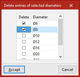
At the top, there are tools to "Add", "Copy" or "Delete" table entries, as well as "Delete selected diameter entries".
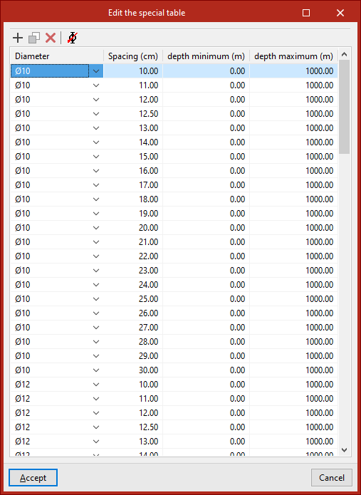
Finally, click "Accept" to use the selected table and confirm the changes.
Assembly diagrams for strap beams and tie beams
The operation of the reinforcement tables for "Strap beams" and "Tie beams" is very similar and offers the same options as the reinforcement tables for isolated footings; you can also use predefined, library or special tables.
Editing reinforcement tables for strap beams and tie beams
The reinforcement tables for strap beams and tie beams are used to determine the dimensions of the beam cross-sections, as well as the reinforcement layout.
Therefore, if you use the "Edit table" option, you will see that each entry in the table, identified by a "Reference", corresponds to a beam of a specific "Width" and "Depth".
You can change these values by clicking on each cell.
In the viewport to the right of the table, the program displays the dimensions and assembly of the selected entry.
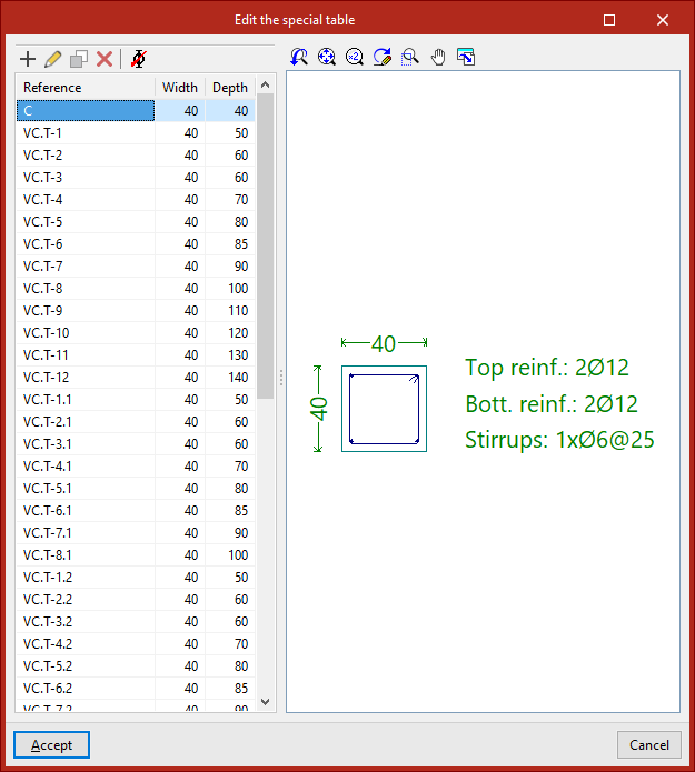
To edit the layout associated with each entry in the table, use the "Edit" button at the top.
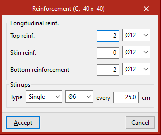
It is possible to modify both the "Longitudinal reinforcement" – whether the "Top reinforcement", "Skin reinforcement" or "Bottom reinforcement" – and the "Stirrups" of the beam, including their "Type", diameter and spacing.
Finally, click "Accept" to apply the changes.