Defining special aluminium sections
The program allows the use of special aluminium sections and lets you freely define their geometry by entering straight segments, curved segments, and elements with stiffeners through the following options.

Accessing the definition of special aluminium sections
Special aluminium sections are entered and edited using the "Section" option, available in the "Bars" group of the top toolbar, within the "Geometry" tab (on the "Structure" sheet).
Then, individual bars are selected using the left mouse button or by drawing a selection window. Right-clicking opens the "Describe" window.
This window can also be accessed when entering a new bar by clicking the edit button in the "Properties – New bar"window.
Here, the following options are selected:
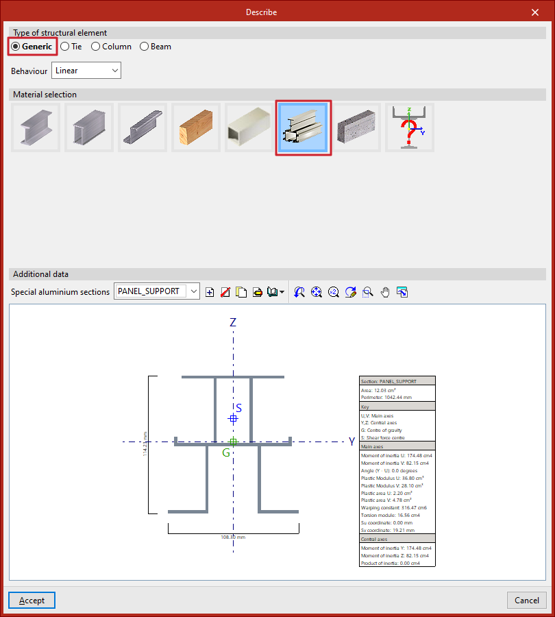
- In the "Type of structural element" section, a "Generic" element is defined
- Then, in the "Material selection" section, "Special aluminium sections" is selected
Special aluminium sections library
After selecting the indicated options, the program displays the "Additional data" of the section in the lower part of the "Describe" window. By default, the "Special aluminium sections" dropdown will be empty. On the right, you’ll find tools to "Create", "Delete", "Copy", and "Edit" sections.
From "Library management", you can "Import from library", "Export" to use in another project, "Edit the library", or define an "Initial import" for all projects.
Clicking on "Create", "Copy", or "Edit" opens the special aluminium section editor.
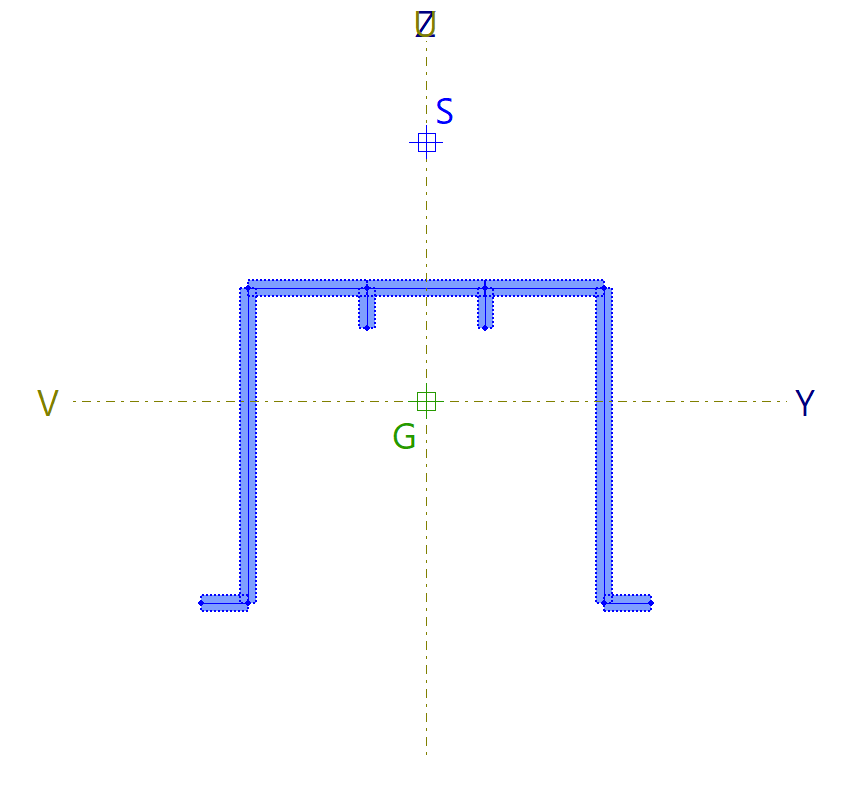
When a specific special aluminium section is defined and selected, the viewer at the bottom displays the drawn section, showing total width and height, the location of principal (U, V) and central (Y, Z) axes, the centre of gravity (G), and the shear centre (S). A table on the right shows the main characteristics of the section.
Special aluminium section editor
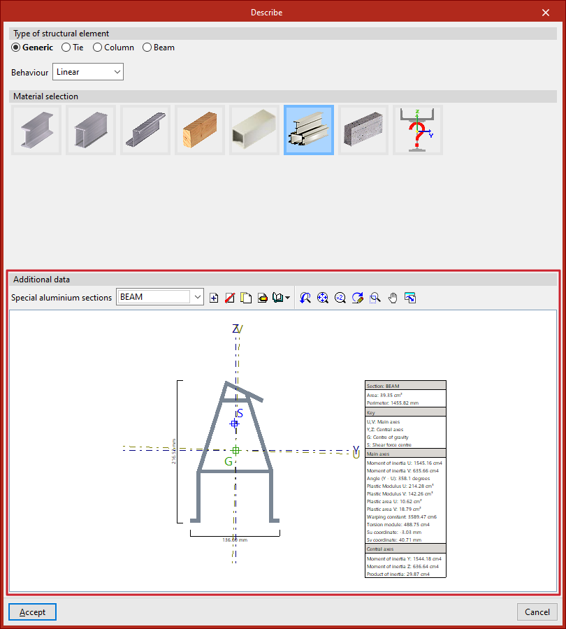
In the special aluminium section editor, the first step is to enter a "Reference" for the section.
Below that, in the central viewer, the section is drawn. This viewer offers:
- options to enter the segments that make up the section in the top left, next to undo and redo options (1);
- auxiliary drawing tools, in the left column (2);
- and screen visualisation tools, in the top right corner (3).
On the right side, the program dynamically displays and updates the data of the defined section.
To enter the segments that define the section, the program offers a set of tools at the top left of the viewer:
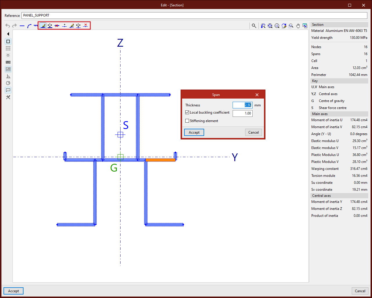
Entering straight segments
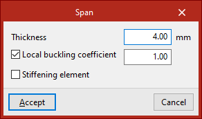
From the "New" button, one or more straight segments can be added. The program allows specifying a "Thickness" in the units defined in the project, activating and entering the "Local buckling coefficient", and indicating whether it is a "Stiffening element".
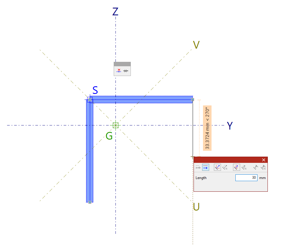
After clicking "Accept", left-click in the viewer to place the segments. Multiple segments can be entered by clicking in several points.
Additionally, the pop-up panel provides options to "Delete last entered point" and "Delete all entered points".
When finished, right-click to end the input.
| Note: |
|---|
| Sections with multiple disconnected parts cannot be defined. |
Entering curved segments
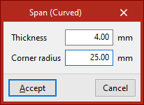
To enter a curved segment, click on the "New (Curved)" option. In this case, the "Thickness" and "Corner radius" must be defined.
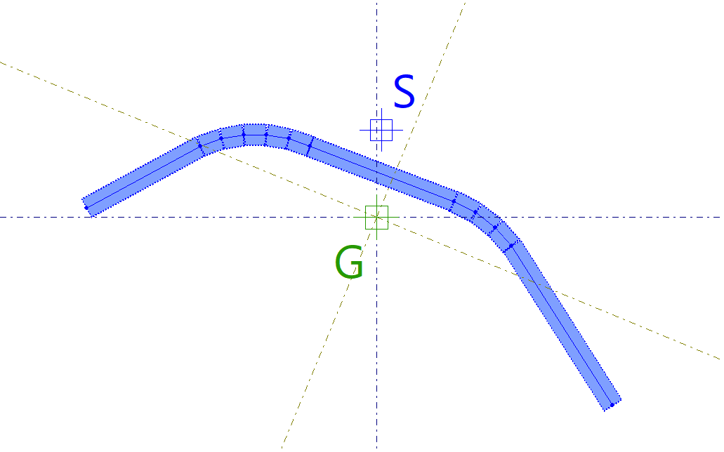
Then, two points are entered in the viewer to define the curved segment.
The program draws a polyline of successive straight segments approximating the curve using the given radius.
| Note: |
|---|
| Curved elements cannot have any free edges. |
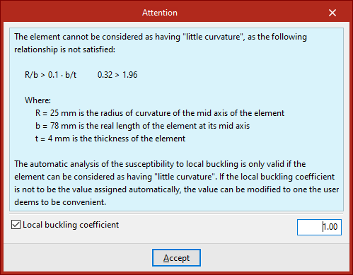
When drawing a curved element, a warning will appear if it cannot be considered "slightly curved", due to not meeting the geometric ratio shown in the warning.
The validity of the automatic local buckling susceptibility analysis depends on whether the element can be considered "slightly curved".
If you do not wish to use the automatically assigned local buckling coefficient, you can modify it as needed by enabling the "Local buckling coefficient" checkbox at the bottom of the warning.
Entering flat elements reinforced with stiffeners
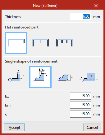
The next option, "New (Stiffener)", allows you to enter a flat element reinforced with stiffeners.
First, the "Thickness" is defined.
Then, specify the "Type of reinforced flat element" and the "Type of simple stiffening" associated:
- If a "Flat external element with end flange or bulb" is defined, the stiffener can be standard, trapezoidal bulb, circular bulb, or generic.
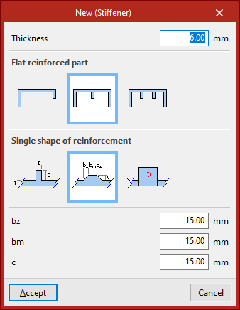
- If a "Flat internal element with a central longitudinal stiffener" or a "Flat internal element with two equally spaced longitudinal stiffeners" is defined, the stiffener can be standard, trapezoidal, or generic.
En la parte inferior se escriben los pIn the lower part, parameters defining the stiffener geometry are entered. For a "Generic stiffener", the "Moment of inertia with respect to axis s" is defined.
After clicking "Accept", left-click two points to place the segment.
A flat element with one or two stiffeners will be generated automatically, depending on the selected options.
Special aluminium section editing tools
The remaining options in the top bar allow you to modify the entered geometry:
- With "Edit", you can click on a segment and modify its properties.
- Using "Move", click the left mouse button on a node or segment to change its position.
- To "Delete" segments, after selecting the relevant option, use the left mouse button to select segments individually or define a selection area, then right-click to delete them.
- You can also enter a "New" node. In this case, indicate whether it is a "Longitudinal weld" or not, then click a point on a segment to add it.
- If you want to modify a node’s characteristics, after selecting "Edit", left-click the node to select it.
- With the next option, you can "Move" nodes by left-clicking and defining their final position.
- Using "Delete", nodes can be selected individually or by area, then deleted with a right-click. In this case, associated segments will also be removed.
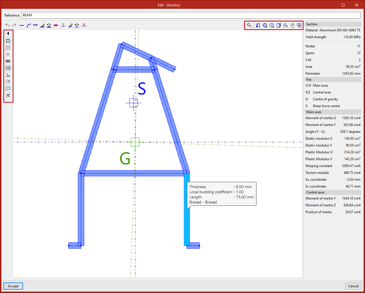
Auxiliary tools in the viewer
During the segment input process, you can use "Snaps", activated in the left panel, along with other tools in the viewer's left column.
With "Show information texts" activated, moving the pointer over segments and defining nodes displays information about them.
Using the mouse wheel in the viewer allows zooming. Pressing and dragging the wheel or middle mouse button pans the image.
The tools in the top right corner of the viewer also allow these actions and are common across other program viewers.
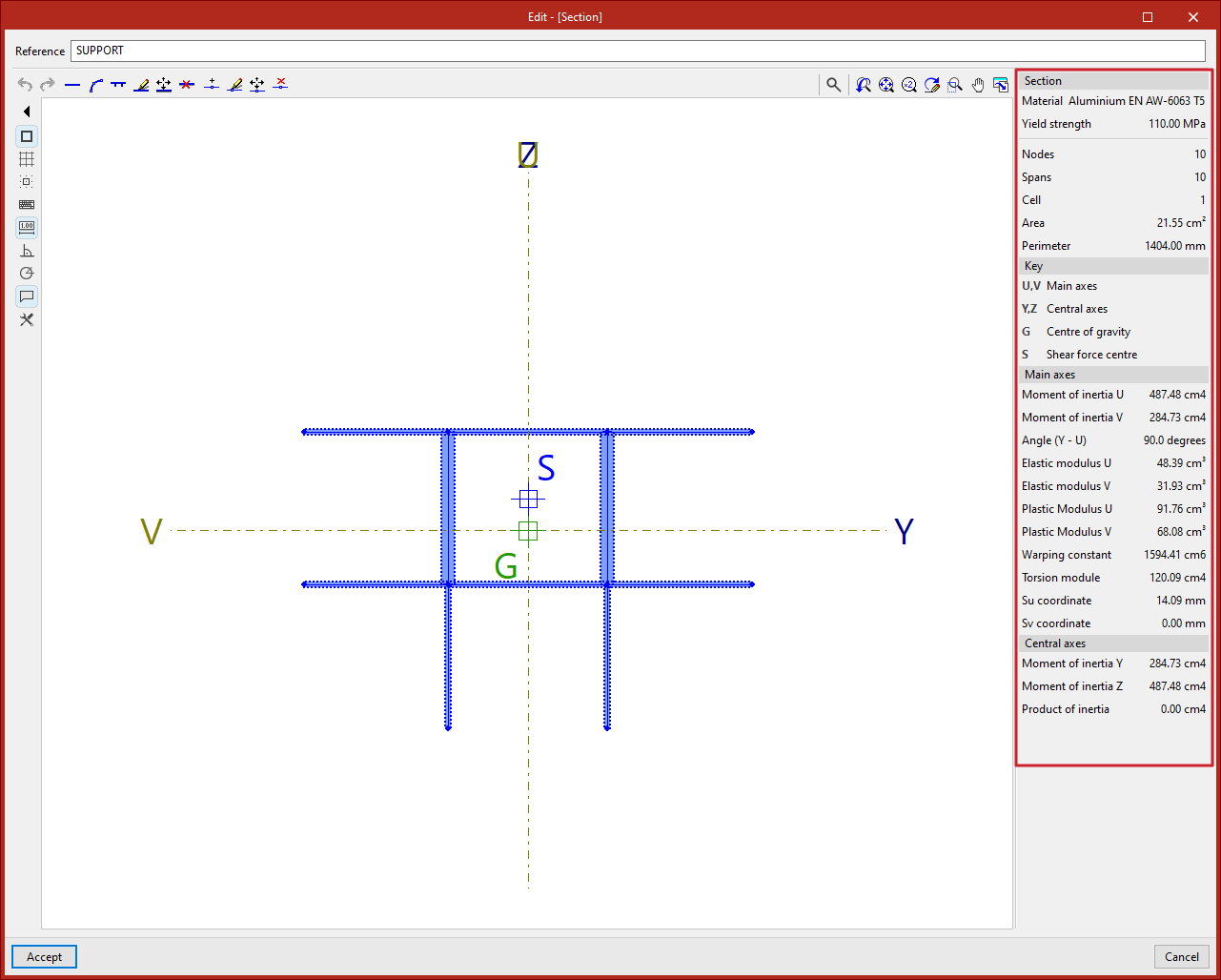
Special aluminium section data
On the right panel, the program automatically displays analysed data for the entered "Section", such as the number of "Nodes", "Segments", and "Cells", along with "Area" and "Perimeter".
Below this, you’ll find the "Legend". The program shows the principal axes U and V and the central axes Y and Z of the section.
It also shows the "Centre of gravity" G and the "Shear centre" S.
At the bottom, various calculated values related to the principal and central axes of the section are listed, including moments of inertia, elastic moduli, and plastic moduli.
Finally, by clicking "Accept", you exit the section editor and return to the "Describe" window.
Clicking "Accept" again applies the defined section to the selected group of bars.