Entering ties
The program allows you to enter ties, that is, pin-ended straight-axis bars that only resist axial tensile forces along their axis, using the following options.
Ties inserted in this way are designed using a specific method outlined below and can only be defined within braced panels.

Accessing the definition of ties
Ties are defined either when inserting a new bar (using the "New" option) or by editing an existing bar via the "Section" option.
Both options are available in the "Bars" group on the top toolbar, under the "Geometry" tab (within the "Structure" tab).
In the "Describe" window, in the upper "Type of structural element" section, select "Tie".
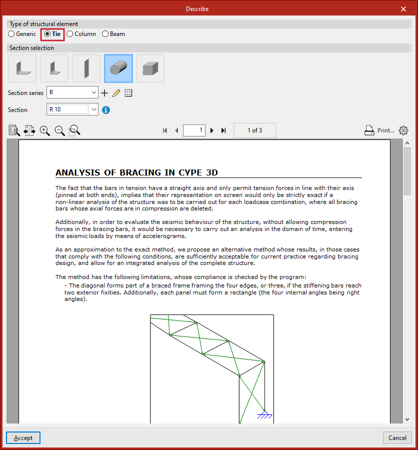
Selecting the tie section
Next, carry out the "Section selection" from the categories offered by the program:
- Symmetrical angle
- Angle
- Plate
- Round bar
- Square bar
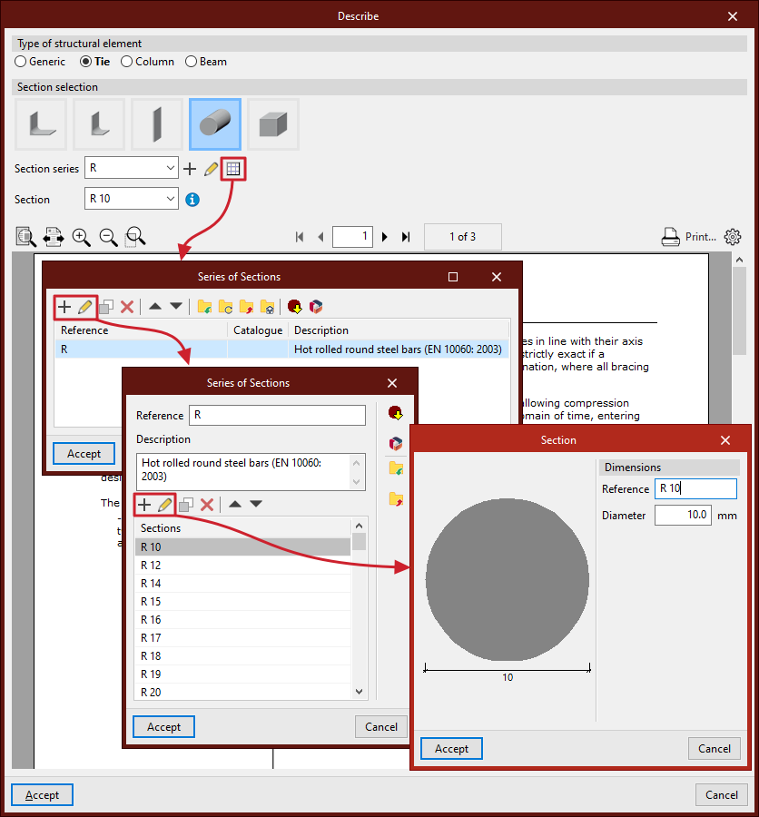
Subsequently, the drop-down menus allow you to select the "Series of sections" and the "Section" within that series.
As with "Generic" sections, you can create and edit a series of sections using the buttons located to the right.
Analysing ties
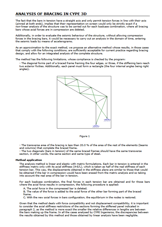
At the bottom of the "Describe" window, a help text related to "Analysis of bracing in CYPE 3D" is displayed. It explains the methodology used by the program to analyse these elements and outlines their limitations.
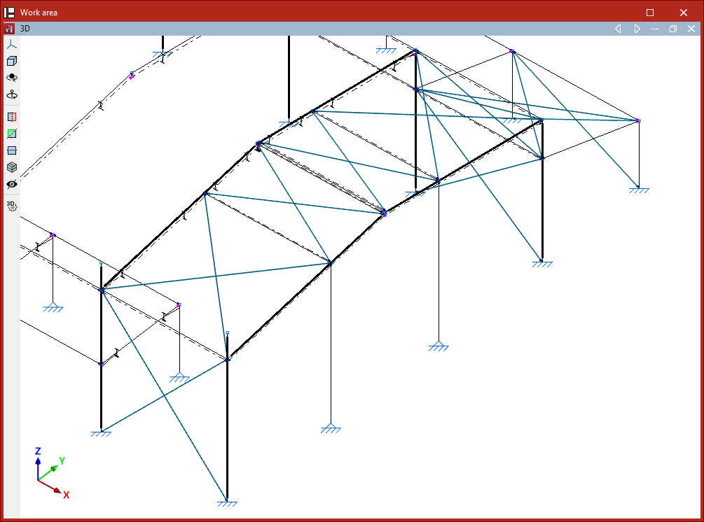
Placing ties in the model
After configuring the tie section in the "Describe" window, click "Accept" to insert it into the workspace.
The tie is defined by its start and end nodes. To insert it into the model, select two points with the left mouse button. To confirm the insertion of the tie, click the right mouse button.
Ties must form part of a braced panel arranged in the shape of a Saint Andrew’s cross.
This panel must be framed at its edges by four bars located in the same plane and forming a rectangle, meaning all four internal angles must be right angles.
It is also possible to define the perimeter of a braced panel using only three bars if the end of two of them is stiffened by an "External fixity", such as in a portal frame formed by two vertical bars connected by a horizontal beam.
The two diagonals of a braced panel must be made of the same material and have the same cross-section. Additionally, the cross-sectional area of the ties must be less than 20% of the area of the other elements forming the perimeter of the panel.
Finally, it is advisable to ensure that when inserting ties within the same panel, the "Generate nodes at intersection points" option from the "Bars" group in the "Geometry" tab remains deactivated, as the elements must remain independent of each other.