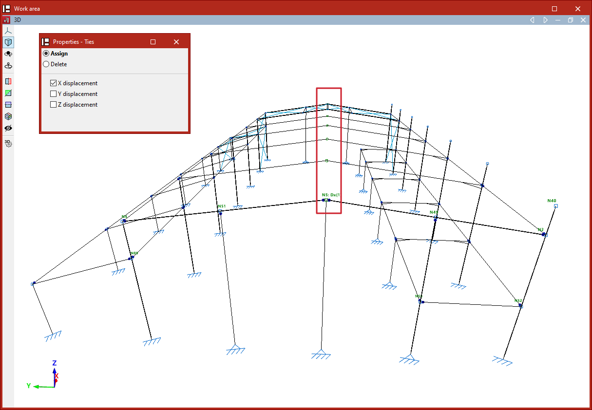
Defining node ties
The assignment and removal of node ties is carried out using the following option, available in the "Bars" group on the top toolbar, under the "Properties" tab (in the "Structure" tab).

Node ties are used to enforce that two or more nodes have identical displacements in all load cases.
To apply this condition, the actual structure must include some element or construction detail that effectively guarantees the equality of displacements, even if it is not graphically represented in the model.
Assigning ties
After clicking on "Ties", in the "Properties – Ties" window, if "Assign" is selected, you can choose whether to equalise "X displacement", "Y displacement", or "Z displacement". These directions refer to the global axes.
Displacements can be equalised in one, two, or all three directions simultaneously by checking the corresponding boxes.
After selecting the desired options, proceed to select the nodes to be tied by clicking on them one by one with the left mouse button or by defining a selection area.
Then, right-click to confirm the selection.
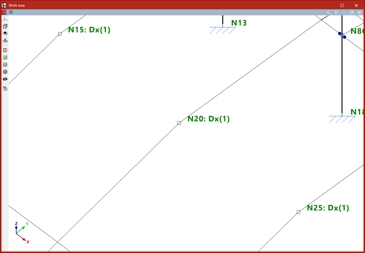
Once this is done, a text will appear next to the node reference indicating the existence of a tie in each spatial direction, along with an ID number used to differentiate the various groups of nodes with tied displacements.
This information can also be viewed by hovering the pointer over the corresponding node.
Deleting ties
You can "Assign" new ties and "Delete" existing ones from the "Properties – Ties" window.
First, select the directions in which you want to remove the ties.
Then, select the nodes one by one using the left mouse button or by defining a selection area.
Upon right-clicking, the node will lose the ties previously defined in the selected directions.