
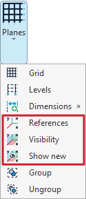
Visibility of planes and reference lines
The display of planes and reference lines is managed using the tools available in the "Planes" menu of the group with the same name in the top toolbar, within the "Geometry" tab (under the "Structure" section).

Reference lines are graphical supporting elements perpendicular to the global axes, which make the insertion of new structural elements easier by enabling snapping.
The options related to the visibility of reference lines are:
- References
- Visibility
- Show new
Each of these tools is explained below:
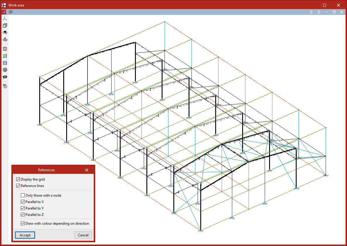
References
The "References" option opens a dialogue box where you can tell the program whether to "Display the grid" (inserted using the "Grid" option in the same menu) and manage the visibility of "Reference lines" by checking or unchecking the corresponding boxes.
Within the reference lines section, you can choose to display "Only those with a node", or only lines that are "Parallel to X", "Parallel to Y", or "Parallel to Z".
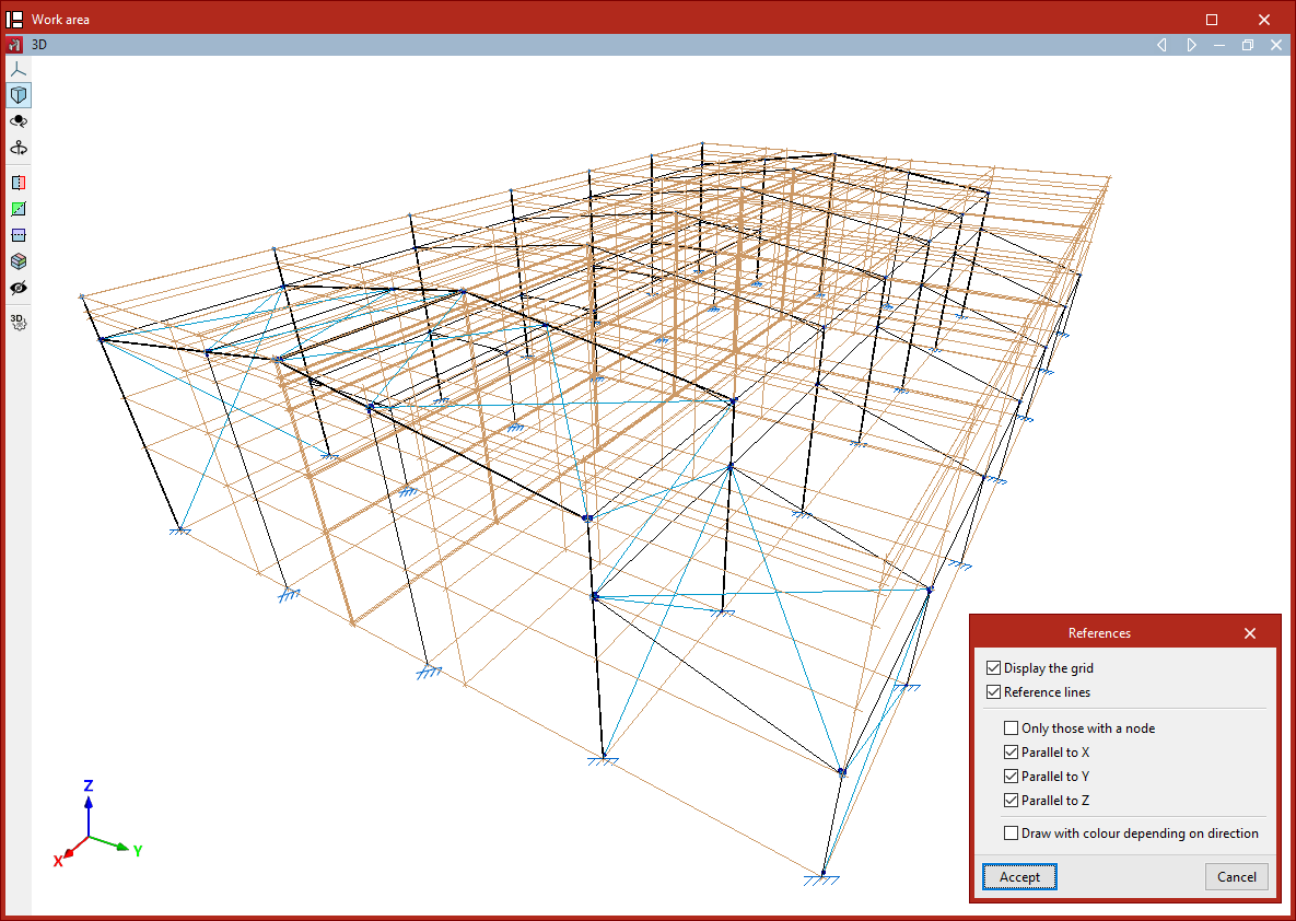
If the "Draw with colour depending on direction" checkbox is enabled, the program will display the reference lines using a different colour for each of the three spatial directions.
Click "Accept" to apply the changes to the model.
Visibility
The "Visibility" option allows you to select a group of nodes and either show or hide the reference lines of the planes that contain them.
To do this, in the "Show/Hide planes" dialogue box that appears after clicking the option, first choose whether to "Show" or "Hide" the lines by selecting the corresponding option, then click "Accept".
Next, select the group of nodes where the setting should be applied by left-clicking on them one by one, or by marking a selection area.
Finally, confirm the operation by right-clicking.
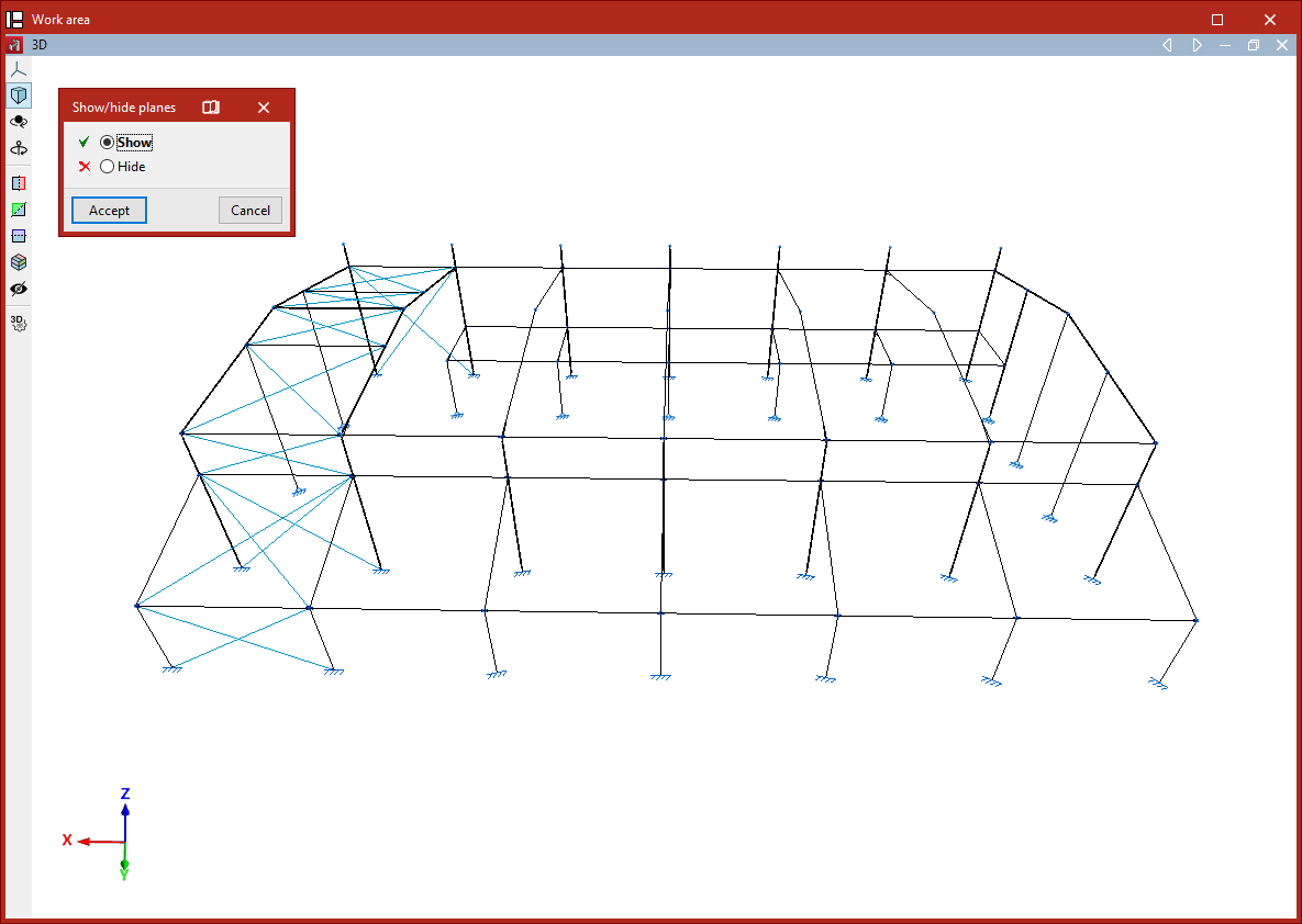
Process to hide or show reference lines in planes
Show new
The "Show new" option manages the visibility of reference lines in planes generated when new nodes are inserted into the structure.
If this option is active (it will appear highlighted in the "Planes" menu), then when nodes are inserted—whether by using the dedicated insert nodes option or by inserting the ends or vertices of bars or shells—the reference lines associated with them will be visible.