
Sketch design tools

CYPE Architecture’s sketching tools ensure the program is highly flexible and versatile. Modelling started in the "Sketch" tab can later be transformed into "Building elements" in the "Architecture" tab.
For sketch-type elements, the geometry consists of the following:
- Lines that can be created with different tools (arcs, circles, polygons, etc.).
- Surfaces consisting of two faces, which can be coloured independently, and also created using different tools (arcs, circles, lines, polygons, etc.). The surface areas are automatically generated each time a set of lines forming a closed polygon is drawn.
As well as a general layer, which contains all the information created with the sketch tools, both lines and surface areas can be associated with separate visibility layers. See more on this topic in the "Managing the visibility of the project elements" section.
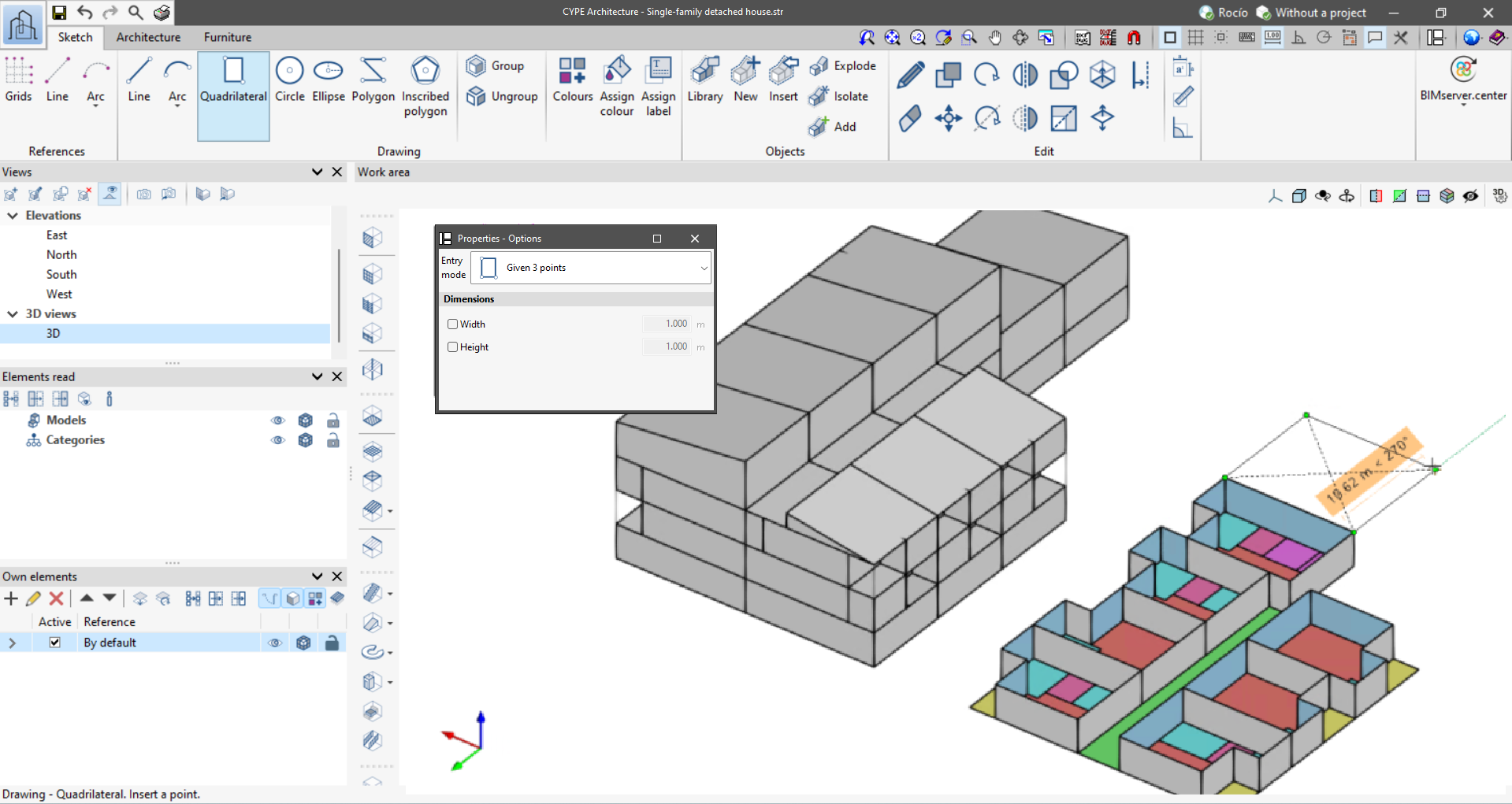
The main tools for designing sketch elements are as follows:
 | Line | Enter general lines. |
 | Arc | Enter arcs. The accuracy can be determined using the "Number of segments" field. |
 | Quadrilateral | Enter quadrilaterals. They can be entered using 3 points, diagonally or by selecting a point. |
 | Circle | Enter circles. The accuracy can be determined using the "Number of segments" field. |
 | Ellipse | Enter ellipses. The accuracy can be determined using the "Number of segments" field. |
 | Inscribed polygon | Enter inscribed polygons. The accuracy can be determined using the "Number of segments" field. |
Furthermore, all elements drawn with the aforementioned tools can also be edited using the "Edit sketch elements" tools.
