Inserting bolts
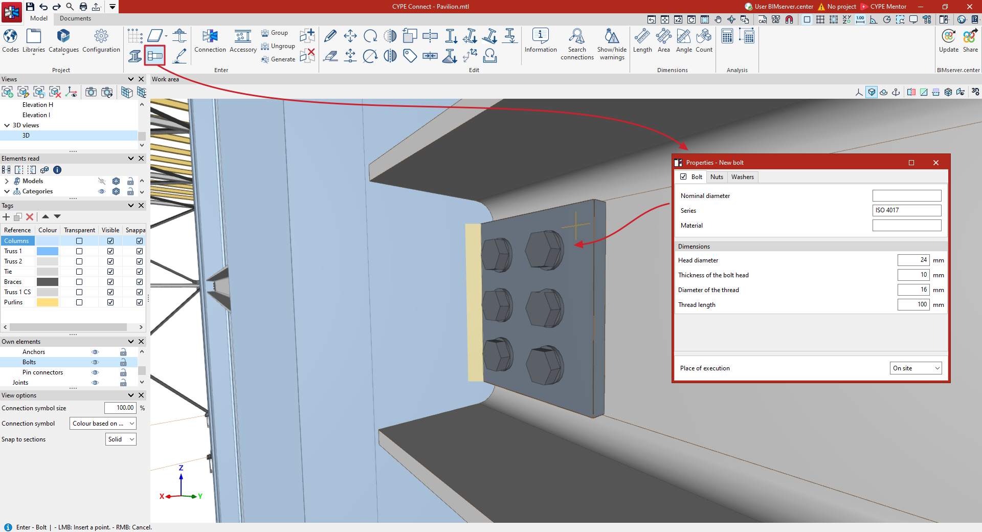
To insert bolts into the general model of the structure, in the "Model" tab of the program interface, select the "Bolt" option from the "Enter" group on the top toolbar.

Bolt
After clicking on the "Bolt" option, a window appears where you can define the properties of the new bolt.
| Note: |
|---|
| This tool allows bolts to be freely inserted to complete the structure’s detail drawing at specific points. However, if the aim is to model connections, including their calculation and code compliance checks, it is advisable to use the "Connection" option instead, where bolts can also be inserted using the specific operation. |
Defining bolt properties
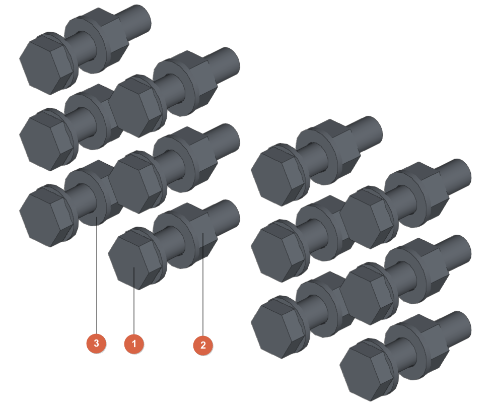
The various tabs available show details of the "Bolt" itself (1), the "Nuts" (2) and the "Washers" (3), where applicable.
Further down, in the drop-down menu at the bottom, you can select whether the "Installation location" is "On site" or "In the workshop".
"Bolt" tab
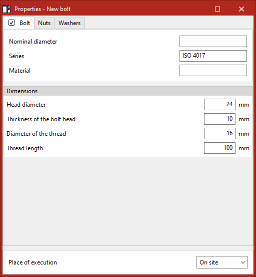
To define the bolt itself, select this tab and enter the "Nominal diameter", the "Series" and the "Material", as well as the "Dimensions" for the following parameters:
- Head diameter
- Thickness of the bolt head
- Diameter of the thread
- Thread length
"Nut" tab
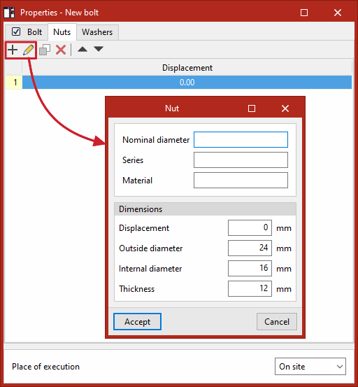
To define the nuts and/or locknuts, entries must be added to a table in which they are listed with their "Displacement" value, which indicates the distance between each nut and the base of the bolt head.
For each nut, the reference number for its "Nominal diameter", "Series" and "Material" is entered, along with the "Dimensions" for the following parameters:
- Displacement
- Outer diameter
- Inner diameter
- Thickness
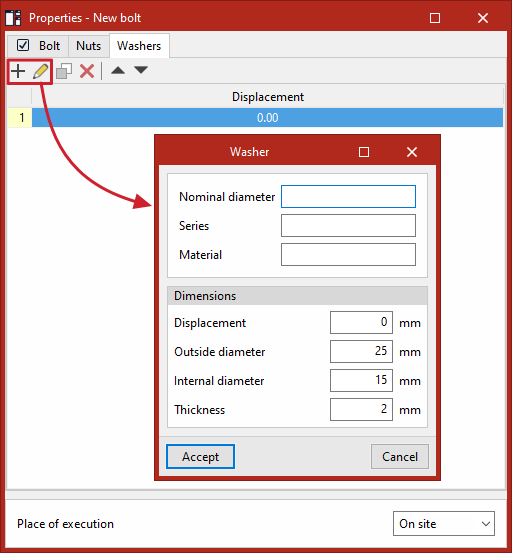
"Washers" tab
To define the washers, entries must be added to a table in which they are listed along with their "Displacement" value, which indicates the distance between each washer and the base of the bolt head.
For each washer, the reference for its "Nominal diameter", "Series" and "Material" is entered, as well as the "Dimensions" for the following parameters:
- Displacement
- Outside diameter
- Internal diameter
- Thickness
Placing bolts in the work area
To insert the bolt into the model, use the left mouse button to select a group of elements one by one or to highlight a selection area. Then, click the right mouse button to confirm the selection.
The program now allows you to position the bolt by placing the cursor on any of the faces of the selected elements. Clicking the left mouse button inserts the bolt.
From here, you can insert new bolts with the same properties by left-clicking again at other points on the selected elements in the model.
The "Properties" window remains open in case you wish to make any changes to these settings. These changes will apply to any new bolts added after they have been modified.
Finally, you can right-click to deselect the group of elements, and if you right-click again, the operation is completed.