
Introduction
CYPE Connect is a tool with two main functions:
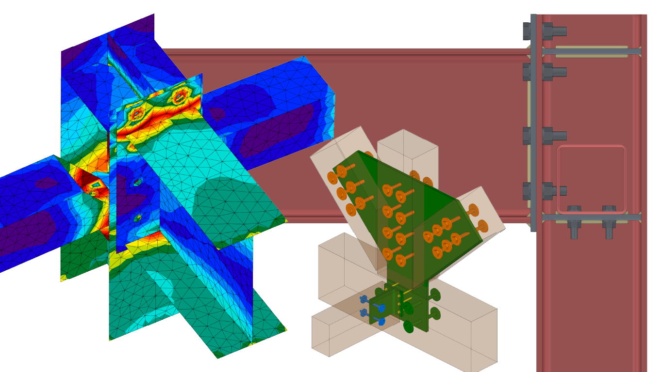
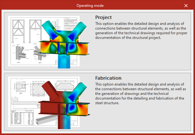
- In "Project" mode, it enables the modelling, calculation and regulatory verification of connections in steel and timber structures using the finite element method. The program incorporates the OpenSees© analysis engine, developed at the University of California, Berkeley, to perform comprehensive analyses. In addition to calculations and checks, CYPE Connect features a tool for generating sheets with assembly drawings of the connections.
- In "Fabrication" mode, in addition to the above, the program enables the creation of detailed cut-out drawings for steel and timber structures for workshop fabrication. To do this, the app allows users to compile detail drawings of structural components and assemblies, and provides fabrication files in DSTV, STEP, IFC EM.11 or DXF formats for plates.
The program includes various tools for modelling or importing a BIM model and can be used to accurately define all the elements required for analysing connections and/or creating the fabrication drawings for the structure, such as structural sections, sheet metal, bolts, weld beads and anchors.
Home
When you launch the program and create a new project, the program allows you to select different work modes, as well as import data from structural models created in programs such as CYPECAD or CYPE 3D to simplify the data entry process.
The link below provides detailed information on the options available during the initial process of creating new works, guidance on possible workflows and the general sequence of data input and output, as well as options for importing data from other programs.
Work environment
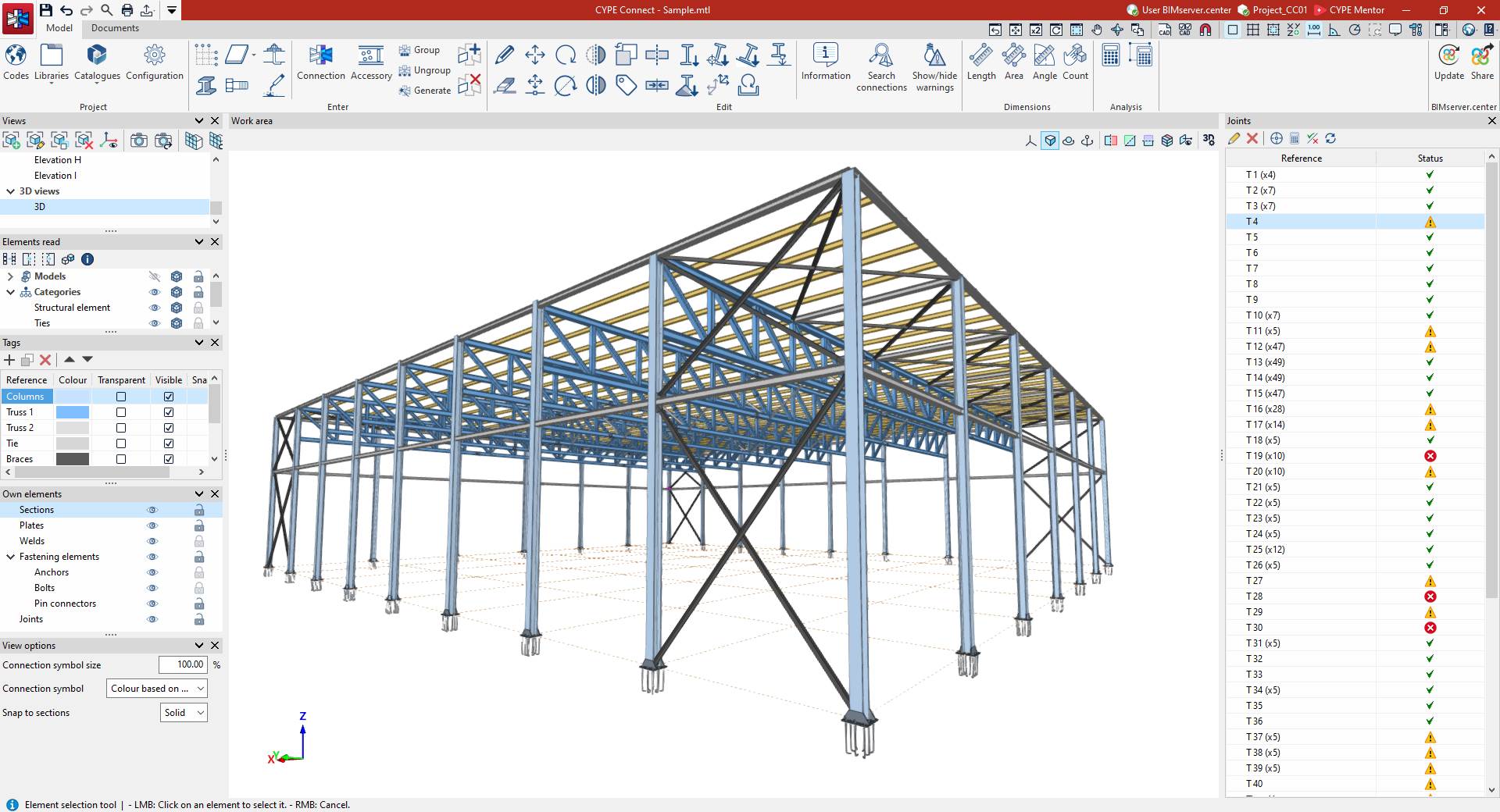
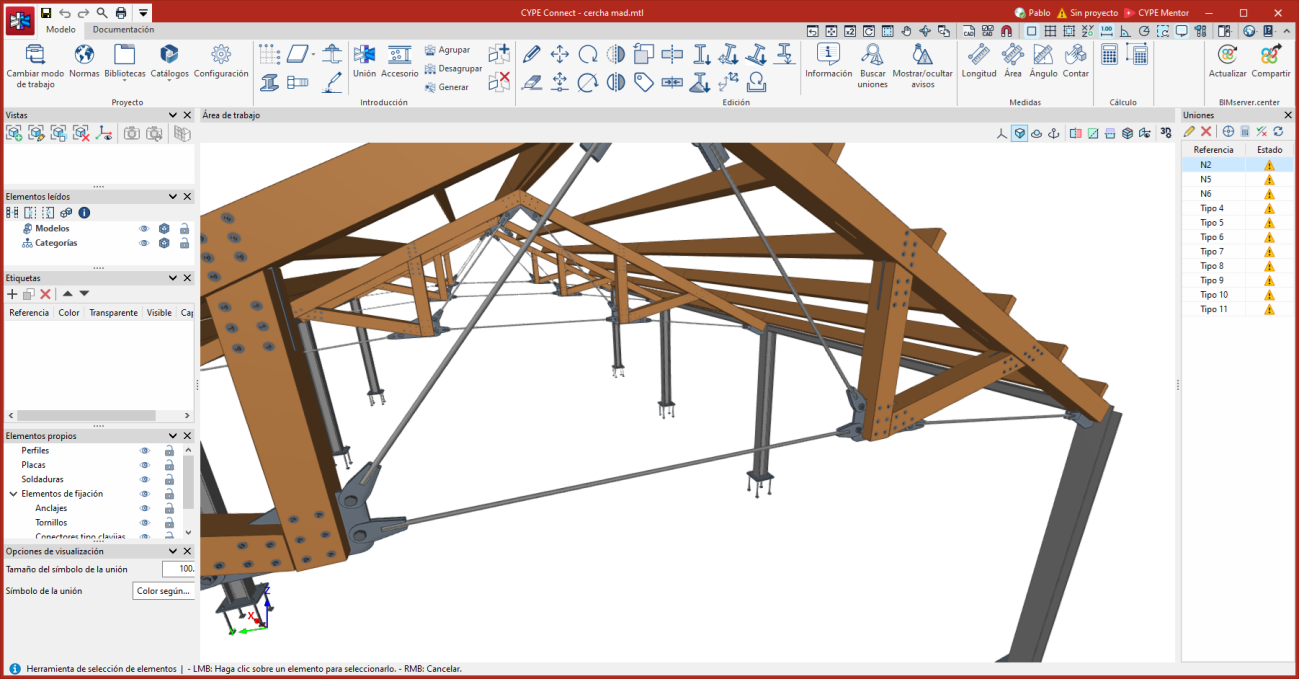
The CYPE Connect user interface is similar to that of other CYPE modelling tools and features a system of dockable windows that can be customised to adapt the workspace to the project’s requirements.
In the top left-hand corner of the screen, there are two separate tabs: "Model" and "Documents":
"Model" tab
The "Model" tab in the program’s main interface allows you to adjust the general project settings (including the selection of standards and libraries of structural elements and materials), add or modify structural elements in the workspace, generate and/or group connections and fittings, and access the connection editor, from where they can be designed and analysed.
The following link provides a detailed overview of the options offered by the program under the "Model" tab:
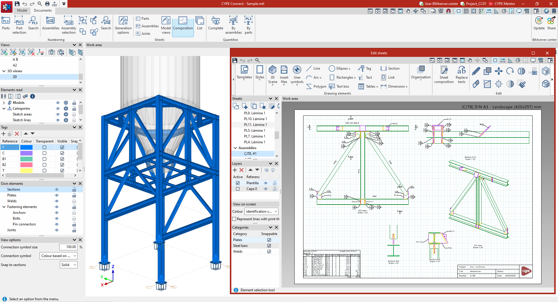
"Documents" tab
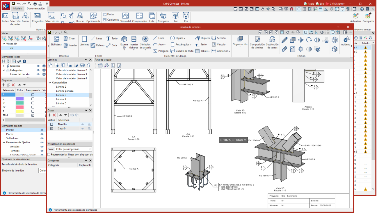
The "Documents" tab in the program’s main interface allows you to number parts and assemblies (in "Manufacturing" mode) and to create drawing sheets for parts, assemblies, connections and/or model views, amongst other things. This way, the graphical documentation of the elements making up the structure is managed in detail.
You can view detailed information about the options offered by the program under the "Documents" tab via the following link:
Connection editor
The connection editor features an interface with three tabs at the top: "Model", "Analysis" and "Sheets":
Model
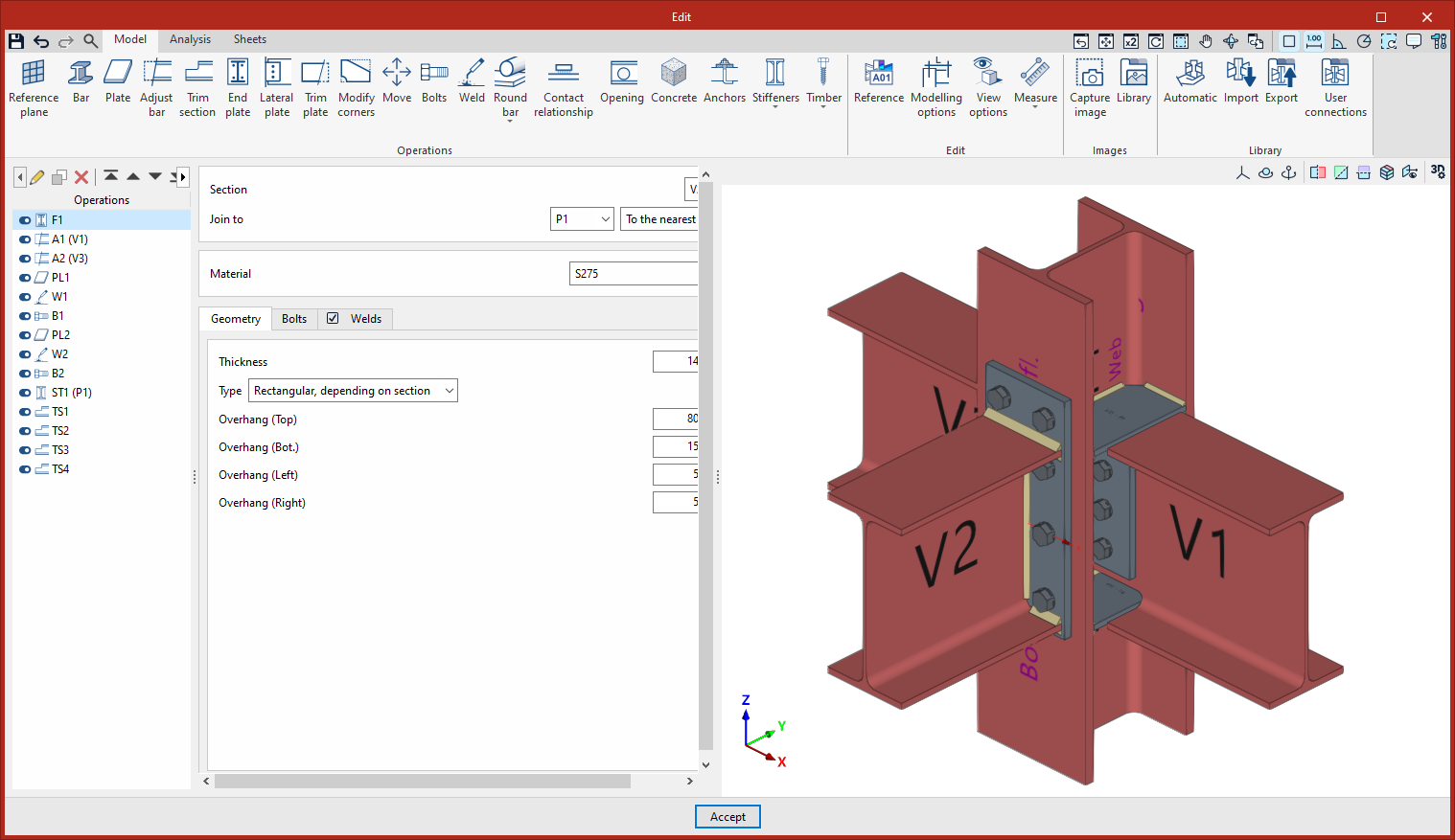
On the first tab, "Model", you can carry out the complete modelling of the connection, adding and modifying its various components.
Connection elements can be entered or adjusted through a series of operations, as well as by importing connection types from the connection libraries or using parametric connections.
Calculation
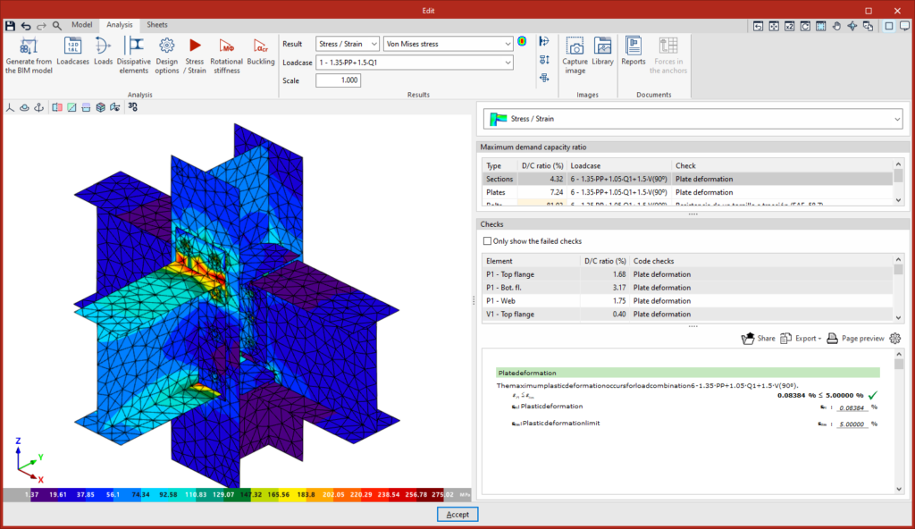
Once the model has been completed, you can access the "Analysis" tab, where the analysis and verification of the connection are carried out.
The available analyses include the stress-strain analysis, rotational stiffness analysis and buckling analysis. The program displays the analysis results in the built-in viewer and provides detailed lists of checks against standards.
This tab is not available when editing fittings.
Prints
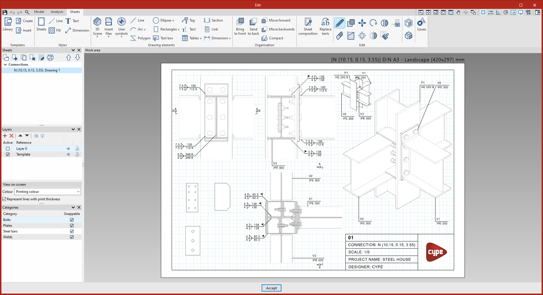
Once you have modelled and analysed a connection, you can move on to the "Sheets" tab, where you will find the tools for creating detail drawings.
Alternatively, you can access this interface for working with connection sheets from the "Documents" tab in the main interface by selecting the "Connections" option from the "Sheets" section.
Here, you can create views of the connection model at the desired scale, which are dynamically linked to the model. The program also features traditional drawing tools and design tools.
Results output
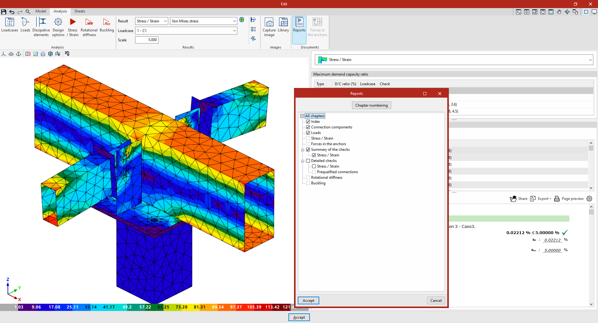
Project reports
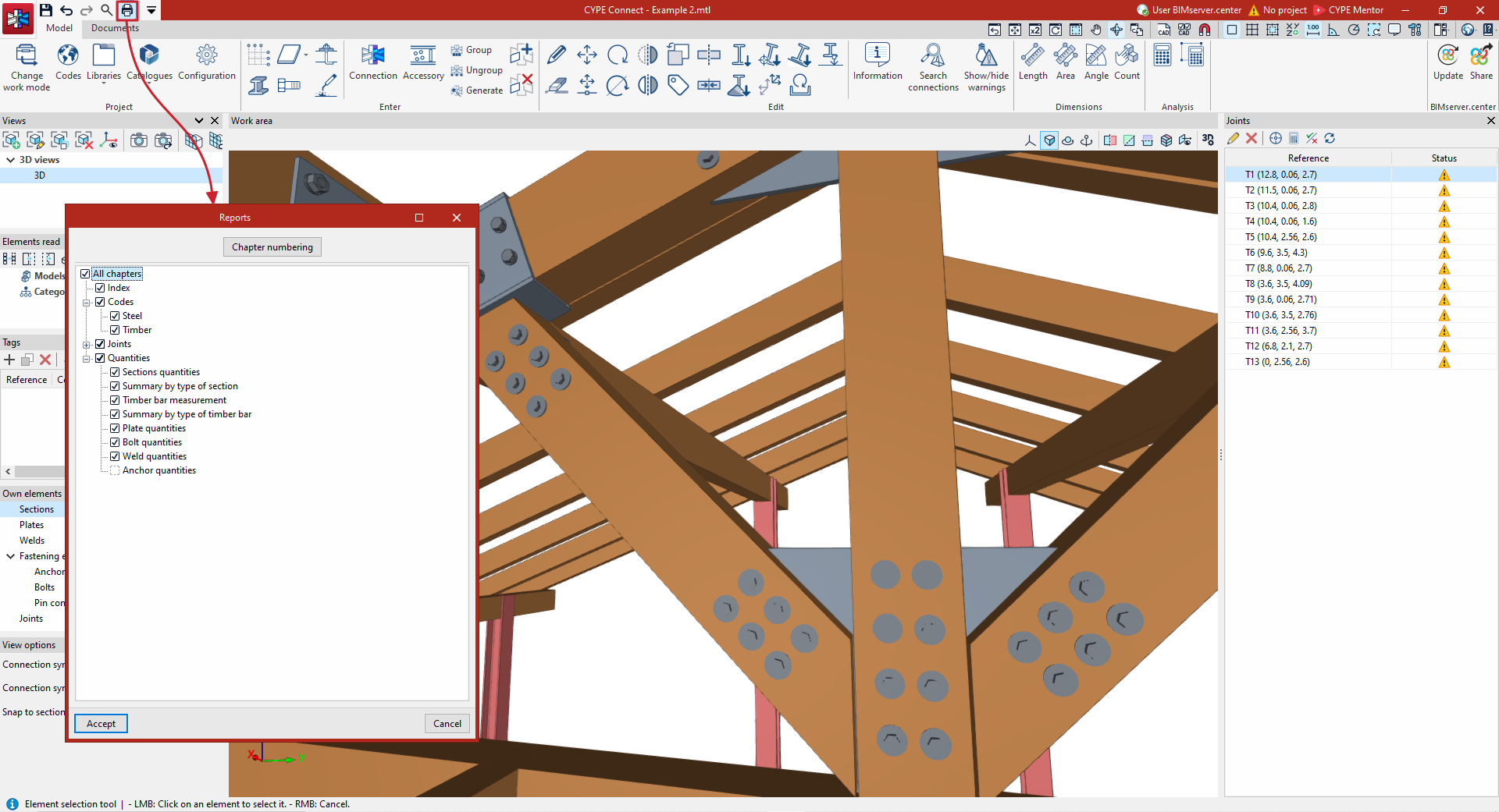
You can print reports generated by the model directly from within the program, or generate HTML, PDF, TXT, RTF or DOCX files.
This includes the following chapters:
- Index
- Codes
- Joints
- Components of the joint
- Loads
- Stress / Strain
- Forces on the anchors
- Summary of code checks
- Detailed checks
- Rotational stiffness
- Buckling
- Quantities
- Assembly quantities
- Assembly and part quantities
- Sections quantities
- Summary by type of section
- Timber bar measurement
- Summary by type of timber bar
- Plate quantities
- Bolt quantities
- Weld quantities
- Anchor quantities
Quantities reports
Under the "Documents" tab, in the "Quantities" section of the main toolbar, you will find the features required to generate quantities reports for the structural elements.
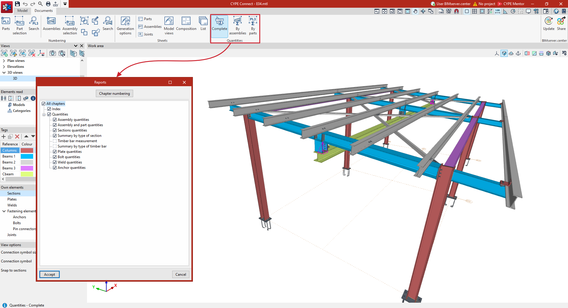
Connection analysis results
On the "Analysis" tab within the connection editor, you can:
- View the results of the analyses carried out on screen, including a 3D view and a review of the checks carried out on each element.
- Print the specific result reports for the connection currently being edited, or export them to various formats.
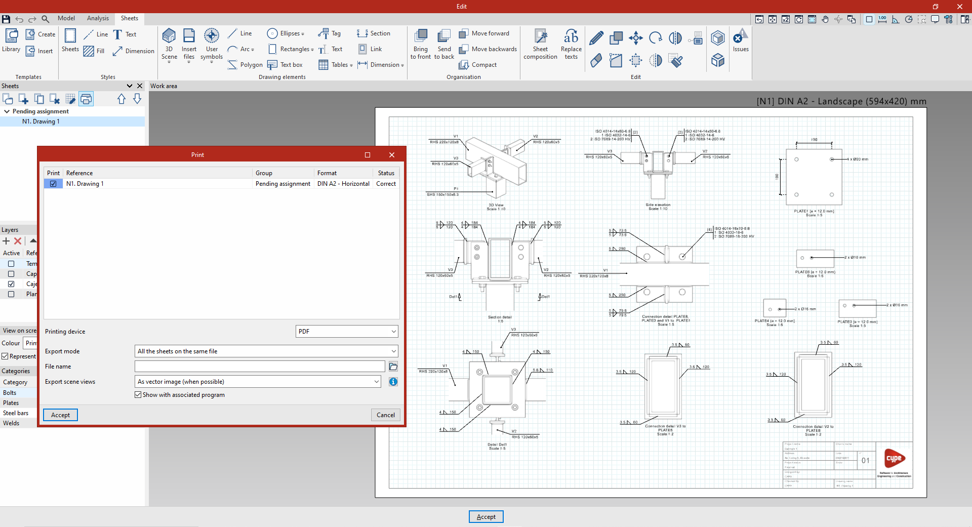
Drawings in DWG, DXF or PDF format
The drawings generated in the program using the options available in the sheet editor can be exported in DWG, DXF or PDF format.
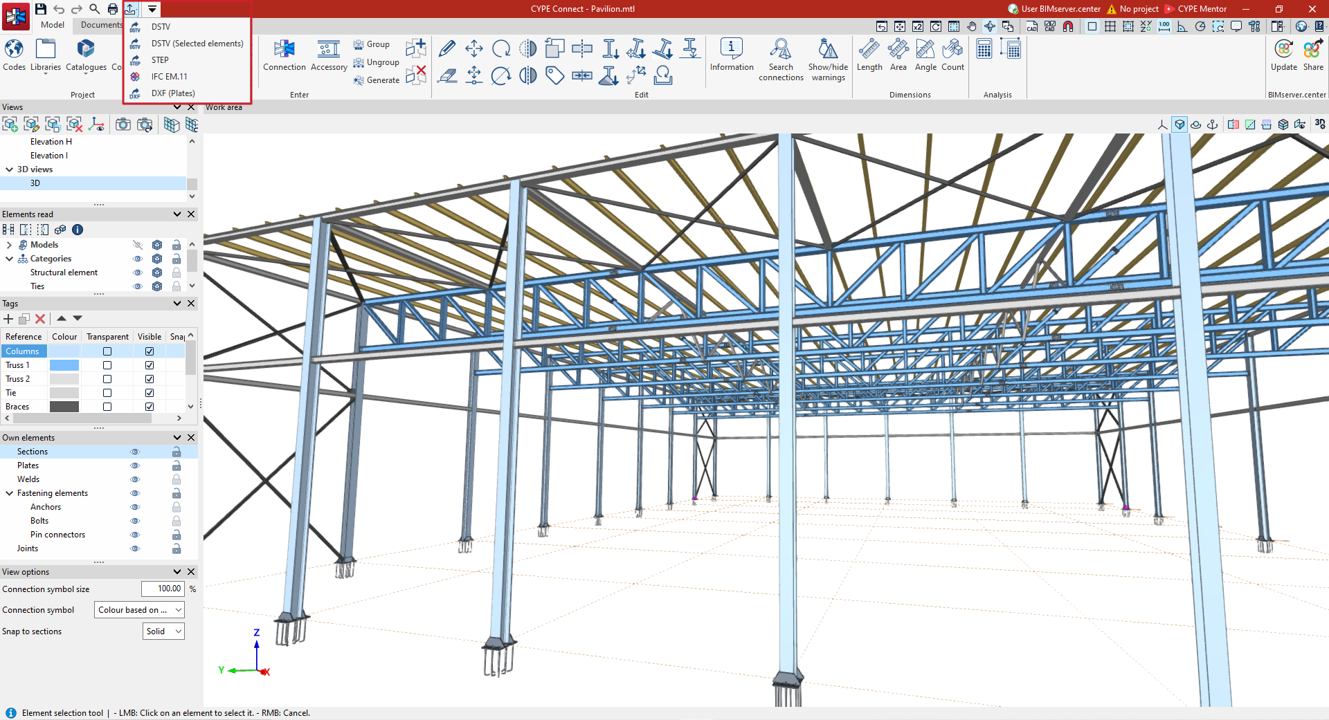
Manufacturing files (DSTV, STEP, DXF)
Models in DSTV and STEP formats can be exported in two ways: via the export settings for the BIMserver.center platform, which appear when you click the "Share" option, and via the options in the "Export" menu, located in the top-left corner of the program’s home window.
- The DSTV format is an industry standard defined by the German Steel Construction Association (Deutscher Stahlbau-Verband). From the "Export" menu options, you can generate a .dstv file for the entire model (the "DSTV" option) or for selected elements only (the "DSTV (Selected elements)" option).
- The STEP format (ISO 10303) enables the exchange of data between design and manufacturing systems (CAD, CAM, CAE). When exporting to STEP format, the program allows you to choose whether or not to include each category of element ("Sections", "Plates", "Bolts", "Welds", "Anchors", "Pins", "Bolts" and/or "Screws").
- In addition, the "Export" menu offers an option to export the plates to a .dxf file for manufacturing.
Exporting the exploded view model in IFC EM.11 (Exchange Model 11)
EM.11 is an MVD (Model View Definition) specification of the IFC format that contains information for the automated fabrication of steel. The program exports data using this format for sections, plates, welds, bolts and ties.
The IFC EM.11-format detailing model can be exported in two ways: via the export settings for the BIMserver.center platform, which appear when you click the "Share" option, and via the "Export" menu option, available in the top-left corner of the program’s start window.

| Note: |
|---|
| The "Export" menu in the program’s main interface is only available in the "Fabrication" work mode. |
GLTF file compatible with BIMserver.center
When you export the project to the BIMserver.center platform, a 3D model in GLTF format is automatically exported for integration into the Open BIM project, enabling the model to be visualised:
- On the online platform
- In the BIMserver.center app for iOS and Android
- In virtual reality and augmented reality
- In other CYPE programs
Integrating StruBIM Steel features into CYPE Connect
As of version 2027.a, all the features of StruBIM Steel (discontinued program) have been integrated into CYPE Connect, resulting in a single, more comprehensive, efficient and coherent solution. This integration brings all the features together in a unified and more intuitive environment, offering an optimised user experience and a more streamlined and simplified workflow.
With this integration, CYPE Connect incorporates all the features previously available in StruBIM Steel, maintaining its original power and expanding it with new possibilities.
Starting with this version, StruBIM Steel will no longer be released as a standalone product; all its features will be integrated into CYPE Connect. To ensure continued work and a smooth transition for users, as of version 2027.a, CYPE Connect allows you to open and continue projects created previously in both CYPE Connect and StruBIM Steel.
The CYPE Connect environment can be used to model, edit and modify steel and timber structures all in one place, as well as to define, analyse and verify the connections between the various structural elements. Furthermore, the app can generate all the project’s graphical documentation from a single source, including both drawings showing connection details and drawings depicting the structure as a whole.
For reference, please consult the following information to learn about the features of CYPE Connect version 2026.c and earlier, as well as the features of StruBIM Steel, both of which have been integrated into CYPE Connect as of version 2027.a:
Table of contents
Complete your tour of CYPE Connect by exploring the other sections available: