

Workflows supported by the program
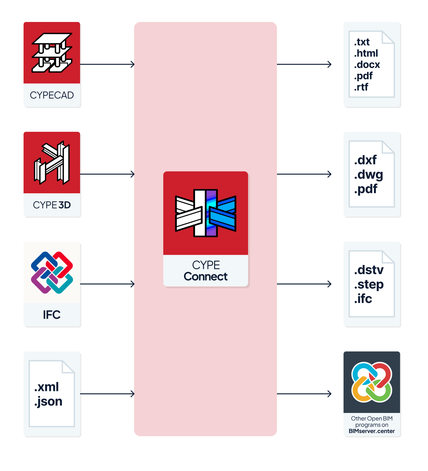
As CYPE Connect is an Open BIM tool and is connected to the BIMserver.center platform, it offers a range of workflow options.
Data entry
Free-form modelling
- Design the structure by entering the data freely in CYPE Connect.
Importing BIM models
If a CYPE Connect project is linked to a BIM project on the BIMserver.center platform, the following can be carried out:
- Importing structural models hosted on BIMserver.center. This enables the generation of structural elements, the import of element types and associated materials from the library, the import of connections (generating connections at their locations) and the forces in the bars, thereby allowing the connections to be calculated subsequently. The available options include the following:
- Importing a structure previously analysed in CYPECAD.
- Importing a structure previously analysed in CYPE 3D.
- Importing structural models in IFC format uploaded to the BIMserver.center project via the web platform.
Importing XML and JSON files
If you have XML or JSON files containing structural information generated by other programs, you can carry out the following:
- Importing structural models and their forces from an XML file generated by ETABS®.
- Importing structural models and their forces from an XML file generated by SAP2000®.
- Importing structural models and their forces from JSON files generated by any program.
Data output
- Exporting reports to HTML, DOCX, PDF, RTF and TXT formats.
- Exporting drawings to DXF, DWG and PDF formats.
- Exporting manufacturing files in DSTV, STEP, IFC EM.11 and DXF formats for plates.
- Exporting the data generated using CYPE Connect to the BIMserver.center platform in IFC and glTF formats. This allows the data to be viewed by authorised project participants.
Work modes
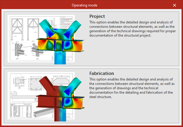
CYPE Connect has two work modes: "Project" and "Fabrication", designed to meet users’ needs at different stages of the structure’s development. Both modes share similar tools and options for structural modelling and connection definition, providing a common working environment.
The main difference between the two modes lies in how documentation is managed and generated. Each work mode organises its tools and graphical outputs according to the intended final deliverable, thereby supporting a more focused workflow tailored to each process.
Project mode
The "Project" mode is intended for the technical documentation required for the structural design project. In this mode, users can generate and manage general drawings of the structure, as well as include connection views and details, producing documentation focused on the overall design, analysis and definition of the project.
Fabrication mode
The "Fabrication" mode is intended for generating technical documentation used in workshop fabrication and on-site assembly processes. In this mode, users can generate and manage part drawings, assembly drawings, connection drawings and general arrangement views of the structure, producing detailed documentation tailored to production and assembly requirements.
For projects created in "Project" mode, the user has the option to "Change the work mode" to "Fabrication". This option is available in the "Model" tab, within the "Project" section.
| Note: |
|---|
| The "SPD – Steel Structure Detailing Drawings" licence is required to generate drawings in "Fabrication" mode, whereas it is not required in "Project" mode. Export tools for plates in DSTV, STEP and DXF formats, or IFC EM.11, are available in "Fabrication" mode. |
Basic sequence for data input and output when defining structures and designing and analysing connections in CYPE Connect
The definition of structures and the design and analysis of connections within the program can be carried out using the following basic sequence of data input and output:
- Creating a new project (from "File", "New") and select the working mode ("Project" or "Manufacturing").
- (Optional) Linking to BIMserver.center; import structural elements from the BIM model, as well as connections and the associated element and material libraries, and the results for the bars required for designing connections.
- Reviewing the project settings (from the "Model" tab, "Project" section), including the definition of standards, element and material libraries, manufacturers’ catalogues and other settings.
- If the structure has not been imported from the BIM model, the structural elements can be entered directly into the program:
- Entering sections (via "Section" in the "Enter" section on the "Model" tab).
- (Optional) If you do not wish to enter these as operations during the connection definition process, you can enter plates, bolts, anchors and welds via the program's general interface (using the options in the "Enter" group in the "Model" tab).
- (Optional) Defining and analysing connections.
- Generating connections. To do this, you can:
- Enter the connections manually (using the "Connection" option in the "Enter" group).
- Automatically generate connections (using the "Generate" option in the "Enter" group). This option also allows connections to be defined automatically during the generation process.
- If the nodes have been imported from the BIM model, the connections will have been generated automatically during the process of creating the new project or updating the data.
- Defining connections (using the options on the "Model" tab in the connection editor). To do this, you can:
- Define the connection by entering the operations (options in the "Operations" group).
- Import the connection from the user connection libraries or from the predefined connection (options in the "Library" group).
- Analysing connections. There are several alternative ways of doing this:
- Analyse each connection individually (using the options on the "Analysis" tab in the connection editor).
- Analyse multiple connections (using the options in the "Analysis" group on the "Model" tab of the main interface).
- Viewing connection analysis results (from the options on the "Analysis" tab in the connection editor).
- Generating connections. To do this, you can:
- Editing and producing documents.
- If you are in "Project" mode:
- Editing and printing drawings of connections and model views (from the drawing editor, accessible via the "Drawings" group in the "Documents" tab or, in the case of connections, via the "Drawings" tab in the connections editor).
- Generating reports (option in the "File" menu).
- If you are in "Manufacturing" mode:
- Numbering of parts and assemblies (options in the "Parts" and "Assemblies" groups in the "Documents" tab of the main interface).
- Editing and printing sheets showing parts, assemblies, connections and model views (from the sheet editor, accessible via the "Sheets" group on the "Documents" tab or, in the case of connections, from the "Drawings" tab in the connection editor).
- Generating reports (the "Reports" option in the "File" menu).
- Exporting DSTV, STEP, IFC EM.11 and DXF fabrication files for plates (via the "Export" option in the main interface).
- If you are in "Project" mode:
- Exporting to BIMserver.center (from the "Model" or "Documents" tab on the main interface, under the "BIMserver.center" section).
Creating a new job, linking it to a project and importing data
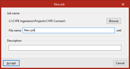
When you launch the app and click on "New", you are given the option to create a "New project". First, enter the "File name" and its "Description".
Selecting the work mode
In this step, you must select either "Project" or "Manufacturing" as the work mode.
Each of these work modes is designed for carrying out specific tasks, such as those specified in this link.
Project selection
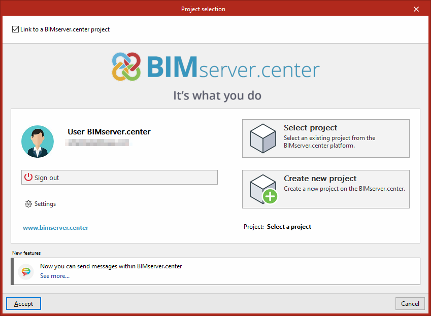
The project can then be integrated into an existing project on BIMserver.center.
This is done in the "Project selection" window, which offers the following options:
- On the left-hand side, you can sign in using a BIMserver.center account.
- On the right, the "Select project" option is used to choose an existing project. You also have the option to "Create a new project". In that case, the project you create will be visible on BIMserver.center from that point onwards.
- You can start the project without linking it to the BIMserver.center platform. To do this, simply untick the box labelled "Link to a BIMserver.center project", which is located in the top left-hand corner.
At any stage of the project, you can share or import project files via the "BIMserver.center" group, located in the top right-hand corner of the main interface on the "Model" or "Documents" tab.
Importing BIM models
If a project hosted on the BIMserver.center platform has been selected via "Select project", the "Import BIM models" window will then appear, displaying the files contained in that project in IFC format.
The app allows you to include one or more of the existing models in that project. To do this, tick the "Import" box and confirm.
In addition, in this window, the program offers the following options:
- Libraries
- Update the element and material libraries (optional)
When this option is enabled, the program will update the information in the element and material libraries based on the data read from the structural models imported from the BIM model, creating and assigning the corresponding types.
- Update the element and material libraries (optional)
- Nodes
- Import nodes (optional)
Using this option, the program automatically generates connections in their correct positions based on the connections in the structural models imported from the BIM model. The detailed definition of the connections must then be carried out using CYPE Connect's own tools.- Group nodes (optional)
If nodes are imported, this option allows them to be grouped automatically if they share the same characteristics.
- Group nodes (optional)
- Import nodes (optional)
- Geographical location and reference system
This allows you to open a dialog box to amend the model's geographical location and reference system.
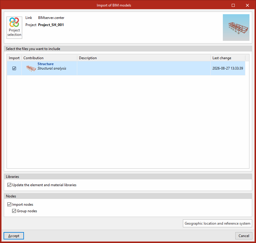
BIM model import wizard
This wizard appears when you have selected the option to import a BIM model and allows you to specify the elements you wish to import:
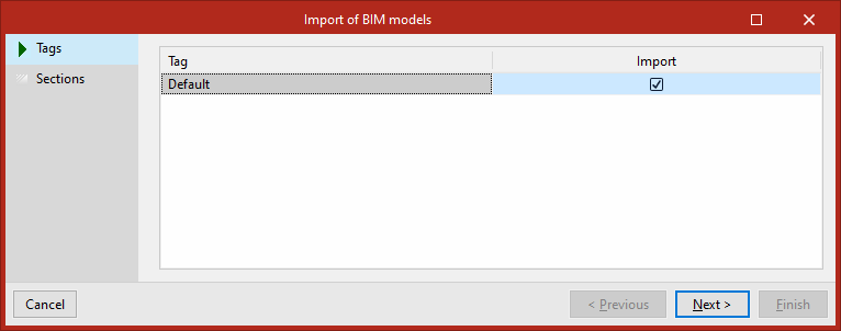
- Tags
This section of the wizard displays a list of the tags into which the BIM model is organised. You can tick the "Import" box next to each tag to import the elements associated with that tag.
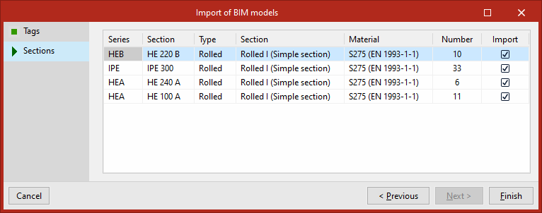
- Sections
This section of the wizard displays a list of section groups from the BIM model, showing their "Series", the specific "Section", and the "Material" of the profiles, as well as the "Number" of section in each group with these characteristics, which can be "Imported" by ticking the relevant box.
To complete the wizard, click on "Finish".
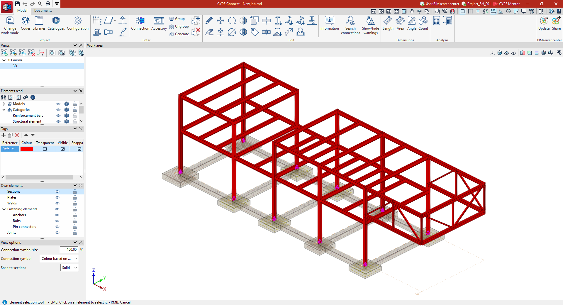
Import results
The program will open the main program interface on the "Model" tab.
The elements of the structural models that you have chosen to import will be displayed here, along with the automatically generated connections at the nodes. In addition, the necessary information will have been included in the element and material libraries, as well as the forces in the bars where applicable.
From this point onwards, users can add further elements, modify the imported elements, or continue working by defining and analysing connections, or by preparing the documents that can be generated from the model.
Importing structures from an XML file
From structural programs such as CYPE Connect, StruBIM Steel and StruBIM Shear Walls, structures saved in XML format files can be imported from other programs such as ETABS® or SAP2000®.
This file can be imported and used in CYPE programs in two alternative ways:
- Export the XML file to the BIMserver.center project using the separate program StruBIM Uploader.
In this case, when creating a new job from CYPE Connect, StruBIM Steel or StruBIM Shear Walls, it will be necessary to connect to that BIMserver.center project, and select and import the structural model exported from the StruBIM Uploader.
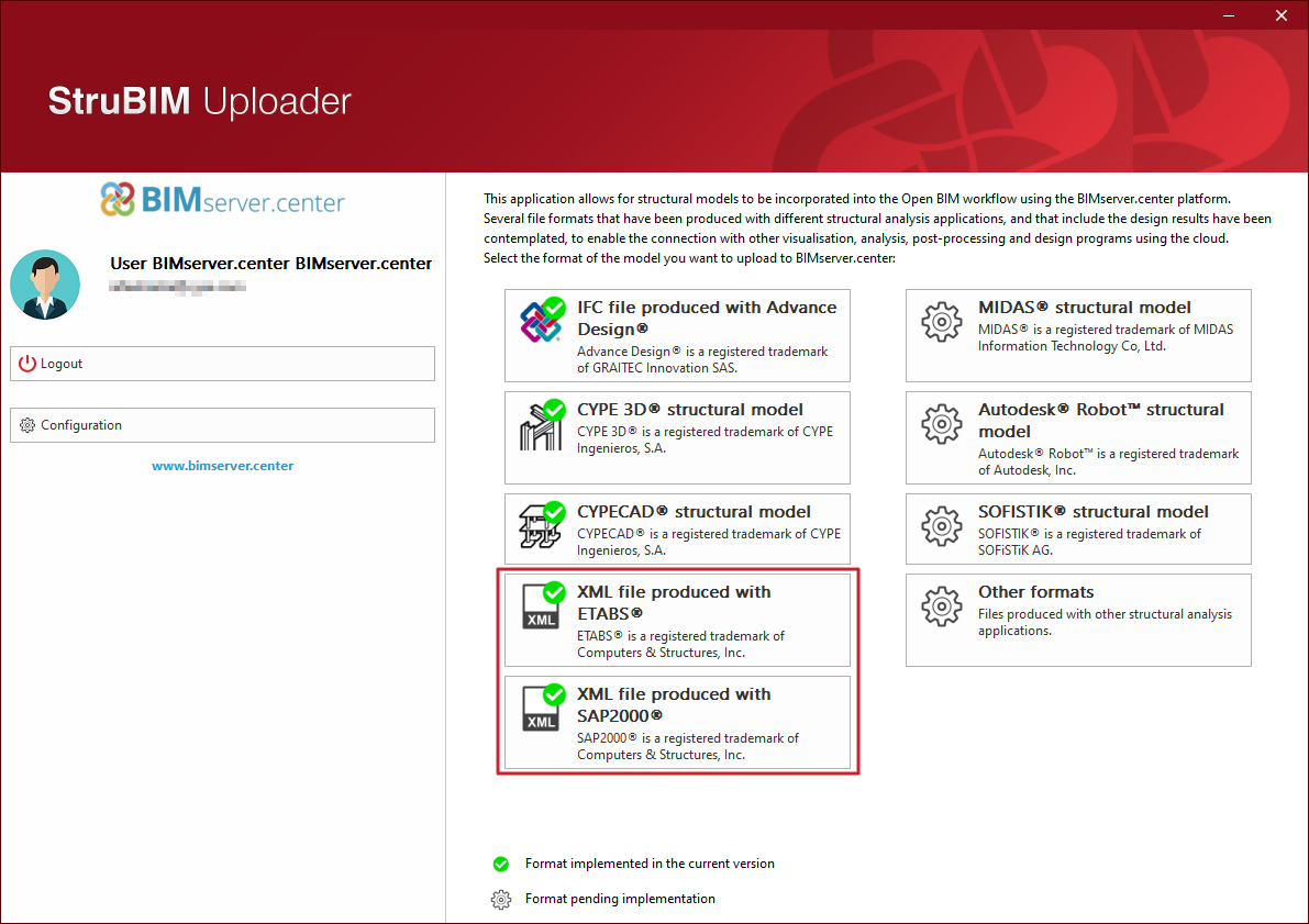
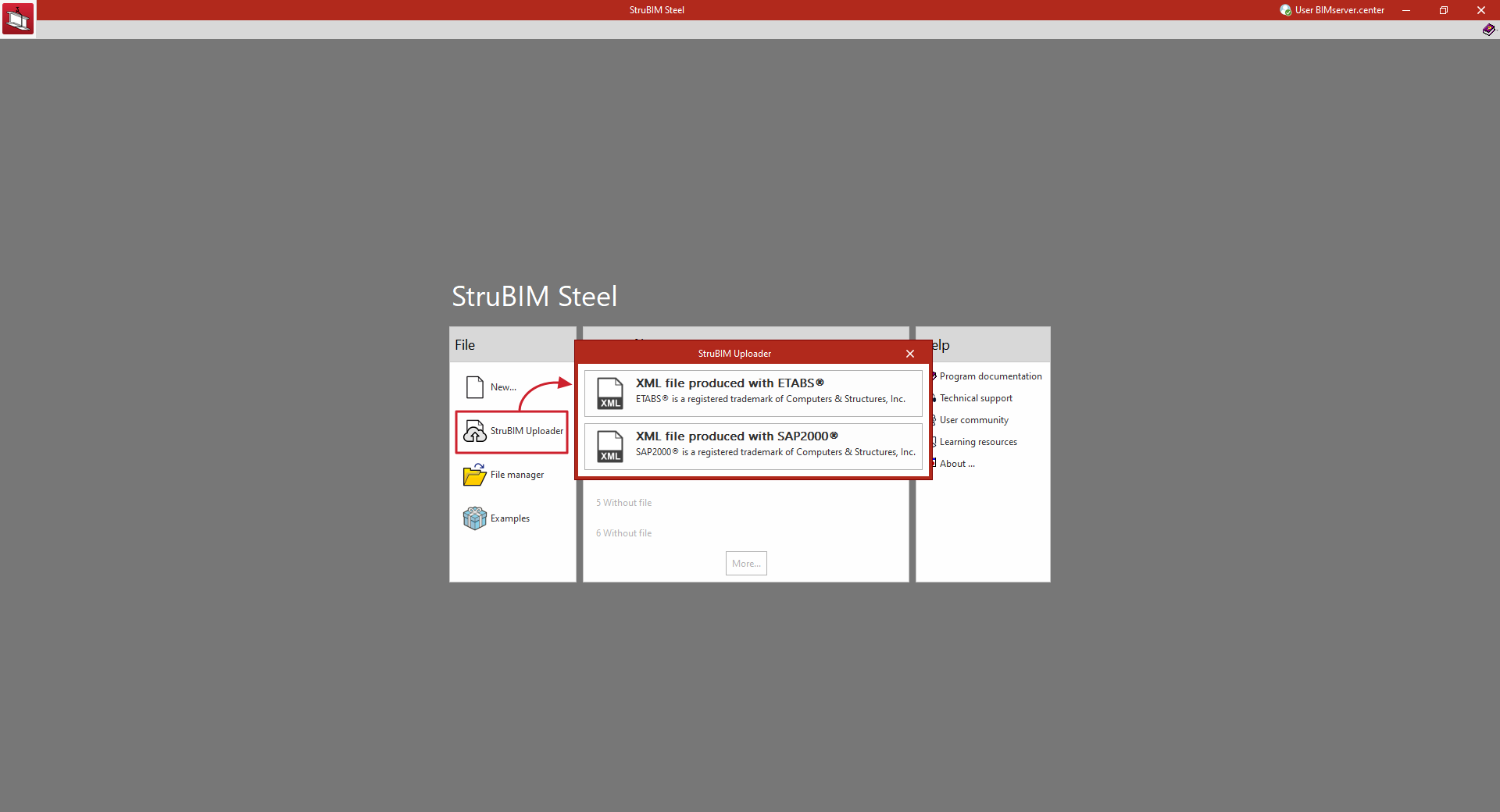
- By directly importing the XML file into CYPE Connect, StruBIM Steel or StruBIM Shear Walls programs, using the "StruBIM Uploader" option integrated in the program and available in the initial interface or in the "File" menu.
After creating a job, this option prompts the user to select a file in XML format from one of the available programs.
In doing so, the ETABS® or SAP2000® structural model is uploaded to an Open BIM project on the BIMserver.center platform (in the same way as the stand-alone "StruBIM Uploader" program would do) and, through an import process, obtains from it the information required to continue the work.
This eliminates the need to use the standalone StruBIM Uploader program.
Importing XML files produced by ETABS®
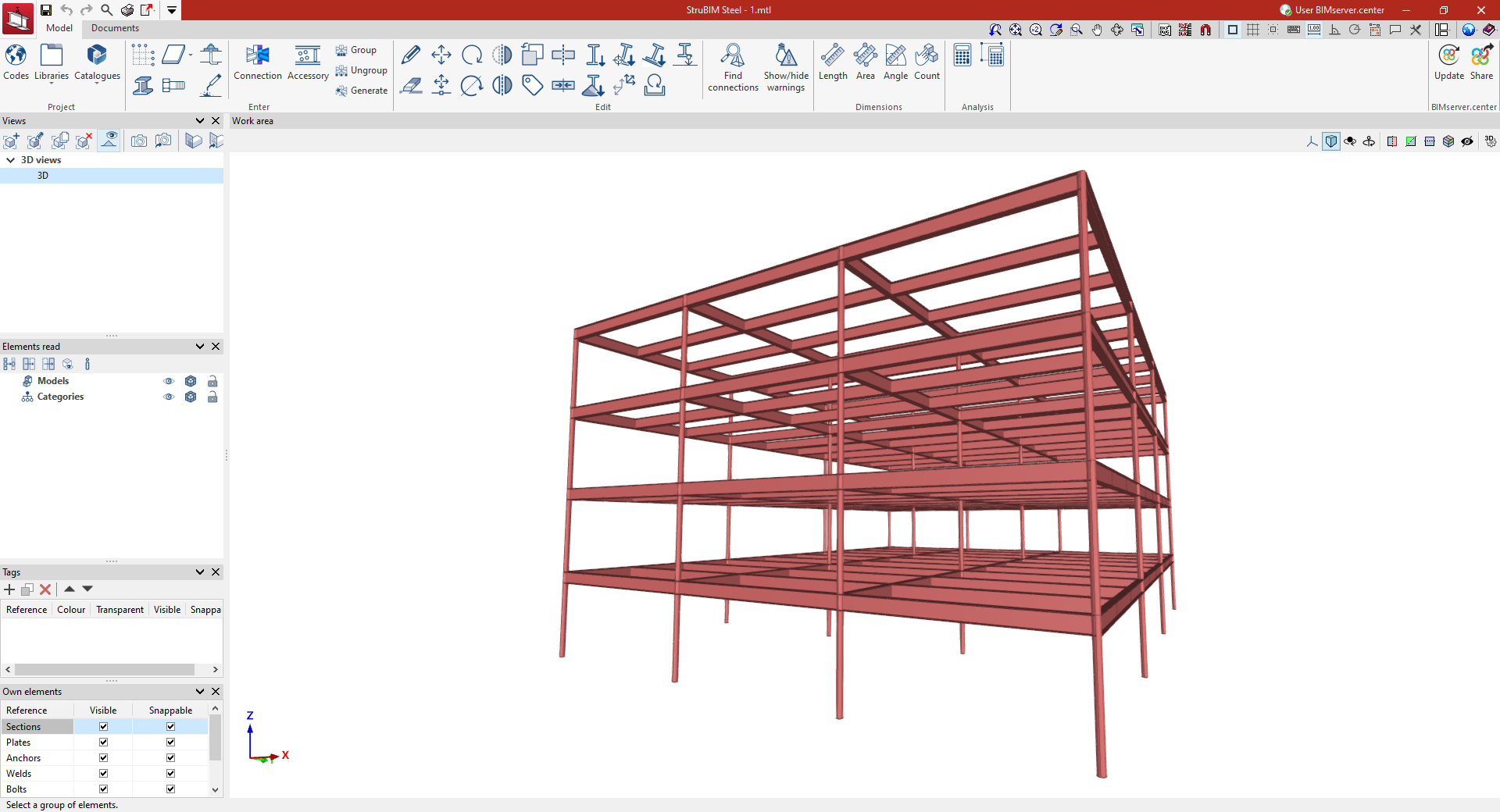
ETABS® is a registered trademark of Computer and Structures, Inc. The current implementation includes versions "ETABS 2016", "ETABS 18" and "ETABS 21". The following programs can import structures from an XML file generated by ETABS®:
- CYPE Connect
From the information contained in the ETABS® XML, the program imports the bars in the structure and their forces by combination. - StruBIM Steel
From the information contained in the ETABS® XML, the program imports the bars in the structure and their forces by combination. - StruBIM Shear Walls
From the information contained in the ETABS® XML, the program generates the necessary information to perform the shear wall design.
Importing XML files produced by SAP2000®
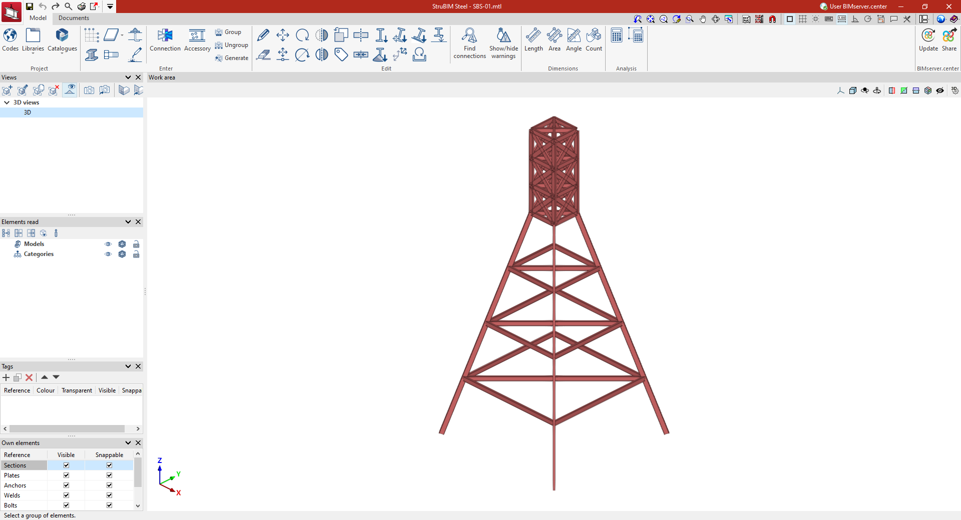
SAP2000® is a registered trademark of Computer and Structures, Inc. The following programs can import structures from an XML file generated by SAP2000®:
- CYPE Connect
From the information contained in the SAP2000® XML, the program imports the bars in the structure and their forces by combination. - StruBIM Steel
From the information contained in the SAP2000® XML, the program imports the bars in the structure and their forces by combination.
XML file export configuration
For import into CYPE Connect or StruBIM Steel, from ETABS® or SAP2000®, the XML file exported by these programs must contain all model definition tables and all bar force tables.
The export of all these tables can be activated from the export to XML file configuration options in the original program. For example, from the "Choose Tables for Export to XML File" option in ETABS®, the following options must be selected:
- Model definition tables:
- System Data
- Property Definition
- Load Pattern Definitions
- Other Definitions
- Load Case Definitions
- Connectivity Data
- Joint Assignments
- Frame Assignments
- Options and Preferences Data
- Miscellaneous Data
- Bar force tables ("ANALYSIS RESULTS" > "Element Output" > "Frame Output"):
- Table: Element Forces - Columns
- Table: Element Forces - Beams
- Table: Element Forces - Braces
- Table: Element Joint Forces - Frame
For SAP2000®, the tables read by the programs and which are necessary are the following (with the name given to them by SAP2000® in the XML file):
- Program_x0020_Control
- Joint_x0020_Coordinates
- Joint_x0020_Restraint_x0020_Assignments
- Material_x0020_Properties_x0020_02x0020-_x0020_Basic_x0020_Mechanical_x0020_Properties
- Material_x0020_Properties_x0020_03ax0020-_x0020_Steel_x0020_Data
- Material_x0020_Properties_x0020_03dx0020-_x0020_Cold_x0020_Formed_x0020_Data
- Connectivityx0020-_x0020_Frame
- Objects_x0020_And_x0020_Elementsx0020-_x0020_Frames
- Frame_x0020_Offset_x0020_Along_x0020_Length_x0020_Assignments
- Frame_x0020_Section_x0020_Assignments
- Frame_x0020_Local_x0020_Axes_x0020_Assignments_x0020_1x0020-_x0020_Typical
- Frame_x0020_Insertion_x0020_Point_x0020_Assignments
- Frame_x0020_Section_x0020_Properties_x0020_01x0020-_x0020_General
- Frame_x0020_Section_x0020_Properties_x0020_05x0020-_x0020_Nonprismatic
- Load_x0020_Pattern_x0020_Definitions
- Load_x0020_Case_x0020_Definitions
- Casex0020-_x0020_Static_x0020_1x0020-_x0020_Load_x0020_Assignments
- Casex0020-_x0020_Multistep_x0020_Static_x0020_1x0020-_x0020_Load_x0020_Assignments
- Casex0020-_x0020_Modal_x0020_2x0020-_x0020_Load_x0020_Assignmentsx0020-_x0020_Eigen
- Casex0020-_x0020_Modal_x0020_3x0020-_x0020_Load_x0020_Assignmentsx0020-_x0020_Ritz
- Casex0020-_x0020_Response_x0020_Spectrum_x0020_2x0020-_x0020_Load_x0020_Assignments
- Casex0020-_x0020_Modal_x0020_History_x0020_2x0020-_x0020_Load_x0020_Assignments
- Casex0020-_x0020_Direct_x0020_History_x0020_2x0020-_x0020_Load_x0020_Assignments
- Casex0020-_x0020_Frequency_x0020_History_x0020_2x0020-_x0020_Load_x0020_Assignments
- Casex0020-_x0020_Buckling_x0020_2x0020-_x0020_Load_x0020_Assignments
- Casex0020-_x0020_Power_x0020_Spectral_x0020_Density_x0020_2x0020-_x0020_Load_x0020_Assignments
- Casex0020-_x0020_Steady_x0020_State_x0020_2x0020-_x0020_Load_x0020_Assignments
- Combination_x0020_Definitions
- Element_x0020_Forcesx0020-_x0020_Frames
Some of these tables may not appear in the XML file, as they are not exported when empty. In this case, the tables could be optional.
Importing JSON files
The CYPE Connect and StruBIM Steel programs allow you to import bars and their forces from structural models defined in CYPE 3D, CYPECAD or third-party programs such as ETABS® or SAP2000®.
They also allow the import of structural models using JSON exchange files. This extends interoperability, allowing structural models defined and analysed in any other program to be imported.
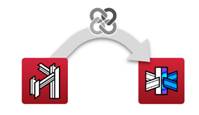
Workflow between CYPE 3D (or CYPECAD) and CYPE Connect (or StruBIM Steel)
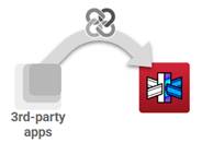
Workflow between third-party apps and CYPE Connect (or StruBIM Steel)
The exchange is carried out using two files: one mandatory file containing the model geometry, and another optional file containing the forces. The structure and syntax of both files are described in the Guide to JSON file specification for CYPE Connect and StruBIM Steel.
Communication with CYPE 3D or CYPECAD is achieved by exporting the structure to BIMserver and then importing it. Communication between external third-party apps and CYPE Connect or StruBIM Steel is also achieved through the BIMserver.center platform.
The exchange process consists of two stages: first, generating JSON files and, second, creating the contribution in BIMserver.center from these files.
1. Generation of exchange files
The exchange files may be generated directly from apps that implement the JSON format. This implementation may be carried out by the software manufacturer itself, by its users, or by third parties, provided that the app has an API.
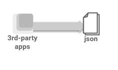
Direct generation of a JSON file from a third-party application
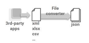
Generation of a JSON file using a converter, from files in other formats generated by third-party apps (XML, XSLX, CSV...)
2. Contribution to BIMserver.center
Option 1: Input from CYPE Connect or StruBIM Steel
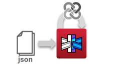
Contributions can be uploaded to the BIMserver.center project via CYPE Connect or StruBIM Steel, using the JSON exchange files generated during the initial phase. To do this, use the "StruBIM Uploader" tool, located in the "File" menu.
The contribution must include:
- The model's geometry file (required).
- The force file (optional).
Option 2: Direct contribution from the source app via the BIMserver.center REST API
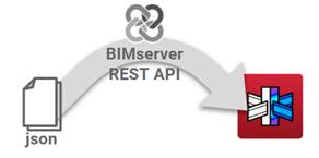
Once the JSON exchange files have been generated, either directly by the third-party app or by converting the original files, these exchange files can be sent to the project by integrating BIMserver through its API BIMserver.center REST API SwaggerUI (link to BIMserver.center REST API) This technology allows users to connect directly to BIMserver and export in the same way as CYPE 3D.
The contribution generated must include:
- The model geometry file, with extension .mgun, labelled as geometry_model_mef_connections_design (mandatory).
- The force file, with extension .mar3du, labelled as analytical_model_mef_connections_design (optional).
Integration in CYPE Connect or StruBIM Steel
Finally, these contributions can be imported from CYPE Connect or StruBIM Steel, either when creating a new project or when updating an existing project.
Table of contents
Complete your tour of CYPE Connect by exploring the other sections available:
