Part numbering
Part numbering is required to subsequently generate documents for the structural components. This is carried out using the tools in the "Numbering" group on the top toolbar, under the "Documents" tab of the program’s main interface.

Parts
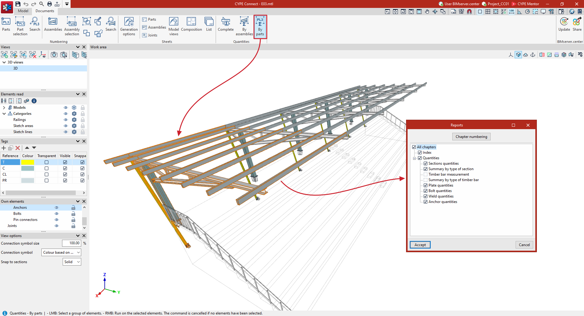
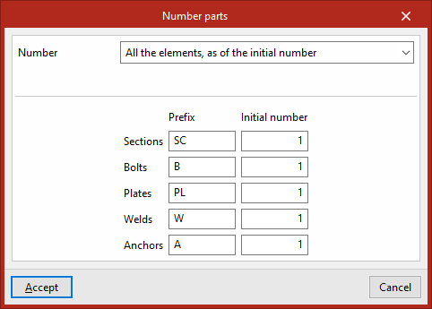
The first option available, "Parts", allows you to number all the parts of the model automatically. When you click on this option, the "Number parts" window appears.
The drop-down menu at the top lists the elements to be numbered. These may be:
- All elements, starting from the initial number.
- Only unnumbered elements, starting from the initial number.
- Only unnumbered elements, starting from the last number used.
At the bottom, enter the "Prefix" to be used for numbering each element, and specify the "Initial number" from which the numbering will begin. The elements include:
- Sections
- Bolts
- Plates
- Welds
- Anchors
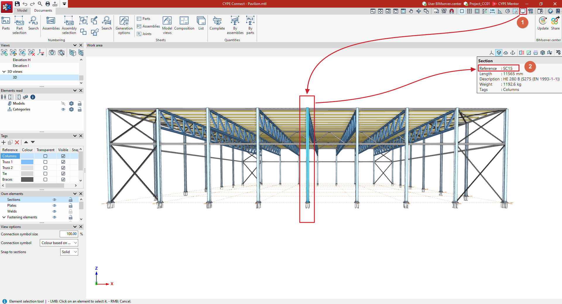
After clicking "Accept", the program numbers the parts of the model, compares elements, and applies the same numbering if they are identical.
| Note: |
|---|
| To view the part numbers, click the "Show information texts" button on the top bar and hover the pointer over each element in the viewer. The number for each part appears in the "Reference" field of the information text box. |
Part selection
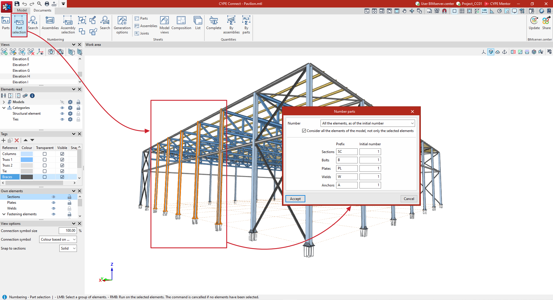
The second option in the group, "Part selection", can be used to number only those parts of the model you have selected.
After clicking on the option, select the parts to be numbered one by one using the left mouse button or by drawing a selection area. Then, click the right mouse button.
This brings up the "Number parts" window again, with the same options as those mentioned in the previous section ("Parts").
In addition, you can tick the box labelled "Consider all elements in the model, not just the selected ones" if you want the program to search the entire model for parts that are already numbered and match the selected ones. In that case, the same numbering will be applied to them.
If this option is disabled, numbering will be applied taking into account only the selected elements.
Finally, click "Accept".
Search
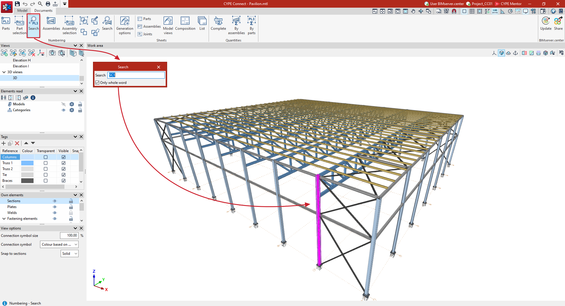
The "Search" option allows you to search for a part by entering the part reference text.
You can choose to search only for references consisting exactly of the word you are typing (by ticking the "Exact match" box) or for all references containing the text you are typing (by unticking that box).
The parts found will be highlighted in magenta on the model.
Assembly numbering
Numbering assemblies is necessary in order to subsequently generate the documentation for the structure’s assemblies; this is done using the tools in the "Numbering" group on the top toolbar, under the "Documents" tab of the program’s main interface.

Assemblies
Firstly, the "Assemblies" option allows you to number all the assemblies in the model automatically. Assemblies are groups of structural parts that are joined by bolts or welds carried out in the workshop.
After clicking on the option, the "Number assemblies" window appears.
The drop-down menu at the top lists the elements to be numbered. These may be:
- All elements, starting from the initial number
- Only unnumbered elements, starting from the initial number
- Only unnumbered elements, starting from the last number used
At the bottom, enter the "Prefix" to be used for numbering the assemblies and the "Starting number" from which the numbering will begin.
If required, you can tick the box at the bottom to "Assign a colour automatically" to each assembly.
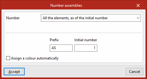
After clicking "Accept", the program numbers the model's assemblies, comparing the elements that make them up and applying the same numbering if they are identical.
| Note: |
|---|
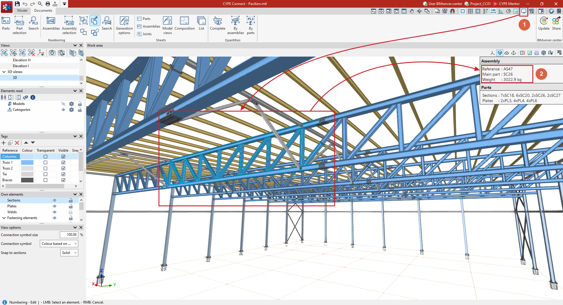
| To view the assembly numbers, click the "Show information texts" button on the top bar and, whilst any of the assembly numbering options remains selected, hover the pointer over each element in the viewer. The assembly number appears in the "Reference" field of the information text box. Its "Main part" is also specified. |
Assembly selection
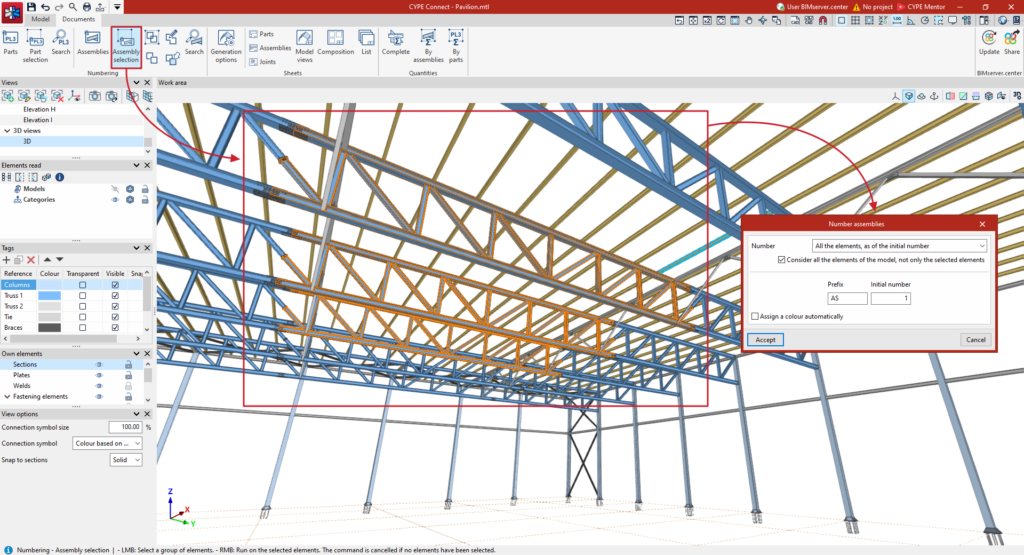
The next option, "Assembly selection", can be used to number only those assemblies in the model that you have selected.
After clicking on the option, select the assemblies to be numbered one by one using the left mouse button or by drawing a selection area. Then, click the right mouse button.
This brings up the "Number assemblies" window again, with the same options as those mentioned in the previous section ("Assemblies").
In addition, you can tick the box labelled "Consider all elements in the model, not just the selected ones" if you want the program to search the entire model for assemblies that are already numbered and match the selected ones; in that case, the same numbering will be applied to them.
If this option is disabled, numbering will be applied taking into account only the selected elements.
Next, click on "Accept".
Assign
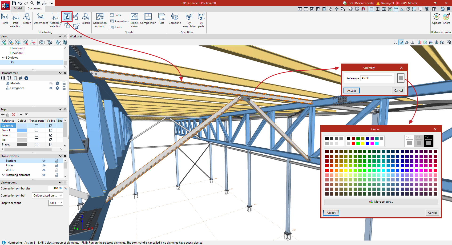
The "Assign" option allows you to create and number assemblies manually. After clicking on the option, select the elements that make up the new assembly one by one using the left mouse button, or use a selection area. Then, right-click.
In the "Assemblies" window that appears, you can enter your "Reference" and assign a "Colour", before finally clicking "Accept".
Ungroup
The "Ungroup" option allows you to ungroup assemblies that have been grouped manually.
To do this, click on the option and then select the groups you wish to ungroup using the left mouse button. Next, click the right mouse button.
Edit
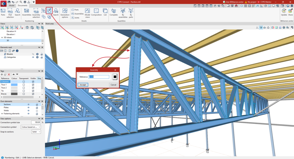
Using "Edit", you can edit the numbering of an assembly. Similarly, click on the option and then left-click on the assembly you wish to renumber. In the "Assemblies" window, change the "Reference" and "Colour" if necessary, then click “Accept”.
Assign main part
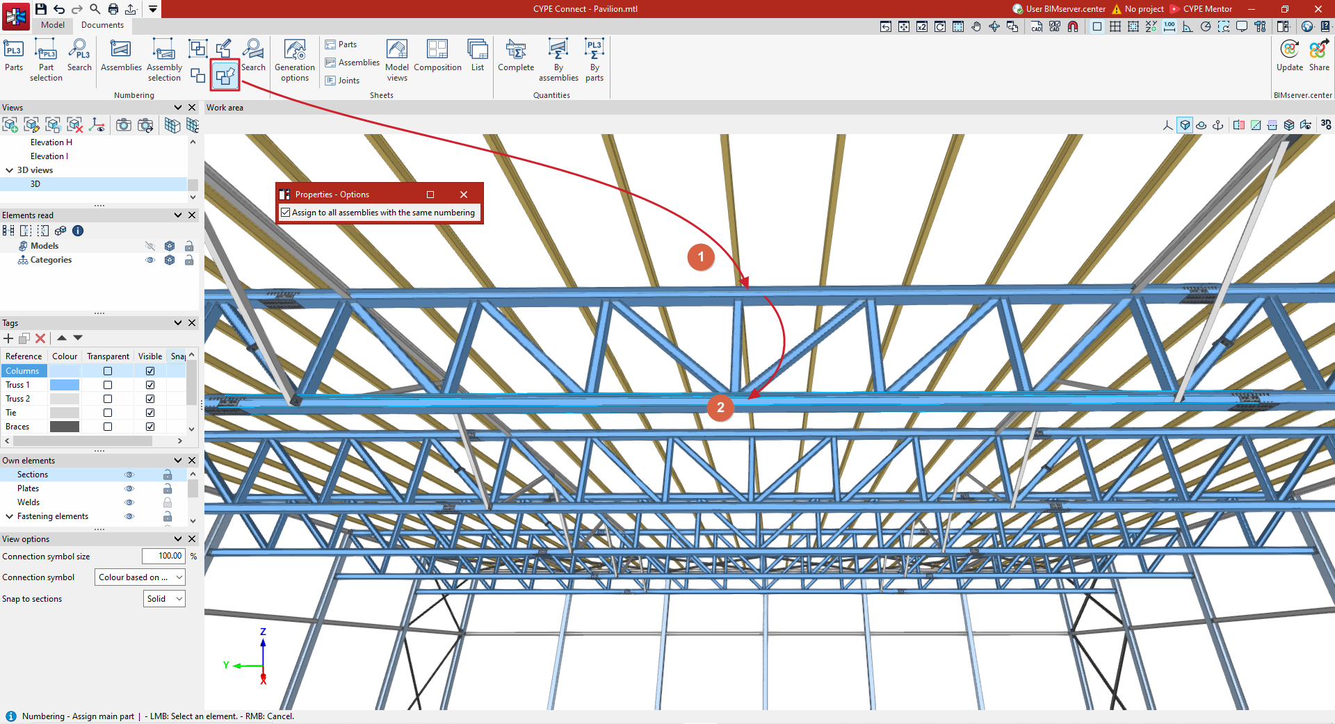
Finally, there is an option to "Assign the main part" to a group.
The main part of an assembly is used in its reference and to define the orientation of the main views in the assembly drawings.
After selecting the option, use the left mouse button to highlight the assembly in the viewport and then the part you wish to designate as the main one. In the "Properties – Options" window that appears, you can specify whether you wish to "Assign to all assemblies with the same numbering".
Search
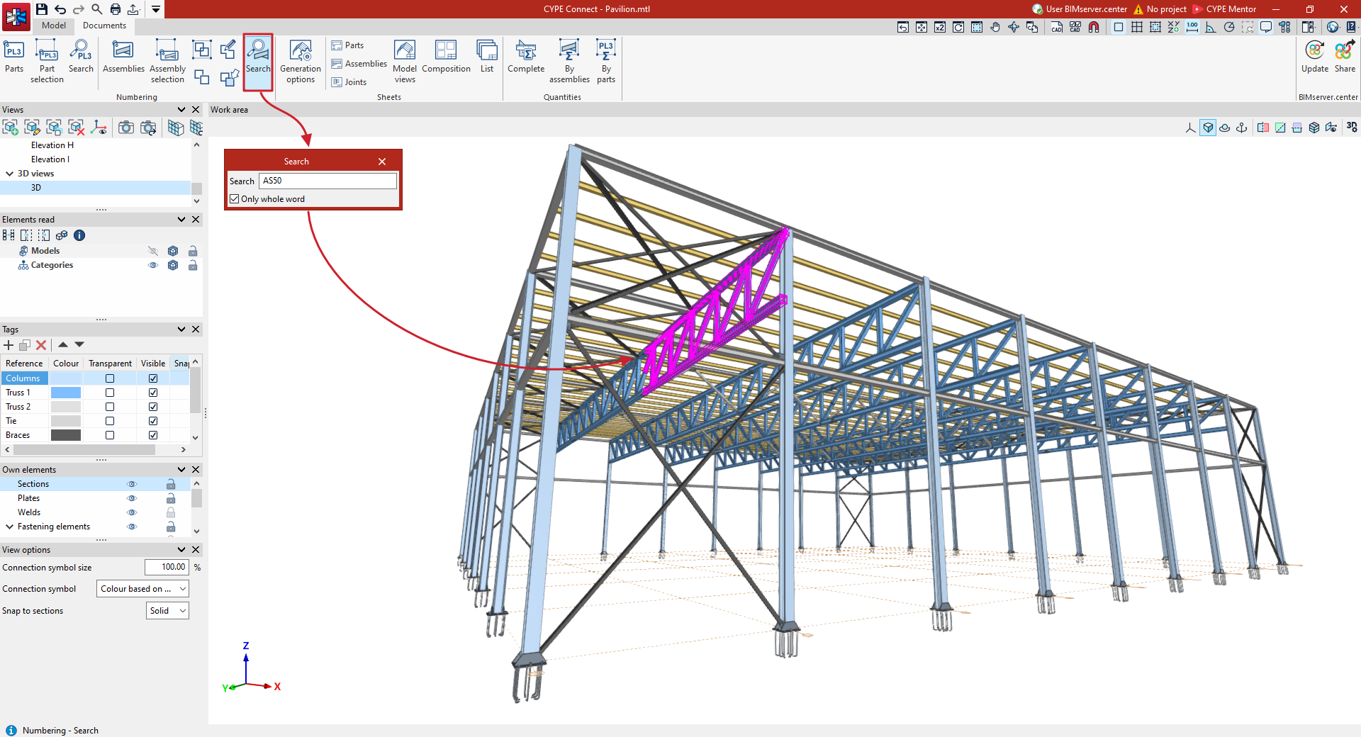
The "Search" option allows you to search for an assembly by entering the assembly’s reference text.
You can choose to search only for references consisting exactly of the word you are typing (by ticking the "Only whole word" box) or for all references containing the text you are typing (by unticking that box).
The assemblies found will be highlighted in magenta in the model.
Sheet generation options
The sheet generation options can be configured by clicking on the "Generation options" button in the "Sheets" section of the top toolbar, within the "Documents" tab of the program’s main interface.

Generation options
The "Generation options" are organised into a dialog box with four tabs, which allow you to control the "Parts", "Assemblies", "Joints" and "Model views" sheets. Some of these options are common to all tabs, whilst others are specific to each tab.
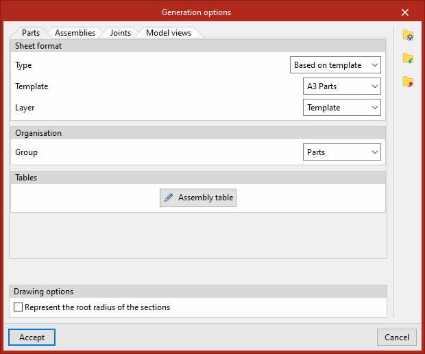
"Parts" tab
Firstly, under "Sheet format", select the format and template you wish to use to start new parts sheets. Under "Type", you can select "Empty", and then choose the sheet "Format" directly, or select "Based on template". In this case, you select a previously created library "Template" – which already has a specific sheet format associated with it – and the "Layer" onto which it will be loaded.
Further down, under "Organisation", select the sheet group to which the newly created part sheets will belong. By default, the "Part drawings", "Assembly drawings", "Joint drawings" and "Structure drawings" groups are available, but these can be modified by the user.
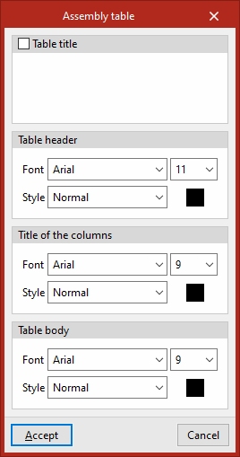
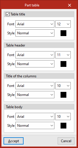
Next, in the "Tables" section, available under the "Parts" and "Assemblies" tabs, you can manage the "Font" and "Style" of the text in the predefined tables, including the "Table title" and "Table header", the "Column headings" and the "Table body".
At the bottom, under the "Drawing options" section, you can tick the box to "Represent the root radius of the sections". By default, this option is unticked.
"Assemblies" tab
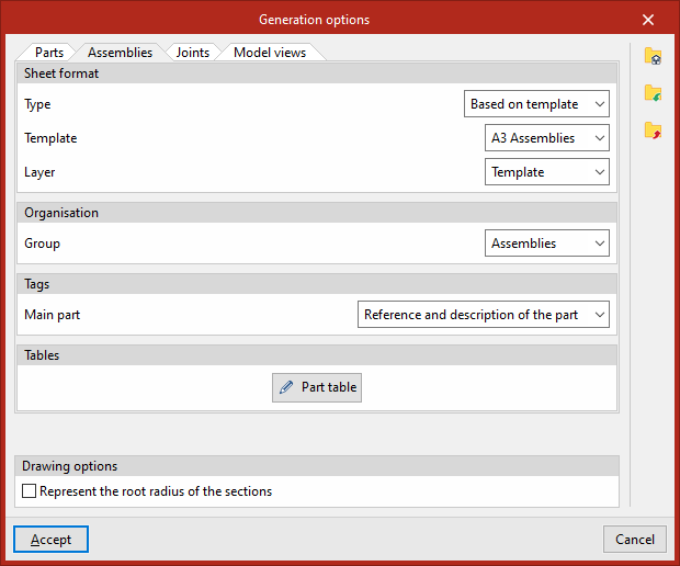
In the "Assemblies" tab, under "Sheet format", you can select the format and template you wish to use when creating new assembly sheets. Under "Type", you can select "Empty" and then choose the sheet "Format" directly, or select "From template". In this case, you select a previously created library "Template" – which already has a specific sheet format associated with it – and the "Layer" onto which it will be loaded.
Further down, under "Organisation", select the sheet group to which the newly created assembly sheets will belong. By default, the groups "Part drawings", "Assembly drawings", "Joint drawings" and "Structure drawings" are available, but these can be modified by the user.
In addition, there is a specific option here for editing the information that will appear in the automatic "Tags" in the main section of the assemblies. You can choose to display only the "Description", only the "Part number", or both the "Part number" and "Description" simultaneously.
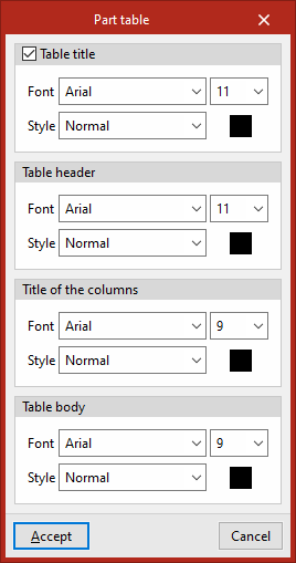
Next, in the "Tables" section, available under the "Parts" and "Assemblies" tabs, you can manage the "Font" and "Style" of the text in the predefined tables, including the "Table title" and "Table header", the "Title of the columns" and the "Table body".
At the bottom, under the "Drawing options" section, you can tick the box to "Represent the root radius of the sections". By default, this option is unticked.
"Joints" tab
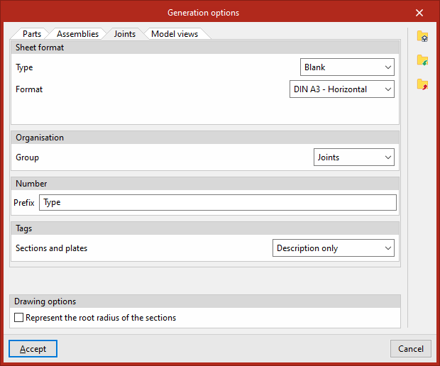
On the "Joints" tab, under "Sheet format", you can select the format and template you wish to use when creating new joint sheets. Under "Type", you can select "Empty", and then choose the sheet "Format" directly, or select "From template". In this case, you select a previously created library "Template" – which already has a specific sheet format associated with it – and the "Layer" onto which it will be loaded.
Further down, under "Organisation", select the sheet group to which the newly created joint sheets will belong. By default, the groups "Part drawings", "Assembly drawings", "Joint drawings" and "Structural drawings" are available, but these can be modified by the user.
There is also a specific field here where you can enter the "Prefix" that the program will use to "Number" the joints.
Furthermore, you can control the information that appears in the automatic "Tags" for "Sections and plates", specifying whether you want the "Reference and description" or "Description only" for these elements to be displayed.
At the bottom, under the "Drawing options" section, you can tick the box for "Represent the root radius of the sections". By default, this option is unticked.
"Model views" tab
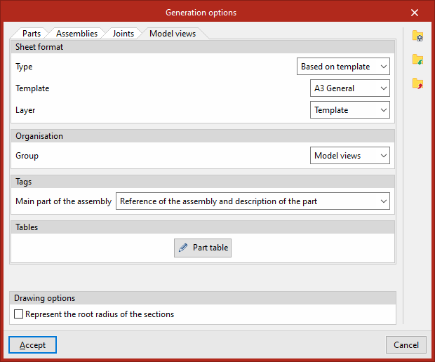
On the "Model views" tab, under "Sheet format", you can select the format and template you wish to use when creating new model view sheets. Under "Type", you can select "Empty" to then choose the sheet "Format" directly, or "From template". In this case, you select a previously created library "Template" – which already has a specific sheet format associated with it – and the "Layer" onto which it will be loaded.
Further down, under "Organisation", select the sheet group to which the new model view sheets will belong. By default, the groups "Part drawings", "Assembly drawings", "Joint drawings" and "Structural drawings" are available, but these can be modified by the user.
The information displayed in the "Tags" of the "Main part of the assembly" can also be configured. This may include:
- Only the "Description"
- The "Assembly reference"
- The "Reference to the whole and the part"
- The "Reference of the assembly and description of the part"
- Or the "Assembly reference and the part reference and description"
Next, in the "Tables" section, available under the "Parts" and "Assemblies" tabs, you can manage the "Font" and "Style" of the text in the predefined tables, including the "Table title" and "Table header", the "Column headings" and the "Table body".
At the bottom, under the "Drawing options" section, you can tick the box to "Represent the root radius of the sections". By default, this option is unticked.
Data export and import options
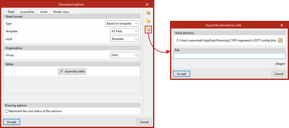
Finally, if you wish to save the settings for the sheet generation options to files on the hard drive, use the buttons on the right-hand side.
The "Export" option is used to save library information to a specific file. The libraries saved in a file can then be "Imported" into any project.
You can also carry out a "File selection with initial values for the creation of a new job". This way, when creating a new project, the program will automatically load the drawing generation options from the selected files.
Finally, to apply the changes, click "Accept".
Part sheets
The part sheets show only one element – either a section or a plate – and graphically document its geometry.
Part drawings are created from the "Documents" tab in the program's main interface by clicking on the "Parts" button in the "Drawings" section of the top toolbar.

Parts
The parts of the structure must be numbered to use this tool; if they are not, the program will start the "Numbering" process when this option is selected.
Next, select the part in the model by left-clicking on it. This opens the "Edit sheets" window:
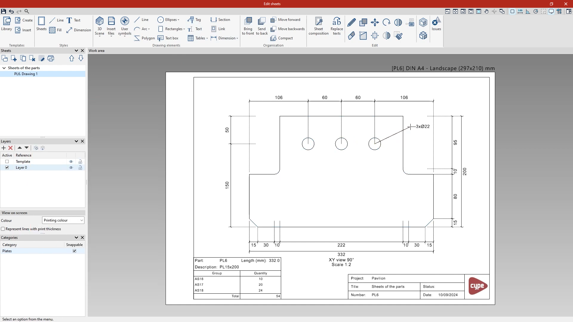
This sheet editing interface is shared across several CYPE programs and offers similar options:
- On the left-hand side, in the "Sheets" section, you can see that the program has generated a drawing with the part’s name, linked to the "Sheets of the parts" group if this has been specified in the "Generation options" in the "Documents" tab. If required, you can create and edit further sheets here to document the selected part.
- Next, in the "Layers" section, you can view the layer created to contain the "Template" – which may include the text box – as well as the active editing layer. If necessary, you can create and edit further layers, as well as manage their "View on screen".
- Further down, in the "Categories" section, you can specify whether each of the categories of elements displayed on the sheets is "Snappable" or not.
To add information to the selected sheet, use the tools in the top toolbar. Here you’ll find options for managing "Templates" and "Styles", adding "Drawing elements" to each sheet – such as "Lines" and "Text" – as well as "Organisation" and "Editing" tools.
Among the most useful are the following:
- In the "Drawing elements" pane, from the "3D scene" menu, you can "Insert" views manually or select "Insert predefined views" to have the program automatically generate a set of views of the selected part.
- If you choose this last option, the window that appears allows you to control the "Appearance", the "View titles" and their "Dimensions", select the "Views to be generated" and manage the "Sheets" into which they are inserted.
- You can also open the "Tables" menu to "Insert a predefined table". In this case, it is a "Table displaying the use of the part in the assemblies". The program can include this type of table in the sheet template.
- The "Tag" option, on the other hand, allows you to generate information automatically by selecting elements in the inserted views.
- The "Design" options include tools that allow you to select points on the elements in the view to measure their distance, area or the angle they form.
- In the "Edit" section, the options available include "Edit" to modify any of the graphic elements on the page, as well as "Move" to reposition them or "Delete".
Finally, in the "Sheets" section, the program offers an option to "Print" the desired sheets. In the window that appears when you click on this option, when you select the "Printer", you can choose to save a "PDF", "DXF" or "DWG" file, or print directly.
Once you have finished editing the sheets for the part, you can "Save" and close the window.
Assembly drawings
Assembly drawings provide a graphical representation of assemblies and show all the components required for their assembly in the workshop, whether these are sections, plates, welds, bolts or anchors.
Assembly drawings are created from the "Document" tab in the program's main interface by clicking on the "Assemblies" button in the "Drawings" section of the top toolbar.

Assemblies
The structural assemblies must be numbered to use this tool; if they are not, the program will start the "Numbering" process.
Next, select the assembly in the model by left-clicking on it. This opens the "Edit layers" window:
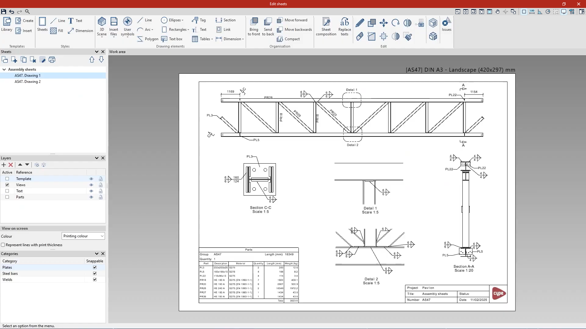
This sheet editing interface is shared across several CYPE programs and offers similar options:
- On the left-hand side, in the "Sheets" section, you can see that the program has generated a drawing with the part’s name, linked to the "Sheets of the parts" group if this has been specified in the "Generation options" in the "Documents" tab. If required, you can create and edit further sheets here to document the selected part.
- Next, in the "Layers" section, you can view the layer created to contain the "Template" – which may include the text box – as well as the active editing layer. If necessary, you can create and edit further layers, as well as manage their "View on screen".
- Further down, in the "Categories" section, you can specify whether each of the categories of elements displayed on the sheets is "Snappable" or not.
To add information to the selected sheet, use the tools in the top toolbar. Here you’ll find options for managing "Templates" and "Styles", adding "Drawing elements" to each sheet – such as "Lines" and "Text" – as well as "Organisation" and "Editing" tools.
Among the most useful are the following:
- In the "Drawing elements" pane, from the "3D scene" menu, you can "Insert" views manually or select "Insert predefined views" to have the program automatically generate a set of views of the selected part.
- If you choose this last option, the window that appears allows you to control the "Appearance", the "View titles" and their "Dimensions", select the "Views to be generated" and manage the "Sheets" into which they are inserted.
- You can also open the "Tables" menu to "Insert a predefined table". In this case, it is a "Table displaying the use of the part in the assemblies". The program can include this type of table in the sheet template.
- The "Tag" option, on the other hand, allows you to generate information automatically by selecting elements in the inserted views.
- The "Design" options include tools that allow you to select points on the elements in the view to measure their distance, area or the angle they form.
- In the "Edit" section, the options available include "Edit" to modify any of the graphic elements on the page, as well as "Move" to reposition them or "Delete".
Finally, in the "Sheets" section, the program offers an option to "Print" the desired sheets. In the window that appears when you click on this option, when you select the "Printer", you can choose to save a "PDF", "DXF" or "DWG" file, or print directly.
Once you have finished editing the sheets for the part, you can "Save" and close the window.
Joint drawings
Joint drawings are generated from the data entered during the modelling stage, enabling detailed documentation of each joint.
To access the joint drawings, you can use a number of tools:
- One option is to go to the "Model" tab in the program’s main interface and, from there, select the "Joint" or "Fitting" option from the "Enter" section of the top toolbar, which allows you to create a new joint or fitting, or click the "Edit" option in the "Edit" section to edit an existing joint or fitting. This takes you to the joint editor, which, via various tabs, allows you to define the "Model" for each joint, carry out the "Analysis" and regulatory checks where applicable, and, finally, compile the "Sheets" associated with the joint.
- Alternatively, you can go to the "Documents" tab in the program's main interface and click on the "Joints" button in the "Sheets" section. Then, select the joint in the model by left-clicking on it.

Joints
When you click on this option and select the joint, the "Edit sheets" window opens, creating the joint sheets if they did not already exist or allowing you to edit the sheets that have already been created.
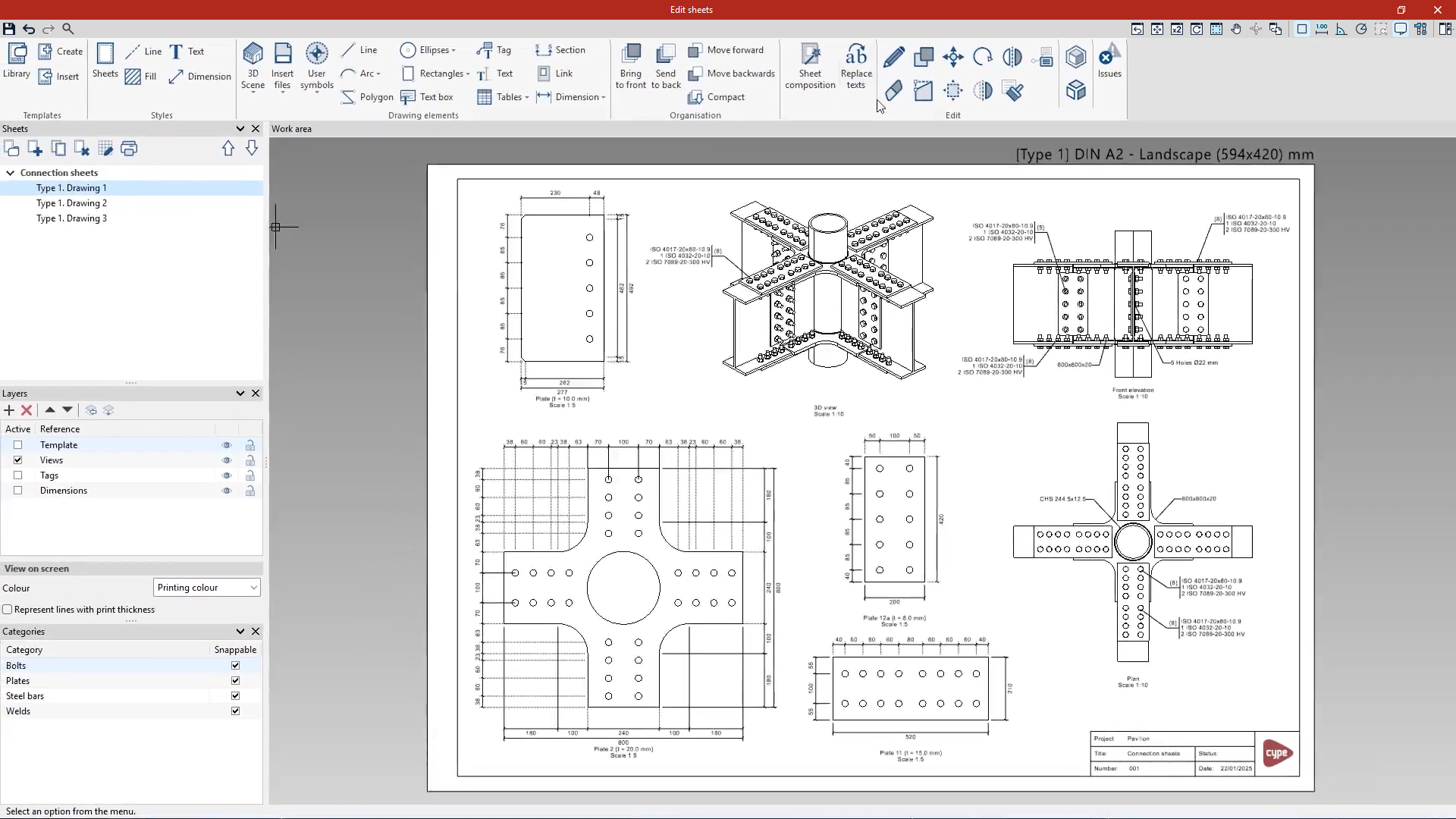
This sheet editing interface is shared across several CYPE programs and offers similar options:
- On the left-hand side, in the "Sheets" section, you can see that the program has generated a drawing with the part’s name, linked to the "Sheets of the parts" group if this has been specified in the "Generation options" in the "Documents" tab. If required, you can create and edit further sheets here to document the selected part.
- Next, in the "Layers" section, you can view the layer created to contain the "Template" – which may include the text box – as well as the active editing layer. If necessary, you can create and edit further layers, as well as manage their "View on screen".
- Further down, in the "Categories" section, you can specify whether each of the categories of elements displayed on the sheets is "Snappable" or not.
To add information to the selected slide, use the tools on the top toolbar. Here you’ll find options for managing "Templates" and "Styles", adding "Drawing elements" to each sheet – such as "Lines" and "Text" – as well as "Organisation" and "Editing" tools.
Among the most useful are the following.
- In the "Drawing elements" group, from the "3D scene" menu, you can "Insert" views manually or select "Insert predefined views" to have the program automatically generate a set of views of the selected part.
- If you choose this last option, the window that appears allows you to control the "Appearance", the "Title of the views" and their "Dimensions", select the "Views to be generated" and manage the "Sheets" into which they are inserted.
- The "Tag" option, on the other hand, allows you to generate information automatically by selecting elements in the inserted views.
- The "Design" options include tools that allow you to select points on the elements in the view to measure their distance, area or the angle they form.
- In the "Edit" section, the options available include "Edit" to modify any of the graphic elements on the page, as well as "Move" to reposition them or "Delete".
Finally, in the "Sheets" section, the program offers an option to "Print" the desired sheets. In the window that appears when you click on this option, when you select the "Printer", you can choose to save a "PDF", "DXF" or "DWG" file, or print directly.
Once you have finished editing the sheets for the part, you can "Save" and close the window.
Model view sheets
Model view sheets provide graphical documentation of the model developed in the program through a range of views, such as elevations, sections and plans, showing the complete structure.
Model view sheets are created from the "Documentation" tab in the program’s main interface by clicking on the "Model views" button in the "Sheets" section of the top toolbar.

Model views
The parts and assemblies of the structure must be numbered to use this tool; if they are not, the program initiates the "Numbering" process.
The "Edit sheets" window then opens.
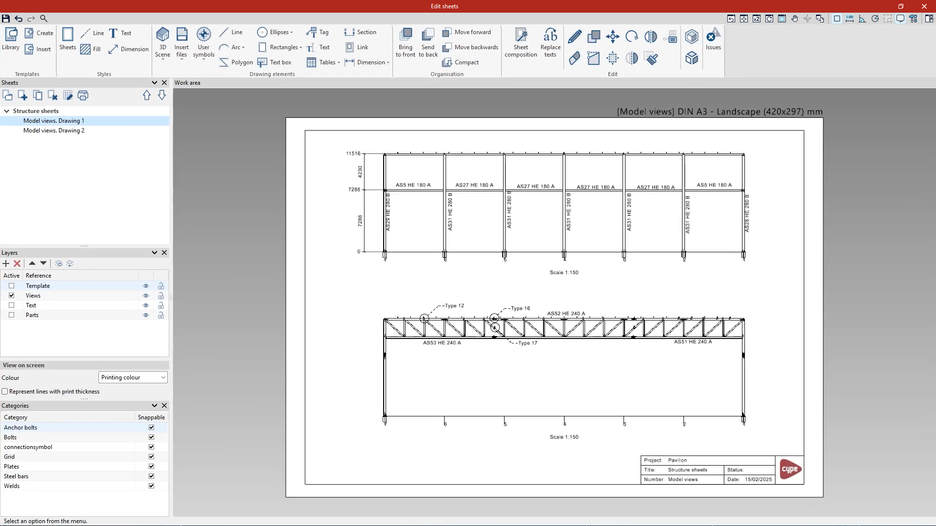
This sheet editing interface is shared across several CYPE programmes and offers similar options:
- On the left-hand side, in the "Sheets" section, you can see that the program has generated a drawing with the part’s name, linked to the "Sheets of the parts" group if this has been specified in the "Generation options" in the "Documents" tab. If required, you can create and edit further sheets here to document the selected part.
- Next, in the "Layers" section, you can view the layer created to contain the "Template" – which may include the text box – as well as the active editing layer. If necessary, you can create and edit further layers, as well as manage their "View on screen".
- Further down, in the "Categories" section, you can specify whether each of the categories of elements displayed on the sheets is "Snappable" or not.
To add information to the selected slide, use the tools on the top toolbar. Here you’ll find options for managing ‘Templates’ and ‘Styles’, adding ‘Drawing Elements’ to each sheet – such as ‘Lines’ and ‘Text’ – as well as ‘Organisation’ and ‘Editing’ tools.
Among the most useful are the following.
- In the "Drawing elements" pane, from the "3D scene" menu, you can "Insert" views manually or select "Insert predefined views" to have the program automatically generate a set of views of the selected part.
- If you choose this last option, the window that appears allows you to control the "Appearance", the "View titles" and their "Dimensions", select the "Views to be generated" and manage the "Sheets" into which they are inserted.
- The "Tag" option, on the other hand, allows you to generate information automatically by selecting elements in the inserted views.
- To tag parts and assemblies, after adjusting the "Properties" of the tag in the window that appears, select the element directly in the desired view and then position the tag. The program will display the assembly reference and, for the main parts, the part reference and description, depending on the options previously specified.
- To tag the position of the joints, you can make only their symbols "Snappable" by ticking the relevant box ("Connection symbol") and unticking the rest. You can also adjust the "Properties" of the tag, such as the representation of the line’s initial "Endpoint". Then, click on the joint and position the tag.
- The "Design" options include tools that allow you to select points on the elements in the view to measure their distance, area or the angle they form.
- In the "Edit" section, the options available include "Edit" to modify any of the graphic elements on the page, as well as "Move" to reposition them or "Delete".
Finally, in the "Sheets" section, the program offers an option to "Print" the desired sheets. In the window that appears when you click on this option, when you select the "Printer", you can choose to save a "PDF", "DXF" or "DWG" file, or print directly.
Once you have finished editing the sheets for the part, you can "Save" and close the window.
List of sheets
The list of sheets is managed in the "Documents" tab of the program’s main interface by clicking on the "Lists" option in the "Sheets" section of the top toolbar.

List
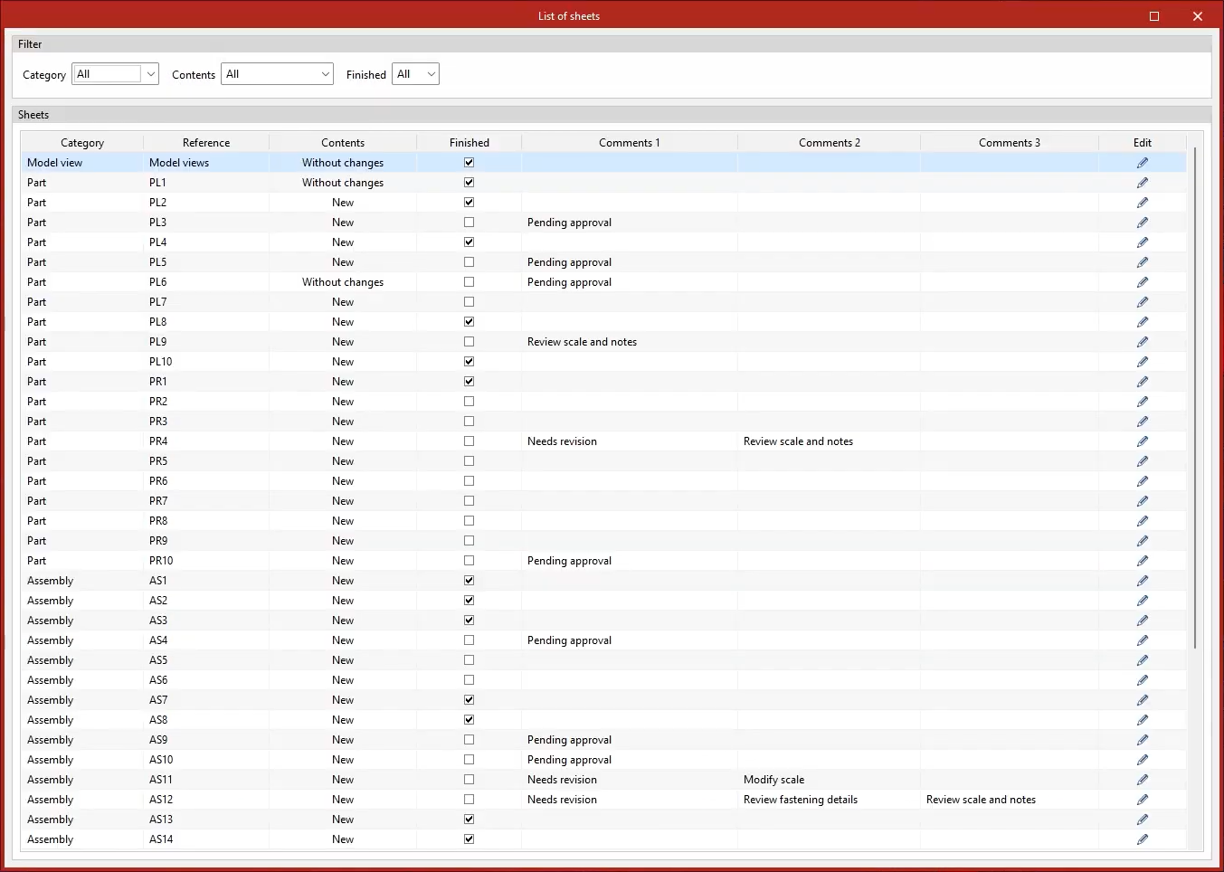
Clicking on this option opens the "List of sheets" window, which displays a list of all the sheets in the structure.
At the top, you can apply "Filters" to the list of drawings by "Category", if you wish to view only drawings for "Parts", "Assemblies", "Joints" or "Model views"; by their "Content" type, whether "New", "Duplicate", "Modified" or "Unchanged"; and by their completion status.
Next, the "Sheets" list shows the "Category" of each sheet, its "Reference" and the type of "Content".
The checkbox in the "Completed" column can be selected to mark each drawing as completed when appropriate.
The "Comment 1", "Comment 2" and "Comment 3" columns allow you to add notes or comments to each sheet.
Finally, from the list, you can access the content of each sheet by clicking on the "Edit" button in the right-hand column. This opens the editing interface for each sheet, allowing you to work on it directly.
Quantities reports
Quantities reports can be generated for the structural elements within the program.
To do this, go to the "Documents" tab in the program’s main interface and use the tools in the "Quantities" section of the top toolbar. The elements must be numbered to use these tools.

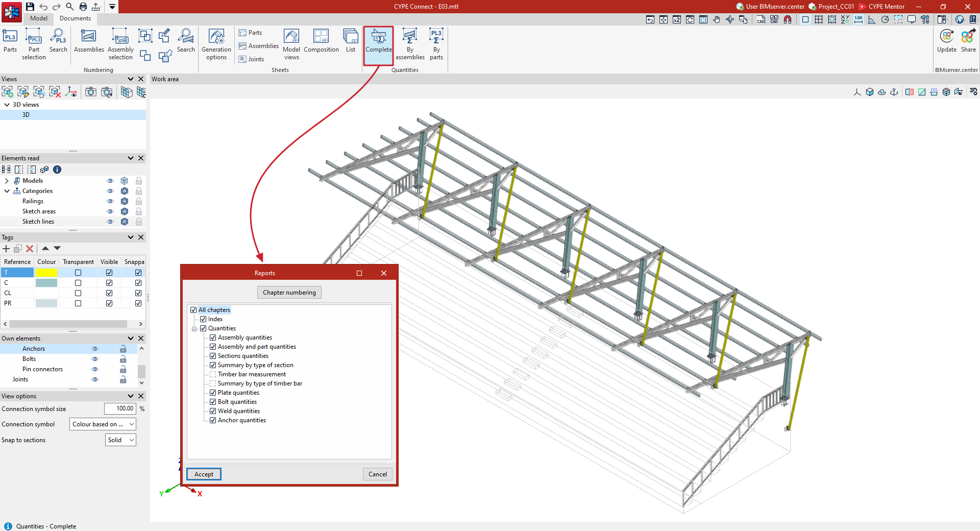
Complete
This option generates a "Complete" quantities report for the entire structure.
In the "Reports" window that appears, tick the relevant boxes to print "All chapters" or only the selected chapters.
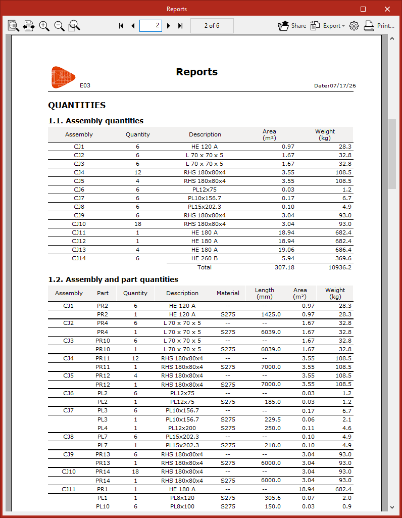
After clicking "Accept", the program will display a preview of the quantities report on the screen.
This report may include the tables for "Assembly quantities", "Assemblies and part quantities" and "Sections", a "Summary by type of section", containing data such as "Length", "Area" and "Weight", as well as the dimensions of plates, bolts, welds and anchors.
From here, using the options at the top, you can "Share" and "Export" the information in various formats, and "Print" the document directly.
By assemblies
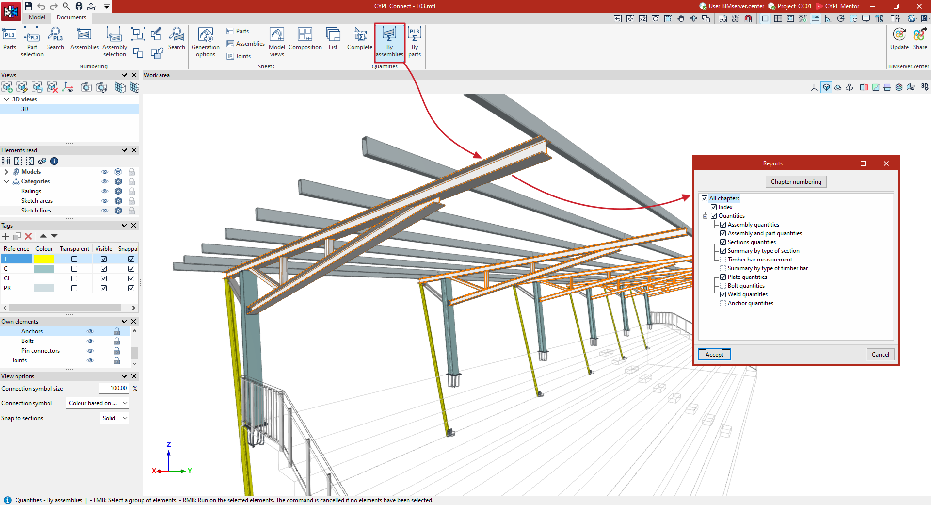
The "By assemblies" option allows you to generate a quantities list for a selection of assemblies within the structure.
In this case, after clicking on the option, you select the assemblies one by one using the left mouse button or use a selection area, and then click the right mouse button.
This brings up the "Reports" window again, which allows you to generate the available quantities for the selected assemblies.
Step by step
The "By parts" option allows you to generate a quantities list for a selection of parts of the structure.
Similarly, after clicking on the option, select the parts one by one or using a selection area, then right-click.
In the "Reports" window, you can include "Sections quantities", "Summary by type of section" and quantities of other elements such as plates, bolts, welds and anchors, if these have been selected.