

Part sheets
The part sheets show only one element – either a section or a plate – and graphically document its geometry.
Part drawings are created from the "Documents" tab in the program's main interface by clicking on the "Parts" button in the "Drawings" section of the top toolbar.

Parts
The parts of the structure must be numbered to use this tool; if they are not, the program will start the "Numbering" process when this option is selected.
Next, select the part in the model by left-clicking on it. This opens the "Edit sheets" window:
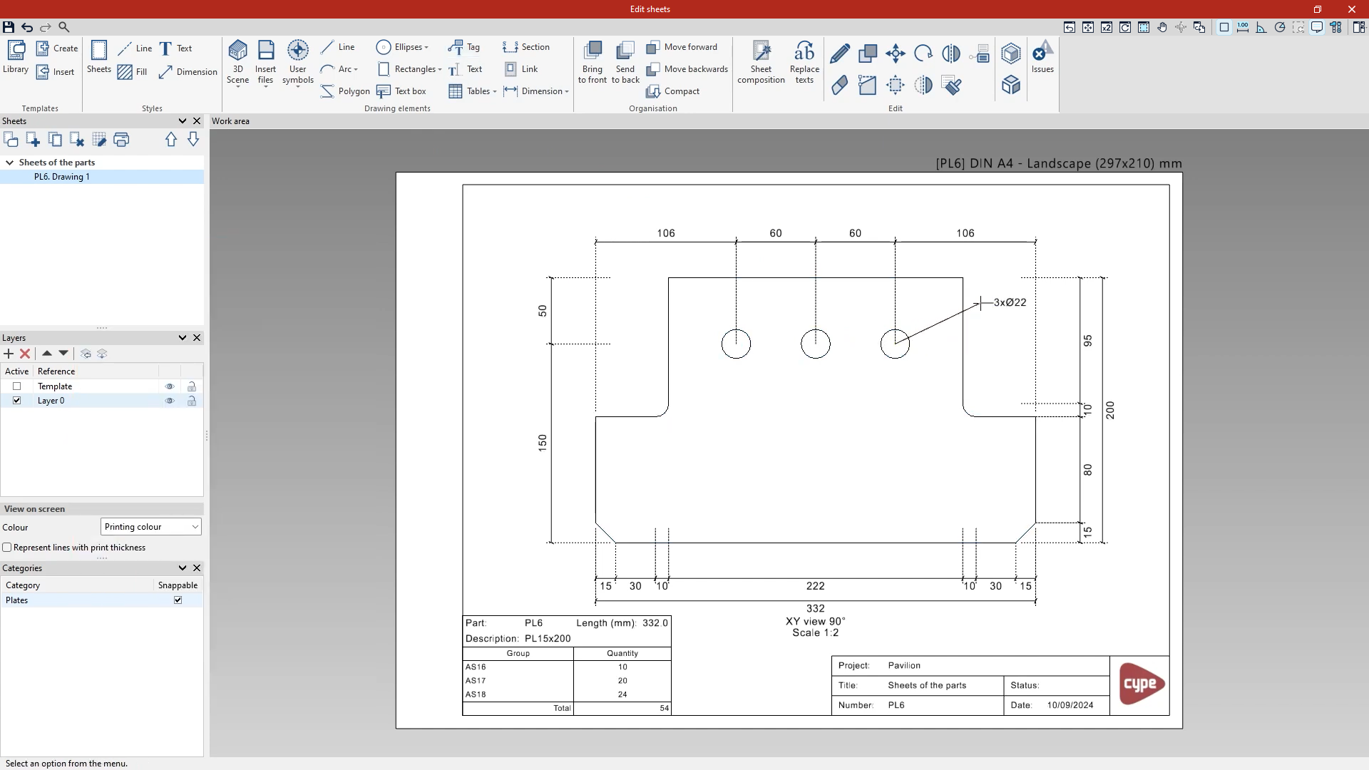
This sheet editing interface is shared across several CYPE programs and offers similar options:
- On the left-hand side, in the "Sheets" section, you can see that the program has generated a drawing with the part’s name, linked to the "Sheets of the parts" group if this has been specified in the "Generation options" in the "Documents" tab. If required, you can create and edit further sheets here to document the selected part.
- Next, in the "Layers" section, you can view the layer created to contain the "Template" – which may include the text box – as well as the active editing layer. If necessary, you can create and edit further layers, as well as manage their "View on screen".
- Further down, in the "Categories" section, you can specify whether each of the categories of elements displayed on the sheets is "Snappable" or not.
To add information to the selected sheet, use the tools in the top toolbar. Here you’ll find options for managing "Templates" and "Styles", adding "Drawing elements" to each sheet – such as "Lines" and "Text" – as well as "Organisation" and "Editing" tools.
Among the most useful are the following:
- In the "Drawing elements" pane, from the "3D scene" menu, you can "Insert" views manually or select "Insert predefined views" to have the program automatically generate a set of views of the selected part.
- If you choose this last option, the window that appears allows you to control the "Appearance", the "View titles" and their "Dimensions", select the "Views to be generated" and manage the "Sheets" into which they are inserted.
- You can also open the "Tables" menu to "Insert a predefined table". In this case, it is a "Table displaying the use of the part in the assemblies". The program can include this type of table in the sheet template.
- The "Tag" option, on the other hand, allows you to generate information automatically by selecting elements in the inserted views.
- The "Design" options include tools that allow you to select points on the elements in the view to measure their distance, area or the angle they form.
- In the "Edit" section, the options available include "Edit" to modify any of the graphic elements on the page, as well as "Move" to reposition them or "Delete".
Finally, in the "Sheets" section, the program offers an option to "Print" the desired sheets. In the window that appears when you click on this option, when you select the "Printer", you can choose to save a "PDF", "DXF" or "DWG" file, or print directly.
Once you have finished editing the sheets for the part, you can "Save" and close the window.
