

Sheet generation options
The sheet generation options can be configured by clicking on the "Generation options" button in the "Sheets" section of the top toolbar, within the "Documents" tab of the program’s main interface.

Generation options
The "Generation options" are organised into a dialog box with four tabs, which allow you to control the "Parts", "Assemblies", "Joints" and "Model views" sheets. Some of these options are common to all tabs, whilst others are specific to each tab.
"Parts" tab
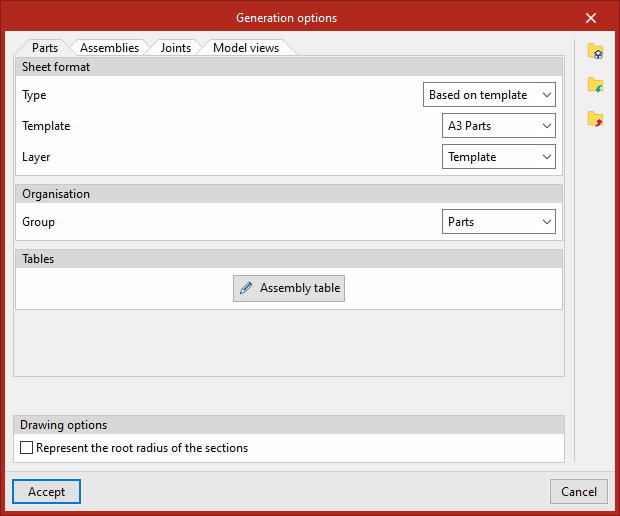
Firstly, under "Sheet format", select the format and template you wish to use to start new parts sheets. Under "Type", you can select "Empty", and then choose the sheet "Format" directly, or select "Based on template". In this case, you select a previously created library "Template" – which already has a specific sheet format associated with it – and the "Layer" onto which it will be loaded.
Further down, under "Organisation", select the sheet group to which the newly created part sheets will belong. By default, the "Part drawings", "Assembly drawings", "Joint drawings" and "Structure drawings" groups are available, but these can be modified by the user.
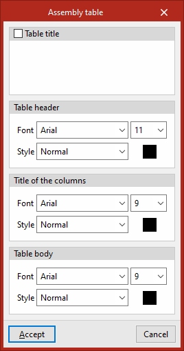
Next, in the "Tables" section, available under the "Parts" and "Assemblies" tabs, you can manage the "Font" and "Style" of the text in the predefined tables, including the "Table title" and "Table header", the "Column headings" and the "Table body".
At the bottom, under the "Drawing options" section, you can tick the box to "Represent the root radius of the sections". By default, this option is unticked.
"Assemblies" tab
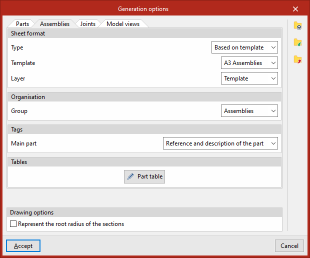
In the "Assemblies" tab, under "Sheet format", you can select the format and template you wish to use when creating new assembly sheets. Under "Type", you can select "Empty" and then choose the sheet "Format" directly, or select "From template". In this case, you select a previously created library "Template" – which already has a specific sheet format associated with it – and the "Layer" onto which it will be loaded.
Further down, under "Organisation", select the sheet group to which the newly created assembly sheets will belong. By default, the groups "Part drawings", "Assembly drawings", "Joint drawings" and "Structure drawings" are available, but these can be modified by the user.
In addition, there is a specific option here for editing the information that will appear in the automatic "Tags" in the main section of the assemblies. You can choose to display only the "Description", only the "Part number", or both the "Part number" and "Description" simultaneously.
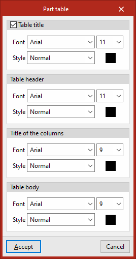
Next, in the "Tables" section, available under the "Parts" and "Assemblies" tabs, you can manage the "Font" and "Style" of the text in the predefined tables, including the "Table title" and "Table header", the "Title of the columns" and the "Table body".
At the bottom, under the "Drawing options" section, you can tick the box to "Represent the root radius of the sections". By default, this option is unticked.
"Joints" tab
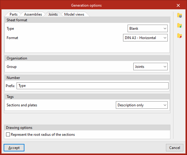
On the "Joints" tab, under "Sheet format", you can select the format and template you wish to use when creating new joint sheets. Under "Type", you can select "Empty", and then choose the sheet "Format" directly, or select "From template". In this case, you select a previously created library "Template" – which already has a specific sheet format associated with it – and the "Layer" onto which it will be loaded.
Further down, under "Organisation", select the sheet group to which the newly created joint sheets will belong. By default, the groups "Part drawings", "Assembly drawings", "Joint drawings" and "Structural drawings" are available, but these can be modified by the user.
There is also a specific field here where you can enter the "Prefix" that the program will use to "Number" the joints.
Furthermore, you can control the information that appears in the automatic "Tags" for "Sections and plates", specifying whether you want the "Reference and description" or "Description only" for these elements to be displayed.
At the bottom, under the "Drawing options" section, you can tick the box for "Represent the root radius of the sections". By default, this option is unticked.
"Model views" tab
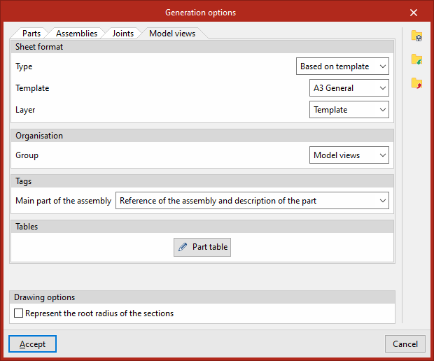
On the "Model views" tab, under "Sheet format", you can select the format and template you wish to use when creating new model view sheets. Under "Type", you can select "Empty" to then choose the sheet "Format" directly, or "From template". In this case, you select a previously created library "Template" – which already has a specific sheet format associated with it – and the "Layer" onto which it will be loaded.
Further down, under "Organisation", select the sheet group to which the new model view sheets will belong. By default, the groups "Part drawings", "Assembly drawings", "Joint drawings" and "Structural drawings" are available, but these can be modified by the user.
The information displayed in the "Tags" of the "Main part of the assembly" can also be configured. This may include:
- Only the "Description"
- The "Assembly reference"
- The "Reference to the whole and the part"
- The "Reference of the assembly and description of the part"
- Or the "Assembly reference and the part reference and description"
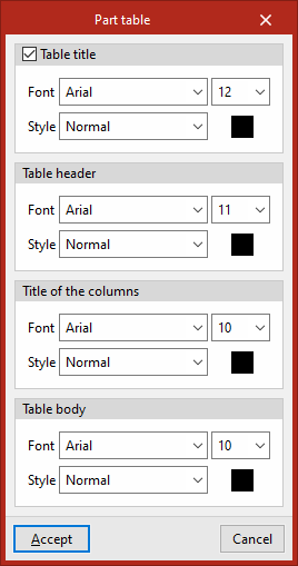
Next, in the "Tables" section, available under the "Parts" and "Assemblies" tabs, you can manage the "Font" and "Style" of the text in the predefined tables, including the "Table title" and "Table header", the "Column headings" and the "Table body".
At the bottom, under the "Drawing options" section, you can tick the box to "Represent the root radius of the sections". By default, this option is unticked.
Data export and import options
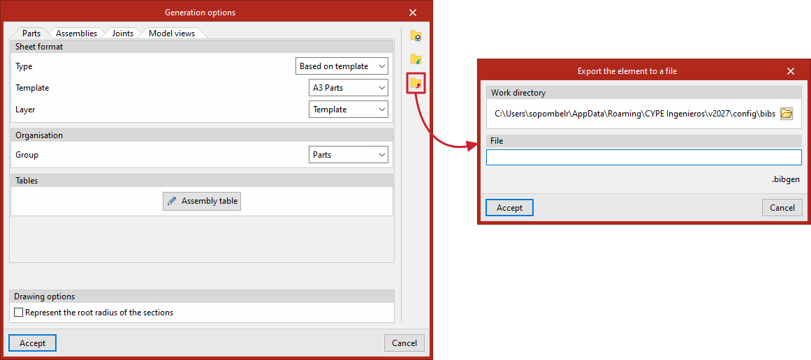
Finally, if you wish to save the settings for the sheet generation options to files on the hard drive, use the buttons on the right-hand side.
The "Export" option is used to save library information to a specific file. The libraries saved in a file can then be "Imported" into any project.
You can also carry out a "File selection with initial values for the creation of a new job". This way, when creating a new project, the program will automatically load the drawing generation options from the selected files.
Finally, to apply the changes, click "Accept".
