

"Model" tab interface
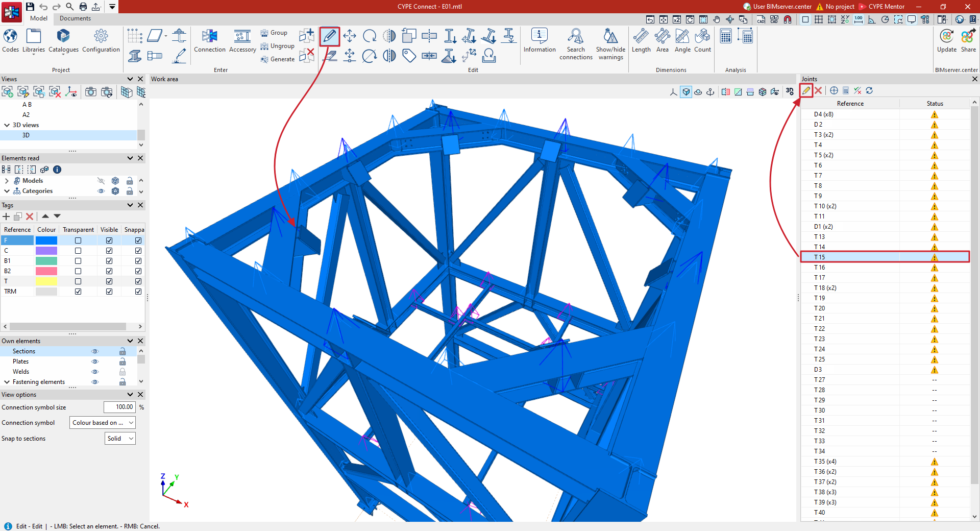
The CYPE Connect software’s user interface follows the same design principles as other CYPE tools. You have access to dockable and customisable windows, allowing you to tailor the workspace to the needs of your project.
At the top left of the screen, you will find two tabs:
- Model
- Documents
The "Template" tab is organised as follows:
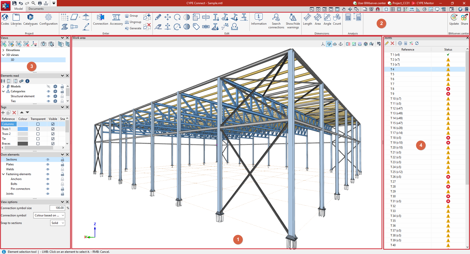
1. Work area (centre)
- Enter the project details.
- Change them.
- View them in 3D.
2. Main toolbar
- Change the general project settings (e.g. selecting the standard, managing element libraries).
- Insert the structural elements into the model (structural sections, plates, bolts, anchors, welds).
- Access the editing tools.
- Use the measurement tools on the model elements.
- Start the assembly group analysis.
- Link to and share the publication with a project on BIMserver.center.
3. Panels (left)
- Define the project views.
- Manage the visibility of read elements, tags and your own elements.
- Adjust the display settings.
4. List of assemblies (right)
- View the list of connections created in the model.
- For each connection, access its editing and analysis interface.
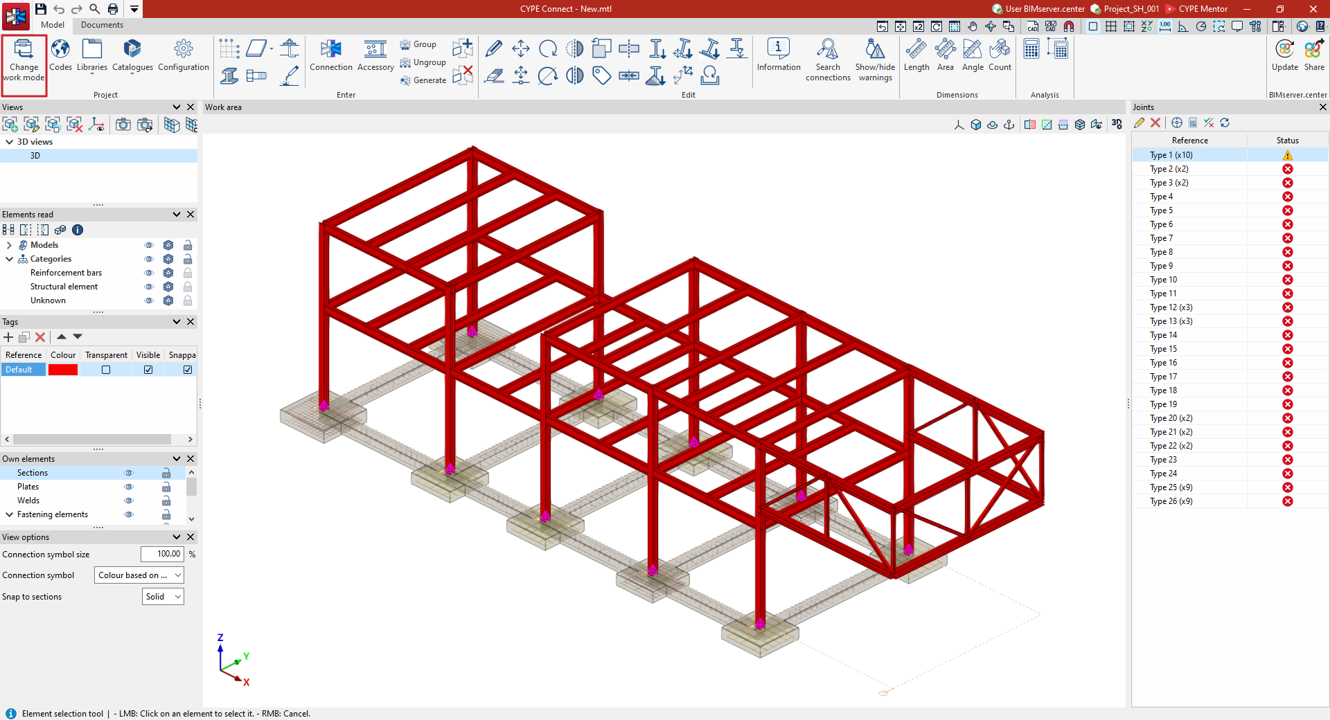
Changing the work mode
For jobs created in the "Project" work mode, the user has the option to "Change work mode" to "Fabrication". This option is available on the "Model" tab, within the "Project" section.
The program will then enable all options relating to the structure's fabrication, such as the ability to define the part and assembly numbering, and to edit and generate part drawings and assembly drawings (by activating the relevant options on the "Documents" tab), as well as exporting to manufacturing files in DSTV, STEP, IFC EM.11 or DXF for plates (by selecting the "Export" menu).
This change cannot be undone.
Configuring codes
To configure the design codes in the program, go to the "Model" tab and use the "Codes" option on the top toolbar.

This code is used by the program if the connections are defined using the connection editor, allowing them to be analysed using a finite element model and checks to be carried out on the elements within each connection.
Codes
After clicking on this option, you can select the standards for different materials from the various tabs in the pop-up window:
| Note: |
|---|
| The standards implemented in CYPE's programs can be viewed via the following link. |
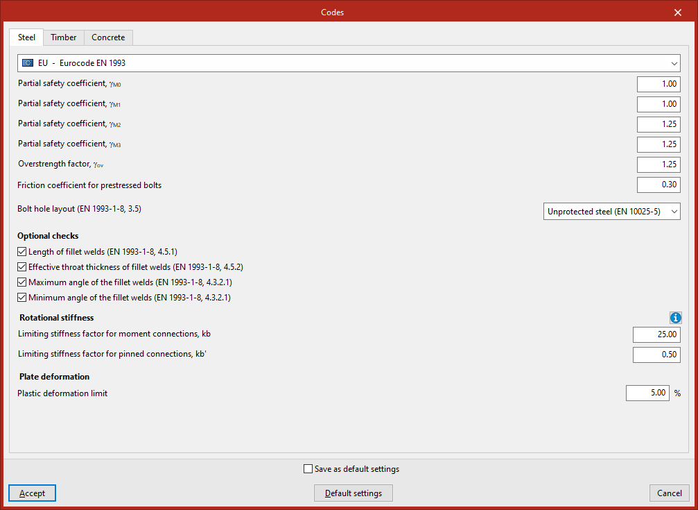
"Steel" tab
On this tab, you select the "Steel" standard from the drop-down menu.
When selecting a steel standard, you can customise its application by adjusting the values of various parameters associated with it at the bottom of the screen.
For example, if you select the EN 1993 Eurocode, you can review and/or modify the parameter values associated with this code, such as:
- The partial safety factors,
- The "Resistance reserve coefficient"
- The "Friction coefficient for prestressed bolts"
- In addition, the "Bolt hole layout (EN 1993-1-8, 3.5)" is selected.
Further on, various "Optional checks" relating to different sections of the codes can be enabled or disabled, such as the following:
- Length of fillet welds (EN 1993-1-8, 4.5.1)
- Effective throat thickness (EN 1993-1-8, 4.5.2)
- Maximum angle of the fillet welds (EN 1993-1-8, 4.3.2.1)
- Minimum angle of the fillet welds (EN 1993-1-8, 4.3.2.1)
The following factors can also be used to calculate the "Rotational stiffness":
- Limiting stiffness factor for moment connections, kb
- Limiting stiffness factor for pinned connections, kb
Finally, for the "Plastic strain", you can enter the "Plastic deformation limit" (%).
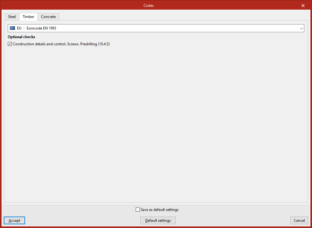
"Timber" tab
On this tab, you can select the "Timber" standard from the drop-down menu.
When you select a timber standard, you can configure its application at the bottom of the page.
For example, if the EN 1995 Eurocode is selected, various "Optional checks" relating to different sections of the standard can be enabled or disabled, such as the following:
- Construction details and control. Screws. Predrilling (10.4.5)
"Concrete" tab
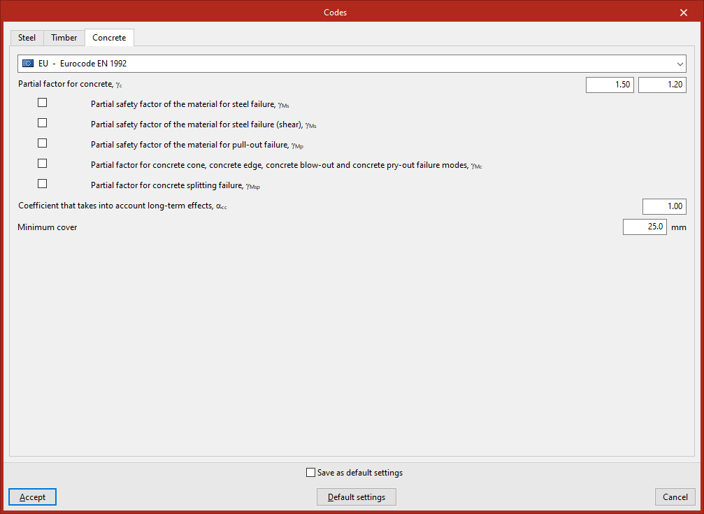
On this tab, you select the "Concrete" standard from the drop-down menu.
Once you have selected the concrete standard, you can configure how it is applied at the bottom of the screen.
For example, if EN 1992 Eurocode is selected:
- The boxes corresponding to the various partial safety factors are ticked or unticked, and their values are checked for steady-state, transient and accidental conditions.
- The "Coefficient that takes into account long-term effects" is entered.
- Furthermore, the "Minimum cover" for the reinforcement is specified.
To confirm the changes, click "Accept".
Element and material libraries
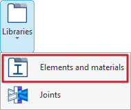
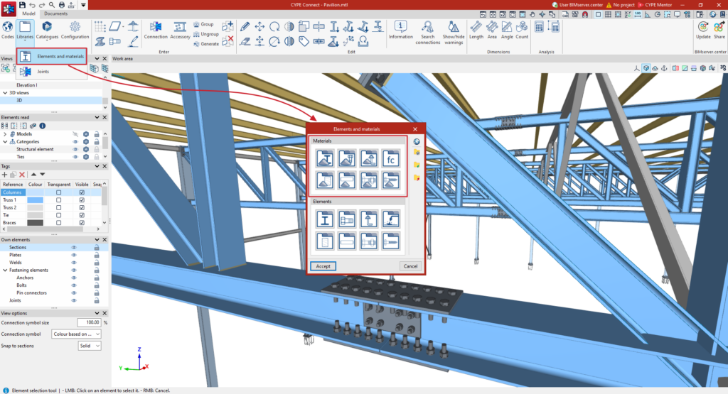
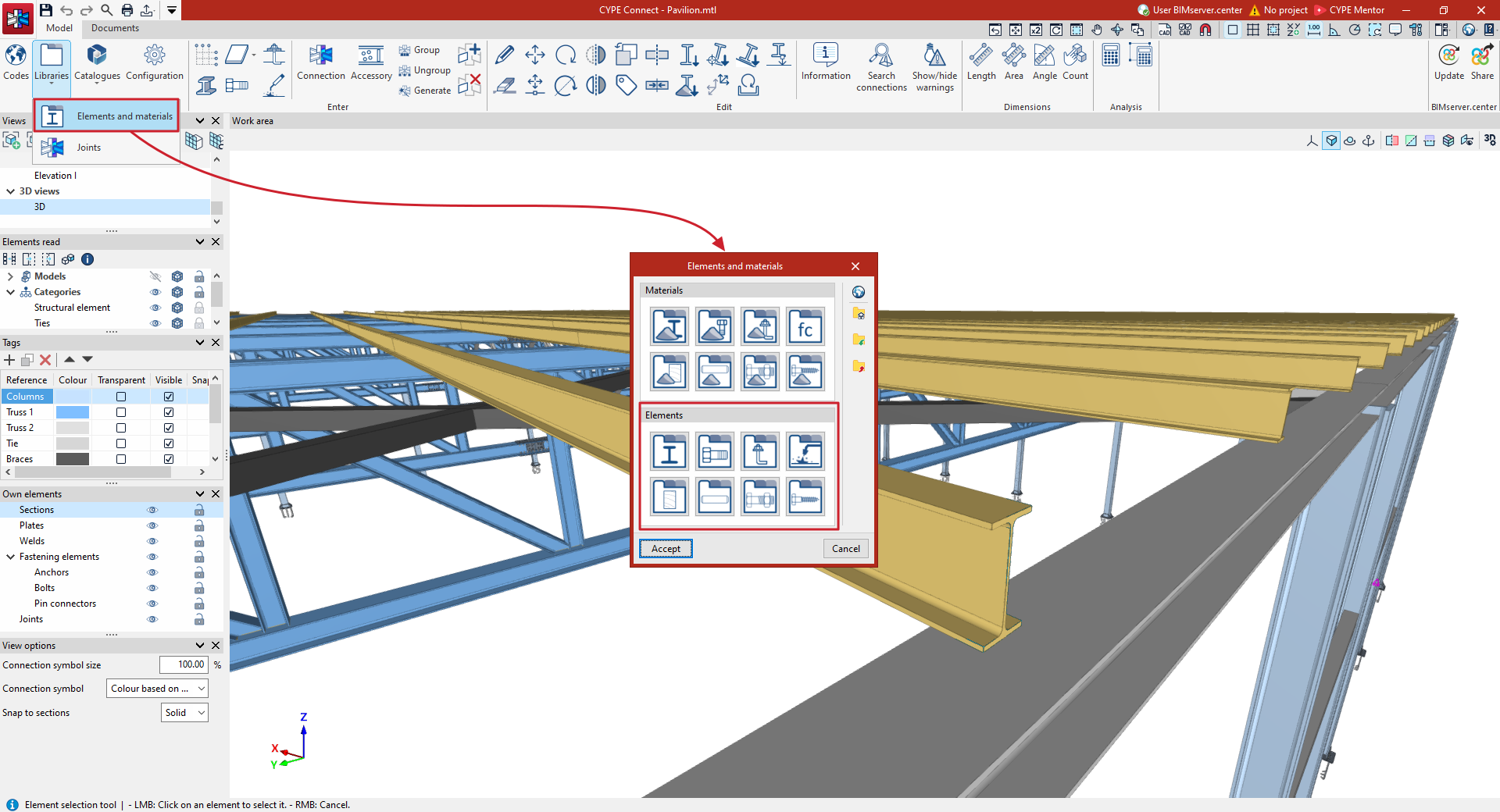
To configure the material and element libraries, from the "Model" tab on the program's main interface, open the "Libraries" menu on the top toolbar, which is available within the "Project" section.

Next, select "Elements and materials".
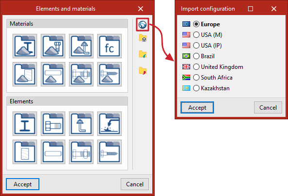
In the window that appears, you can access the various "Materials" and "Elements" libraries for the structure using the various buttons provided.
Importing settings by country or region
In addition, the program offers the "Import settings" option on the right to import predefined libraries of materials and elements from a specific country or region after selecting it from the list:
- Europe
- USA (M)
- USA (IP)
- Brazil
- United Kingdom
- South Africa
- Kazakhstan
When you click "Accept", the libraries for all materials and elements are generated automatically, replacing the data previously entered.
Importing and exporting libraries
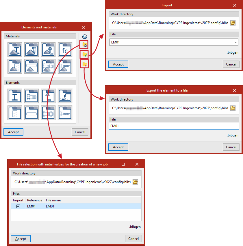
On the right-hand side, there is a set of additional tools for importing and exporting the material and element libraries that have been configured in the project.
The "Export" option is used to save library information to a specific file. The libraries saved to a file can then be "Imported" into any project.
You can also carry out a "File selection with initial values for the creation of a new job". This means that, when creating a new project, the program automatically loads the materials and elements saved in the selected files, so that the libraries do not appear empty.
Materials libraries
The "Materials" libraries can be found in the section of the same name, within the window that appears when you click on the "Elements and materials" option in the "Libraries" menu.
From here, you can click on the following options to configure:
- Types of steel for sections and plates
- Types of steel for bolts
- Types of steel for anchors
- Types of concrete
- Types of timber
- Materials for dowels
- Materials for bolts
- Materials for screws
Once the library materials have been defined in each specific editing panel, click "Accept" to return to the previous window.
After clicking "Accept" again, the library materials will be available for use when defining structural bars and connections. The first element in each list will be taken as the default value.
| Note: |
|---|
| If the adopted workflow includes importing from a BIM model of the structure developed in CYPECAD or CYPE 3D, CYPE Connect will import the necessary element types and automatically add them to the project library, provided they are compatible with the program. |
Types of steel for sections and plates
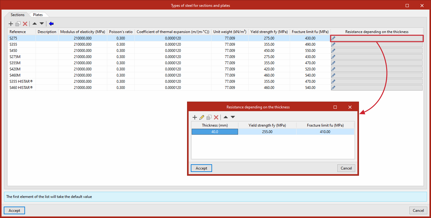
To edit the "Types of steel for sections and plates", click the option to open a window where you can enter the materials manually.
At the top, the program provides options to "Add", "Copy", "Delete" or move items in the list.
In each row of the table, the following are entered:
- Reference
- Description
- Modulus of elasticity
- Poisson’s ratio
- Coefficient of thermal expansion
- Unit weight
- Yield strength
- Fracture limit
- In addition, on the right-hand side, you can specify the "Resistance depending on the thickness".
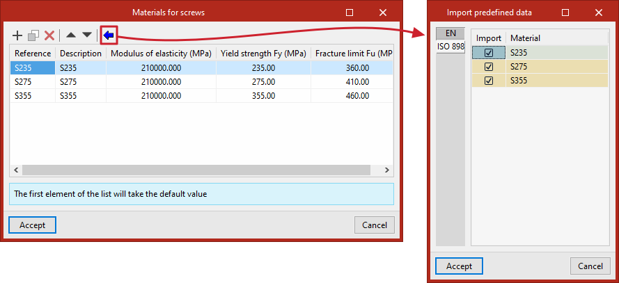
You can also "Import predefined data" by clicking on the relevant option at the top. Then, tick the relevant boxes to "Import" the required materials and click "Accept".
Types of steel for bolts
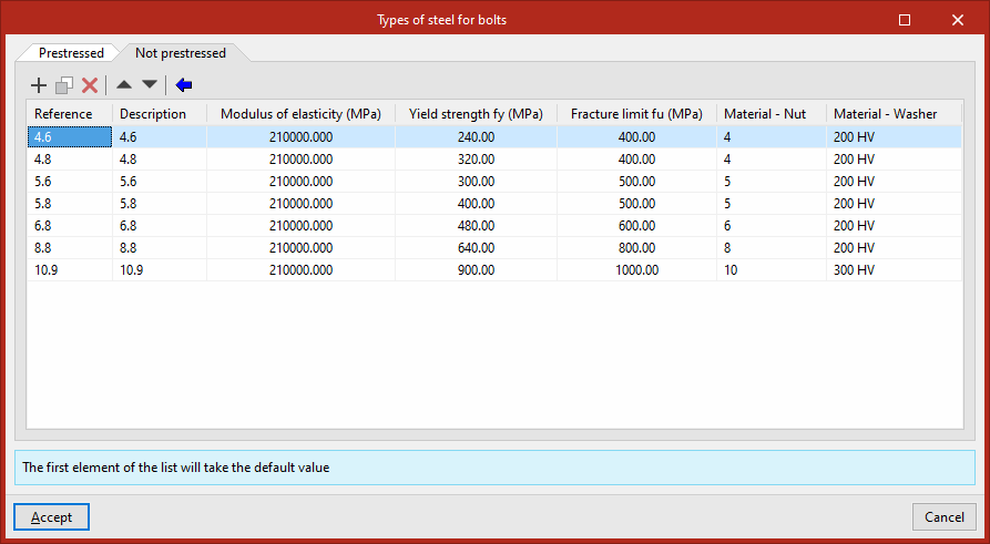
The program allows you to specify the steel grades for prestressed and non-prestressed bolts in the two available tabs ("Prestressed", "Non-prestressed").
In each row of the table, the following properties of the steel used for screws are entered:
- Reference
- Description
- Modulus of elasticity
- Yield strength
- Fracture limit
- Material – Nut
- Material – Washer
You can enter this data manually or "Import predefined data" from different standards using the relevant option.
Types of steel for anchors
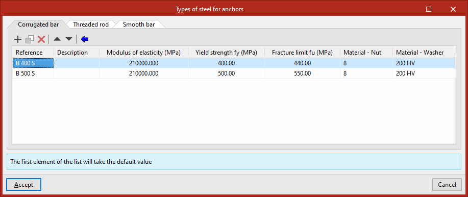
You can define the steel types for "Corrugated bar", "Threaded rod" and/or "Smooth bar" anchors in the relevant tabs.
In each row of the table, the following properties of the steel used for anchors are entered:
- Reference
- Description
- Modulus of elasticity
- Yield strength
- Fracture limit
- Material – Nut
- Material – Washer
You can enter this data manually or "Import predefined data" from different standards using the relevant option.
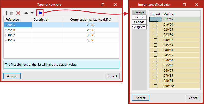
Types of concrete
To define the types of concrete available on site, the following properties are entered in each row of the table:
- Reference
- Description
- Compressive strength
You can enter this data manually or "Import predefined data" using the relevant option.
Types of timber
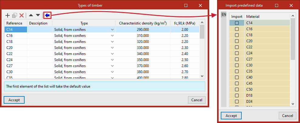
To define the types of timber available on site, the following properties are entered in each row of the table:
- Reference
- Description
- the "Type", which can be:
- Solid, from conifers
- Solid, derived from broad-leaved species
- Glued laminated, homogenous
- Glued laminated, combined
- Characteristic density
- and the "fc,90,k" value.
You can enter this data manually or "Import predefined data" using the relevant option.
Materials for dowels
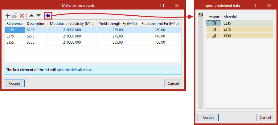
To define the materials available on site for dowels, the following properties are entered in each row of the table:
- Reference
- Description
- Modulus of elasticity
- Yield strength
- Fracture limit
You can enter this data manually or "Import predefined data" using the relevant option.
Materials for bolts
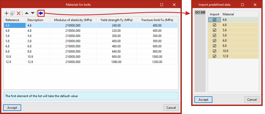
To define the bolt materials available on site, the following properties are entered in each row of the table:
- Reference
- Description
- Modulus of elasticity
- Yield strength
- Fracture limit
You can enter this data manually or "Import predefined data" using the relevant option.
Materials for screws
To define the materials for screws available on site, the following properties are entered in each row of the table:
- Reference
- Description
- Modulus of elasticity
- Yield strength
- Fracture limit
You can enter this data manually or "Import predefined data" using the relevant option.
Element libraries
The "Elements" libraries can be found in the section of the same name, within the window that appears when you click on the "Elements and materials" option in the "Libraries" menu.
From here, the following options can be selected to define:
- Section library
- Bolt library
- Pre-installed anchor library
- Electrode library
- Timber sections library
- Dowel library
- Bolt library
- Screw library
Once the library elements have been defined in each specific editing panel, click "Accept" to return to the previous window.
After clicking "Accept" again, the library elements will be available for use in defining the structure and joins. The first element in each list will be taken as the default value.
| Note: |
|---|
| If the adopted workflow includes the process of importing from a BIM model of the structure developed in CYPECAD or CYPE 3D, CYPE Connect will import the necessary element types and add them to the project library automatically, provided they are compatible with the program. |
Section library
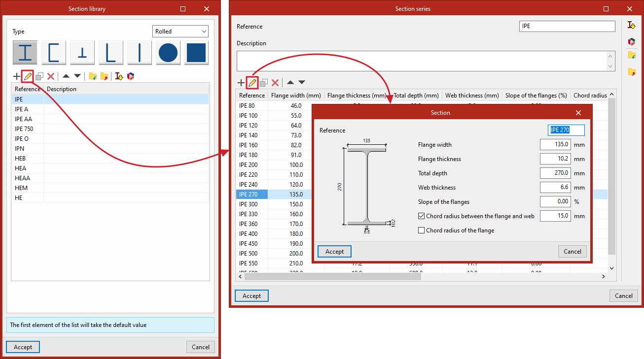
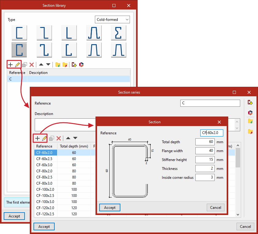
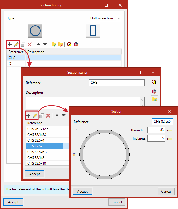
To edit the "Section library", click on the option to open a window displaying the range of steel sections.
First, you select the section "Type", which can be:
- Laminated
- Reinforced
- Rolled
- Hollow section
For each section type, the program offers various options, which can be viewed via this link. For example, selecting Rolled takes you to the following section tables:
- I sections
- U sections
- T sections
- Angles
- Flat bars
- Solid round bars
- Solid square bars
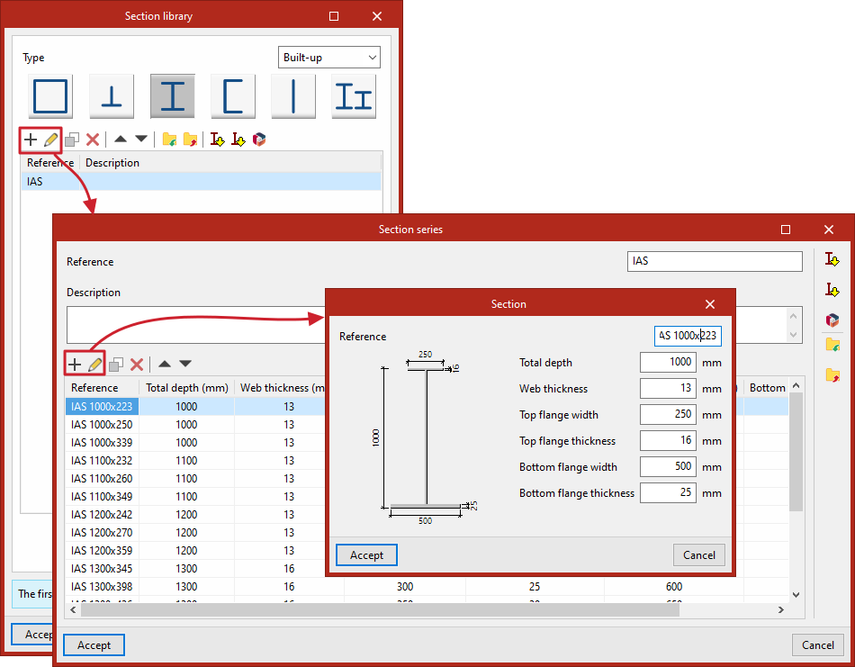
At the top of the table, the program provides options to "Add", "Edit", "Copy", "Delete" or move elements in the list.
You can also "Import" and "Export" the information for the selected elements to a file on the hard drive.
The option on the far right allows you to "Import predefined section series" taken from various manufacturers’ technical data sheets and standards.
You can also import "Manufacturer catalogues" included in the Open BIM Database using the following option at the top of the page.
Each row in the table corresponds to a specific set of sections, which has a "Reference" and a "Description".
You can view or edit the data by selecting a series and clicking on "Edit".
This opens the "Section series" window. All the sections defined in the selected series are displayed here.
Once again, you can "Add", "Edit", "Copy", "Delete" or move profiles in the list using the tools at the top, as well as "Import predefined profile sets" or "Manufacturer catalogues" "Import" and "Export" the information for the selected series to a file on the hard drive, using the options in the right-hand column.
When you "Add" or "Edit" a section in the table, the "Section" window opens. Here you can enter its "Reference" number, as well as the geometric parameters that define it.
For example, in a double-T section, these are as follows:
- Flange width
- Flange thickness
- Total depth
- Thickness of the web
- Slope of the flanges
- Chord radius between the flange and web
- Chord radius of the flange
To confirm the values entered, click on "Accept".
Bolt library
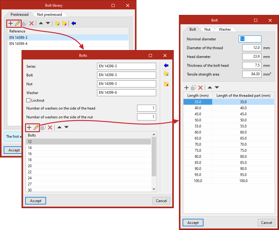
In this library, different bolt series are entered into different lists, one for each bolt type ("Prestressed" and "Not prestressed"). At the top, the program provides tools to In this library, different bolt series are entered into different lists, one for each bolt type ("Prestressed" and "Not prestressed"). At the top, the program provides tools to "Add", "Copy", "Delete" or move items within each list.
"Add", "Copy", "Delete" or move items within each list.
You can also "Import predefined data" by clicking on the relevant option at the top. Then, tick the relevant boxes to "Import" the desired items and click "Accept".
Each series of bolts is defined by the part numbers for the "Series", the "Bolt", the "Nut" and the "Washer"; furthermore, you indicate whether or not a "Lock nut" is required by ticking the relevant box, enter the "Number of washers on the side of the head" and the "Number of washers on the side of the nut", and provide the list of available "Bolts".
The following are defined in the edit panel for each bolt in this list:
- On the "Bolt" tab:
- Nominal diameter
- Diameter of the thread
- Head diameter
- Thickness of the bolt head
- Tensile strength area
- In the "Nut" tab:
- Outside diameter
- Inside diameter
- Thickness
- In the "Washer" tab:
- Outside diameter
- Inside diameter
- Thickness
- Finally, the list of available lengths is shown at the bottom, including the total "Length" of the screw and the "Length of the threaded section".
Library of pre-installed anchors
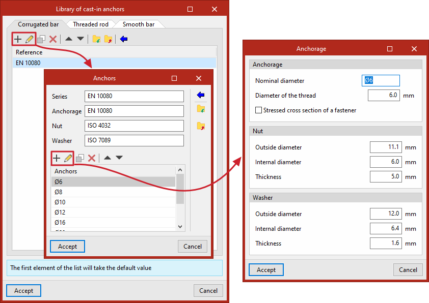
In this library, various series of pre-installed anchors are included in different lists, one for each type of anchor ("Corrugated bar" "Threaded rod" and "Smooth bar"). At the top, the program provides tools to "Add", "Copy", "Delete" or move items within each list.
You can also "Import predefined data" by clicking on the relevant option at the top. Then, tick the relevant boxes to "Import" the desired items and click "Accept".
Each series of anchors is defined by the part numbers for the "Series", the "Anchor", the "Nut" and the "Washer", and by the list of available "Anchors".
The following are defined in the edit panel for each anchor in this list:
- "Anchorage" data:
- Nominal diameter
- Shaft diameter
- Effective cross-sectional area of the anchor (optional)
- "Nut" data:
- Outside diameter
- Inside diameter
- Thickness
- "Washer" data:
- Outside diameter
- Inside diameter
- Thickness
Electrode library
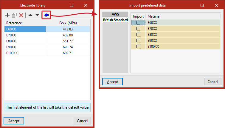
In this library, various electrodes are added to a list. At the top, the program provides functions to "Add", "Copy", "Delete" or move elements in the list.
You can also "Import predefined section series" by clicking on the relevant option at the top. Then, tick the relevant boxes to "Import" the desired elements and click "Accept".
Each electrode is defined by:
- Reference
- Strength (Fexx)
Timber section library
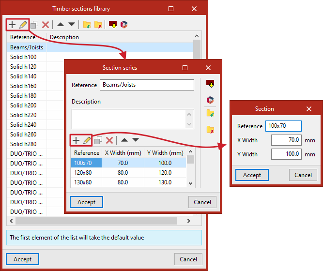
In the timber section library, different section series are added to a list. At the top, the program provides tools to "Add", "Copy", "Delete" or move elements in the list.
You can also "Import predefined section series" by clicking on the relevant option at the top. Then, tick the relevant boxes to "Import" the desired elements and click "Accept".
In addition, it is possible to import "Manufacturer catalogues" included in the Open BIM Database using the following option at the top of the page.
Each "Section series" is defined by its "Reference", its "Description" and the list of available sections.
In each section of the list, the following is entered:
- Reference
- X width
- Y width
Pin library
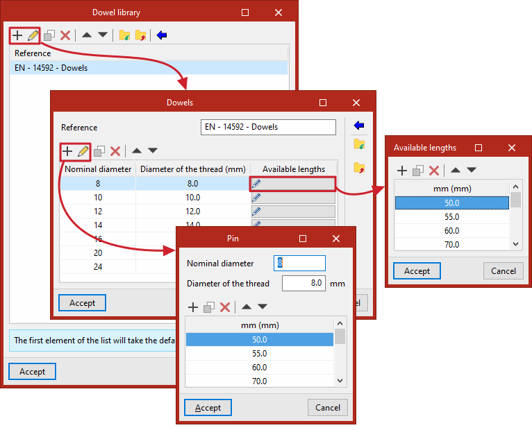
In the pin library, different sets of pins are added to a list. At the top, the program provides tools to "Add", "Copy", "Delete" or move elements in the list.
You can also "Import predefined data" by clicking on the relevant option at the top. Then, tick the relevant boxes to "Import" the desired elements and click "Accept".
Each series of "Pins" is defined by its "Reference" and the list of available pins.
For each element in the list, the following details are entered in its edit panel:
- Nominal diameter
- Shaft diameter
- Available lengths
Bolt library
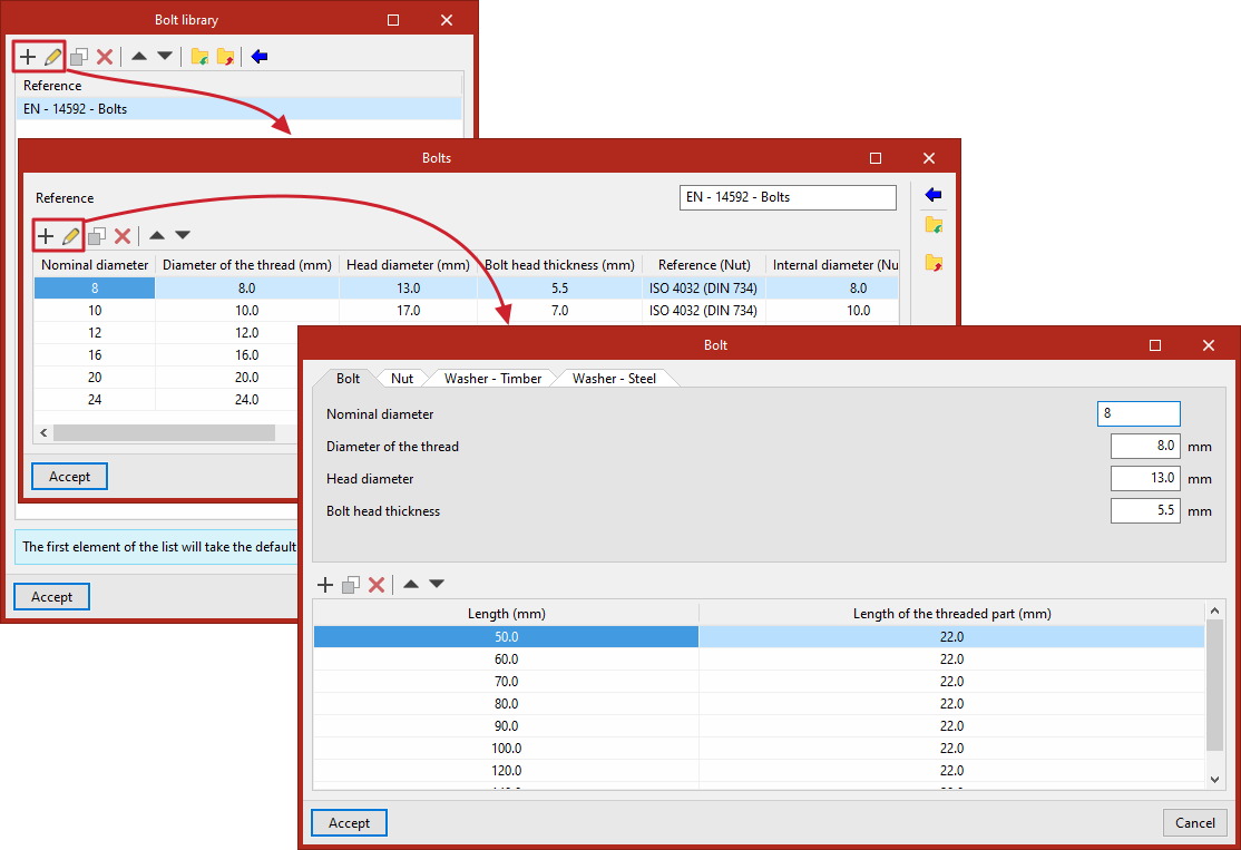
In the bolt library, different bolt series are entered into a list. At the top, the program provides tools to "Add", "Copy", "Delete" or move items in the list.
You can also "Import predefined data" by clicking on the relevant option at the top. Then, tick the relevant boxes to "Import" the desired items and click "Accept".
Each "Bolt" series is defined by its "Part number" and the list of available bolts.
For each element in the list, enter the following details in its edit panel:
- The "Bolt" tab includes:
- Nominal diameter
- Shaft diameter
- Head diameter
- Bolt head thickness
- The "Nut" tab includes:
- Reference
- Inside diameter
- Outside diameter
- Thickness
- Lock nut (by ticking the relevant box)
- The "Washer – Timber" and "Washer – Steel" tabs show the specifications for washers made from both materials:
- Reference
- Outside diameter
- Thickness
- Finally, the list of available lengths is shown at the bottom, including the total "Length" of the bolt and the "Length of the threaded part".
Bolt library
In the bolt library, different bolt series are added to a list. At the top, the program provides functions to "Add", "Copy", "Delete" or move elements in the list.
You can also "Import predefined data" by clicking on the relevant option at the top. Then, tick the relevant boxes to "Import" the desired items and click "Accept".
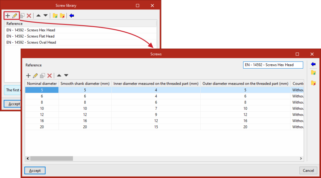
For each series of "Screws", the "Reference" and the list of available screws are specified.
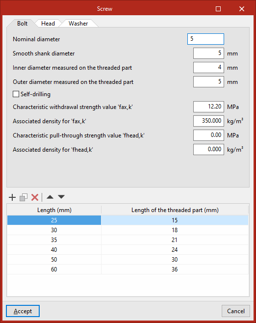
For each lag screw on the list, enter the following details in its edit panel:
- The "Bolt" tab includes:
- Nominal diameter
- Smooth shank diameter
- Inner diameter of the threaded part
- Outer diameter of the threaded section
- Self-drilling (select the checkbox as applicable)
- Characteristic withdrawal strength value 'fax,k'
- Associated density for 'fax,k'
- Characteristic pull-through strength value 'fhead,k'
- Associated density for 'fhead,k'
- The "Head" tab includes:
- Countersunk part of the head (Non-countersunk, Countersunk or Straight), and its properties:
- Diameter of the external part of the head
- Thickness of the external part of the head
- External part of the head (Without external part, Cylindrical, Square or Hemispherical), and its properties:
- Diameter of the external part of the head
- Thickness of the external part of the head
- Countersunk part of the head (Non-countersunk, Countersunk or Straight), and its properties:
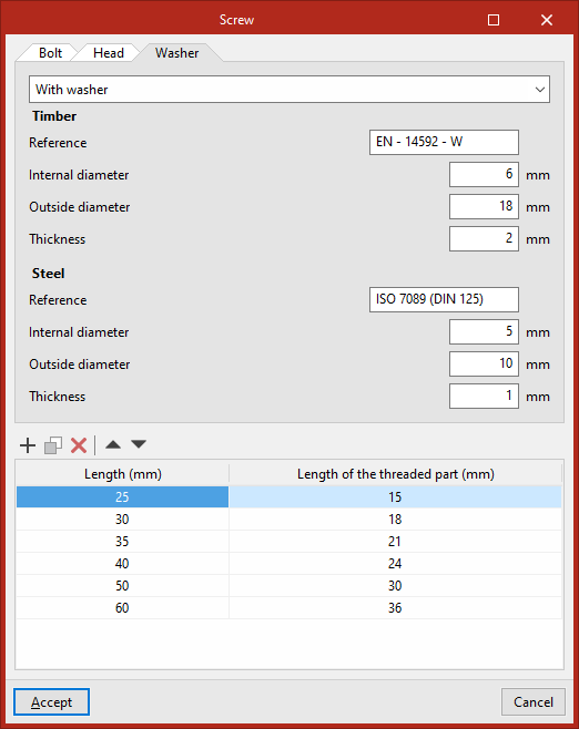
- On the "Washer" tab, select one of the following options:
- Without washer
- With washer, in which case the definition applies to both "Timber" and "Steel":
- Reference
- Inside diameter
- Outside diameter
- Thickness
- With built-in washer, including:
- External diameter of the built-in washer
- Thickness of the built-in washer
- Finally, the list of available lengths is shown at the bottom, including the total "Length" of the screw and the "Length of the threaded part".

Joint libraries
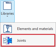
To view the user's joint library, from the "Model" tab on the program's main interface, open the "Libraries" menu on the top toolbar, which is located within the "Project" section.
Next, select "Joints".
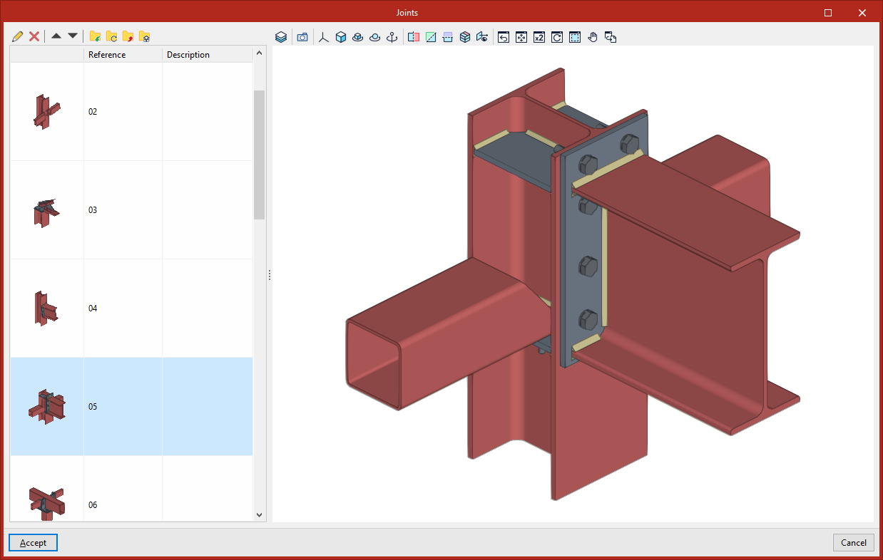
The window that appears displays a list of the joints created by the user and saved in the project currently open in the program.
The following is shown for each connection:
- Thumbnail view of the joint
- Reference
- Description
On the right is a 3D view in which you can move, zoom and rotate the joint selected from the list.
At the top of the list, you will find the options for managing this user joint library.
- Edit
Modify the details of the selected joint. - Delete
Remove the selected joint from the library. - Import the elements saved in the drive to the project
Import the joints contained in the selected .bibgen file into the project library. - Update the elements used in the project
Update the information for the selected joints based on the information contained in the associated .bibgen files. - Export the item to a file
Export the selected references to a .bibgen file on the hard drive. - Selecting a file with initial values for creating a new
project
Select a .bibgen file from your hard drive. The information contained in this file will be used to automatically create the user's joint library when creating a new project.
| Note: |
|---|
| The information displayed in this window is similar to that shown via the "User joints" option within the edit panel for each joint. The user joint library can be populated by exporting the data for a specific joint from that joint's edit window (using the "Export" option within the "Library" section of the "Model" tab). Joints from the user joint library can be used when defining joints (using the "Import" or "Auto" option within the "Library" section of the "Model" tab in each joint's editing panel, or via the "Generate" option in the "Enter" section of the "Model" tab on the program's main interface). |
Importing and managing manufacturers' catalogues
In the "Project" section of the main toolbar on the "Model" tab, you will find the options for managing manufacturers' product catalogues so that they can be incorporated into the project:

Catalogues
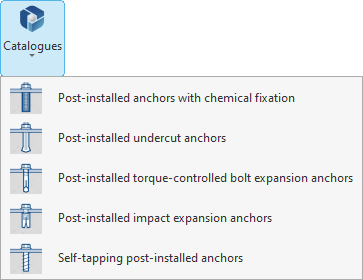
Clicking on the "Catalogues" option opens a menu showing the different types of items into which you can import and use manufacturer products:
- Post-installed anchors with chemical fixation
- Post-installed undercut anchors
- Post-installed torque-controlled bolt expansion anchors
- Post-installed impact expansion anchors
- Self-tapping post-installed anchors
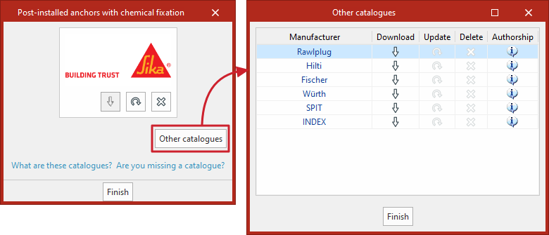
When you select one of these options, a window opens where you can download the various manufacturer catalogues available for the selected element type via the connection to the Open BIM Database, making it easier to enter data into the program for project development.
The following options are displayed for each manufacturer:
- Download
Download the manufacturer’s catalogue. The products in the catalogue will be available in the project. - Update
Update the catalogue for the selected manufacturer to the latest version, deleting the version previously downloaded to the project. - Delete
Delete the catalogue for the selected manufacturer. The products in the catalogue will no longer be available in the project.
You can also click on the "Other catalogues" option to download and update catalogues from other manufacturers.
If a user requires a catalogue that is not included in the program, they can request it via the "Are you missing a catalogue?" link.
| Note: |
|---|
| Products from the downloaded catalogues can be selected by inserting the element of the selected type (for example, anchors) into the model or connection. |
Project configuration options
The program offers the following configuration options in the "Project" section of the top toolbar, on the "Model" tab:

Settings
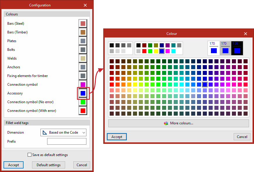
Clicking on this option opens the "Settings" window, where you can adjust the following settings.
Firstly, in the "Colours" section, you can edit the colours of the following elements of the model’s structure and symbols according to your preferences:
- Bars (Steel)
- Bars (Timber)
- Plates
- Bolts
- Welds
- Anchors
- Fixing elements for timber
- Connection symbol
- Accessory
- Connection symbol (No error)
- Connection symbol (With error)
You can then adjust the "Fillet weld tags":
- "Dimension" may refer to the "Standard", "Throat" or "Leg", depending on the selection made from the drop-down menu;
- In addition, you can enter the "Prefix" for your reference.
Entering grids
Grids are sets of reference lines that facilitate the geometric modelling of the structure. To insert grids, select the "Model" tab and click on the "Grid" option in the "Enter" section of the top toolbar.

Grid
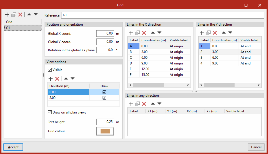
Clicking on this option opens the "Grid" window. Here, in the table on the left-hand side, you can "Add", "Copy", "Delete" and reorder the grids for the project.
First, click on "Add" to create a new grid:
- Next, on the right, enter the "Reference".
- Under "Position and orientation", you can define the parameters of the grid’s origin to position it in space by entering its "Global X coordinate", its "Global Y coordinate" and the "Rotation in the global XY plane".
- Further down, under "View options", tick the "Visible" box to enable the grid to be visible in all views. You can also set the visibility of the grid lines at different heights. To do this, add rows to the table to create different "Dimensions" and tick the "Draw" box for each one. If desired, you can "Draw on all plan views" by ticking the corresponding box.
- At the bottom, you can set the "Text height" and the "Grid colour".
- In the two boxes at the top right, you can add the "Lines in the X-directions" and "Lines in the Y-directions" for the grids. Here, you can add lines to each table and set their "Coordinates", enter their "Labels" and define their visibility – whether to make them visible "At the origin", "At the end", "At both ends" or "Not" visible.
- Finally, using the table at the bottom, you can draw "Lines in any direction". To do this, enter the coordinates of the start and end points that define each line in the "X1", "Y1", "X2" and "Y2" columns.
Once you have finished defining the grid, click "Accept" to close the window. The grid will now be visible in the various views of the model, depending on the settings used.
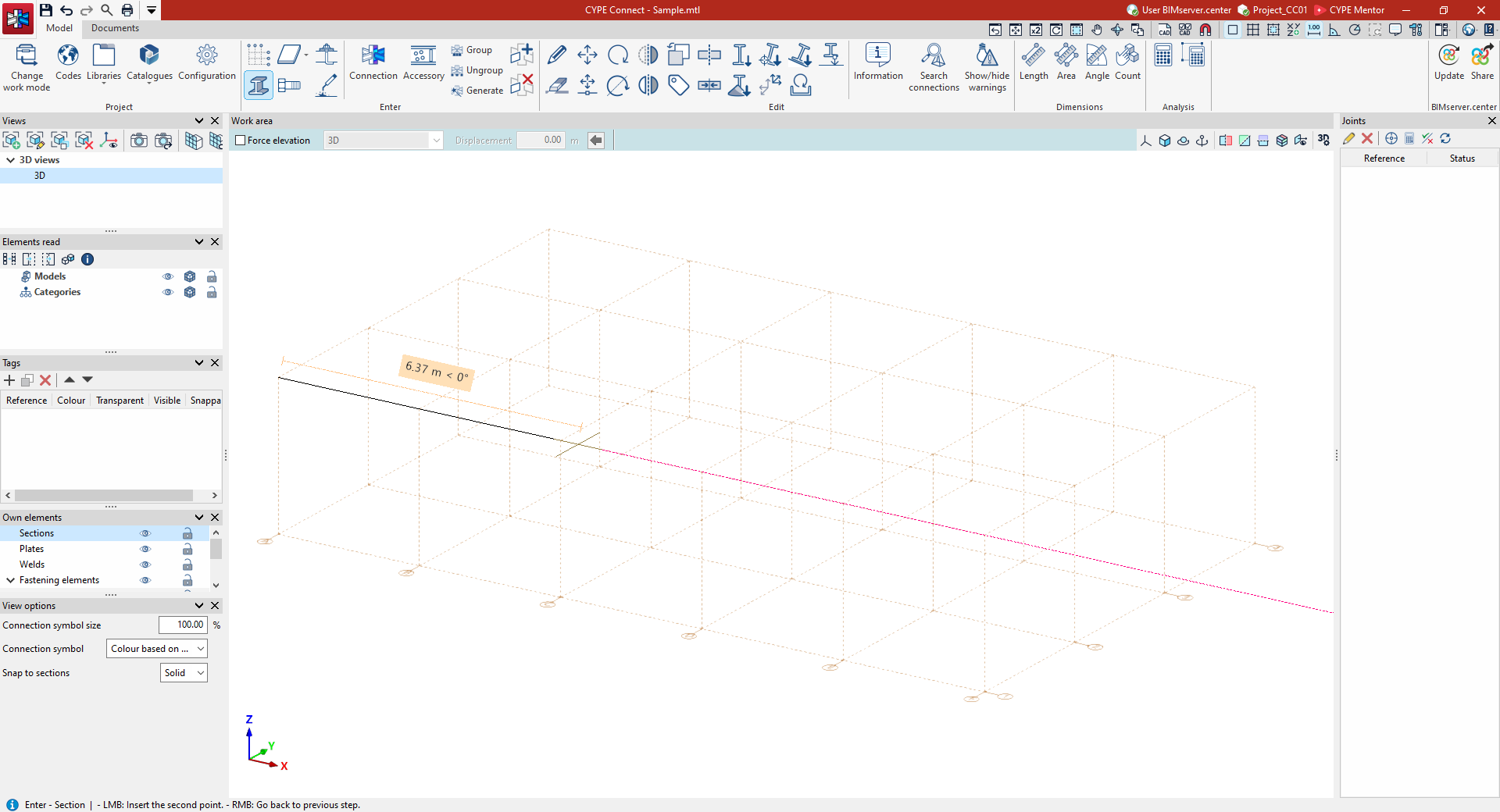
Grids can be used during the modelling phase to draw any element, as they are snappable. They are particularly useful for positioning the bars of a modular structure or for projects that are developed directly within the program without first importing data.
Entering sections
Sections can be entered directly. To do this, in the "Model" tab of the program’s main interface, select the "Section" option from the "Enter" section on the top toolbar.

Section
Defining section properties
In the window that appears when you click on the "Section" option, you can define the "Properties of the new section". First, select the "Type" from those available in the first drop-down menu:
- Hot-rolled section
- Built-up section with rolled steel plates
- Cold-formed section
- Hollow section
- Timber section
Next, in the drop-down menu, you can select the specific section type. For example, if you are using a "Rolled" section, the program allows you to choose from an I section, a U section, an angle section, a generic plate, a T section, a square bar or a round bar.
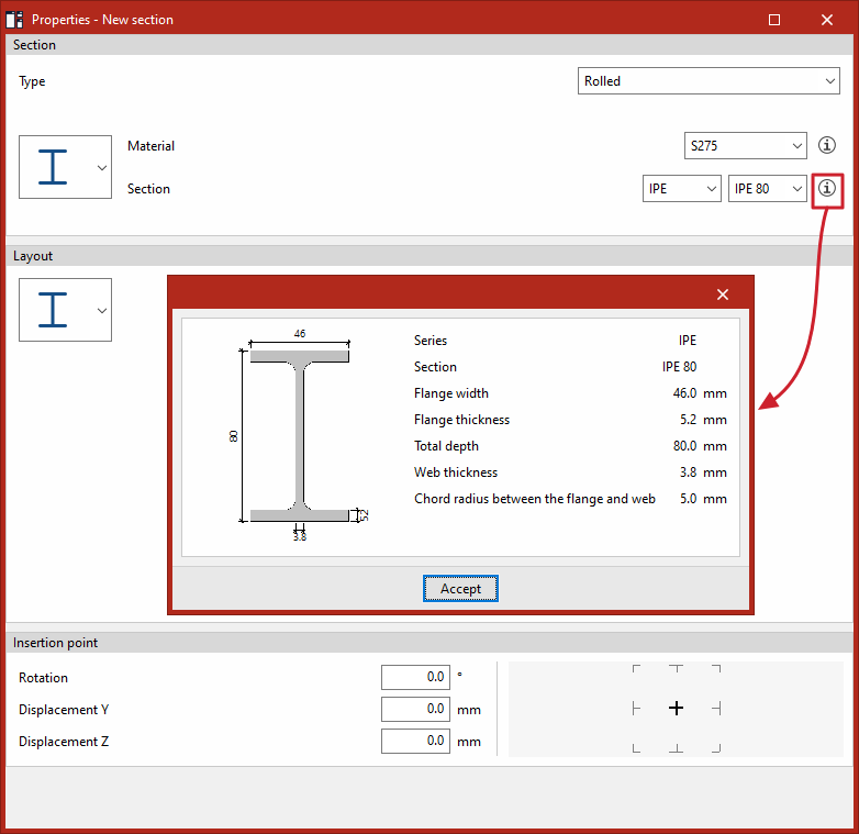
You can select the "Material" from the drop-down menu from those available in the library. Alternatively, if you click on the information button on the right now, you can view its "Reference", "Description" and material properties.
Next, the "Section" is defined by selecting a "Section series" directly from the available library, then a specific "Section" from that series using the drop-down menus. Similarly, if required, click the information button on the right to view its geometric properties, such as the section dimensions in the series, the thickness, or the root radius.
Next, in the drop-down menu under the "Layout" section, the section layout is specified (for example, for a double-T section, you can choose whether it is a simple section, with lateral plates, double welded-in box, or double or simple with haunches). Each of these options offers different configuration possibilities.
Finally, under "Insertion point", you can specify the "Rotation", "Y Displacement" and "Z Displacement" of the section along its local axes. On the right-hand side, you can specify the alignment point, either on the section’s axis, at the centre of one of its faces, or at one of its corners.
| Note: |
|---|
| The available sections and layouts can be viewed via this link. |
Adding a section to the work area
Once you have defined its properties, you must enter the section's geometry into the "Work area".
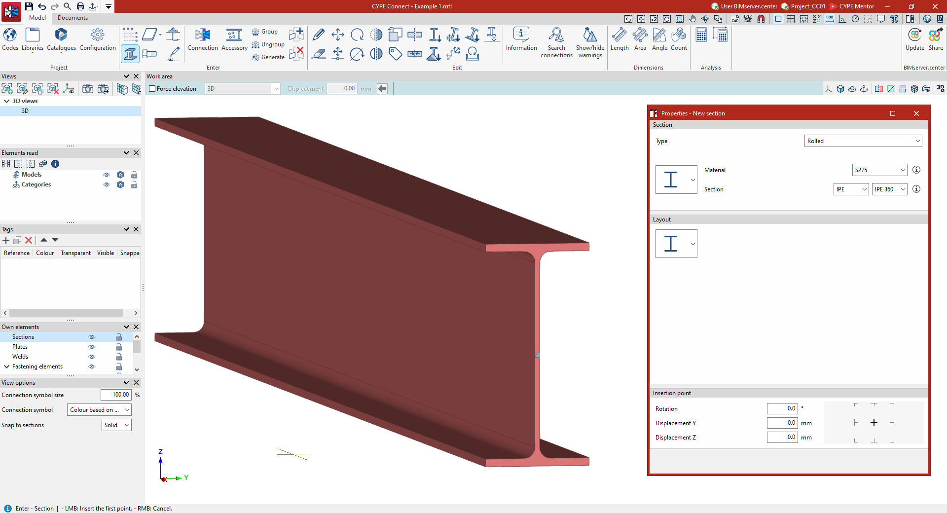
The section is defined by its start and end points; therefore, to insert it, you must select two points on the model using the left mouse button. You can control the position of the points using the various options for inserting elements in the workspace.
To help with these points, there are various tools available, such as the following:
- You can snap to the lines of a previously defined "Grid"
- To snap points from other elements already included in the model, check that these are selectable in the visibility options on the left-hand side and use the "Object reference" option.
- It is also useful to click on the "Allows dimensions to be defined as each element is entered" option so that you can enter the "Length" value for the section as you type it in.
- Furthermore, the "Orthogonality" option forces the section direction when it is entered.
- If required, you can work using the "Coordinate entry" method.
Additionally, if a template has been imported into the program, the "Template object snaps" available on the top toolbar are used.
Further sections can be entered by left-clicking on other points. Simply right-click the mouse to complete the operation and exit the command.
Available sections and layouts
The program offers the following sections and settings for each material, within the properties definition window accessible when creating or editing a section, on the "Model" tab.
Rolled


- Rolled I
- Simple section
- With lateral plates
- Double in box with batten plates
- Double (Separation between sections)
- Double welded in box
- Simple with haunches
- Simple U
- Simple section
- Double in box with cover plates (between the flanges)
- Double in box with cover plates (between the flanges) and Variable depth
- Double in box with batten plates
- Double welded in box (Separation between sections)
- Double welded in box
- I-shaped double with loops
- Double I-beam (Separation between sections)
- Double welded in I
- Angle
- Simple section
- Four in box generic joint
- Four in cross
- Four in I
- Double welded (Separation between sections)
- Double welded in T
- Double U-shape (Separation between sections)
- Double welded in box
- Double in box (Separation between sections)
- Plate
- Simple section


- T-section
- Simple section
- Square bar
- Simple section
- Round bar
- Simple section
Built-up section with rolled steel plates


- Universal beam
- Simple section
- I section with variable depth
- Simple section
- Simple U
- Simple section
- Rectangular box
- Simple section


- T-section
- Simple section
- Plate
- Simple section
Cold-formed


- Simple cold-formed C
- Simple section
- Double in box (Separation between sections)
- Double welded in box
- Double in I (Separation between sections)
- Double welded in I
- Stiffened cold-formed C
- Simple section
- Double in box (Separation between sections)
- Double welded in box
- Double in I (Separation between sections)
- Double welded in I
- Simple cold-formed Z
- Simple section
- Cold-formed Z with stiffeners
- Simple section


- Cold-formed angle
- Simple section
- Double cross section (Separation between sections)
- Double welded in T (Separation between sections)
- Stiffened cold-formed angle
- Simple section
- Double cross section (Separation between sections)
- Simple Omega sloped webs
- Simple section
- Omega sloped in external depth
- Simple section


- Stiffened Omega sloped webs
- Simple section
- Channel with stiffened web
- Simple section
Tubular


- Circular hollow section
- Simple section
- Double
- Quadruple
- Rectangular hollow section
- Simple section
- Double
- Quadruple
Timber
- Rectangular section
- Simple section
Connections with built-up sections
As well as allowing you to design connections between different simple sections (either laminated, shaped, reinforced or timber), the program allows you to design and analyse connections with built-up sections made up of several sections.
Unlike the definition using several simple bars, built-up sections allow the program to work with a single set of forces for the entire bar.
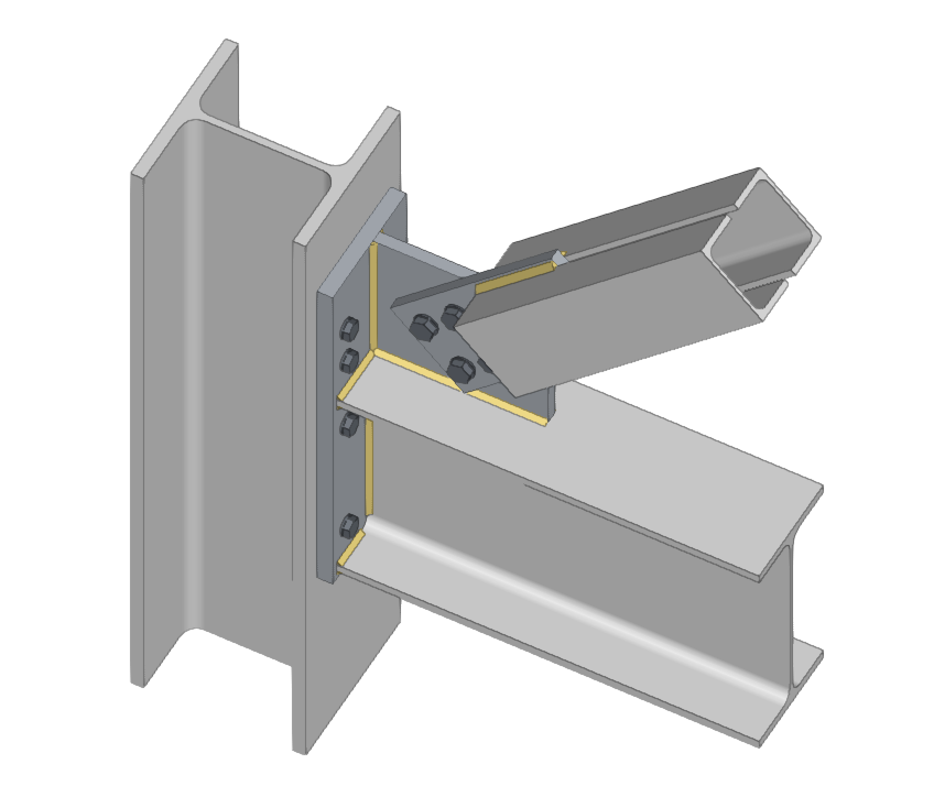
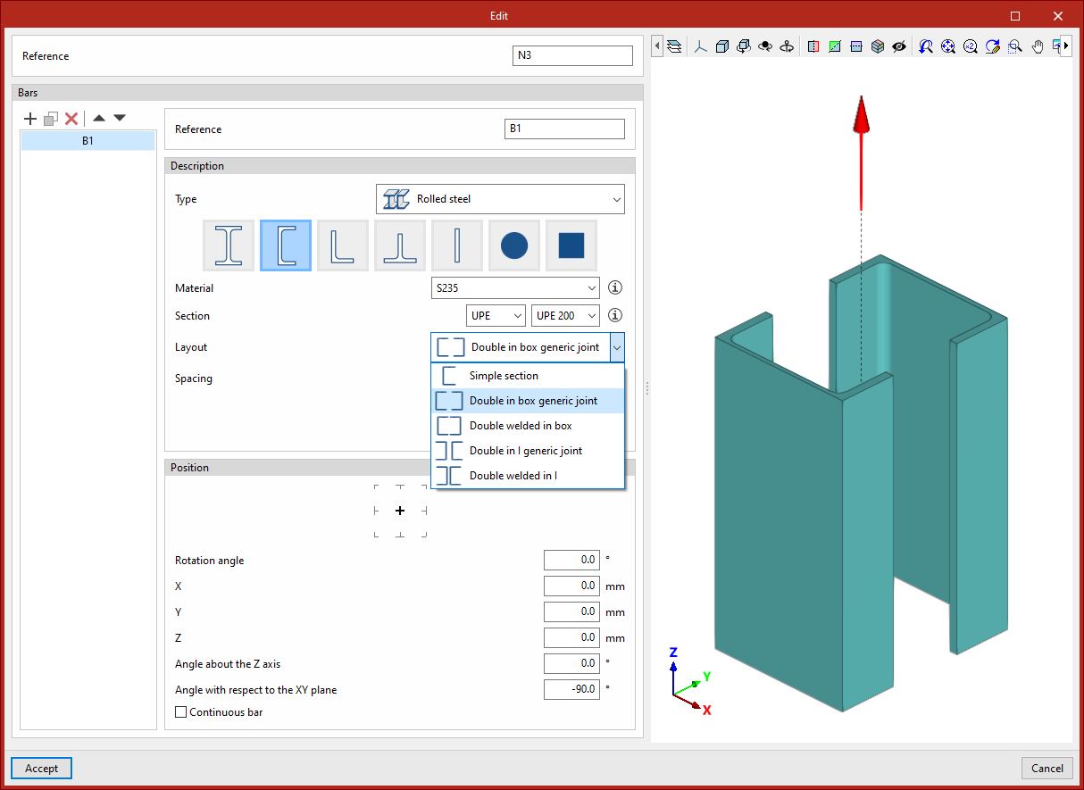
The sections implemented are as follows:
Rolled steel I section:
- Double in box generic joint
- Double welded in box
Rolled steel channel section:
- Double in box generic joint
- Double welded in box
- Double in I generic joint
- Double welded in I
Rolled steel angle section:
- Double in box generic joint
- Double welded in box
- Double in T generic joint
- Double welded in T
- Double in U generic joint
- Four in box generic joint
- Four in cross generic joint
- Four in I generic joint
Cold formed steel channel section:
- Double in box generic joint
- Double welded in box
- Double in I generic joint
- Double welded in I
Rigidi section of shaped steel channel:
- Double in box generic joint
- Double welded in box
- Double in I generic joint
- Double welded in I
Formed steel angle section:
- Double in T generic joint
- Double in cross generic joint
Rigid angular section made of shaped steel:
- Double in cross generic joint
Rectangular hollow section:
- Double with generic joint
- Four with generic joint
Circular hollow section:
- Double with generic joint
- Four with generic joint
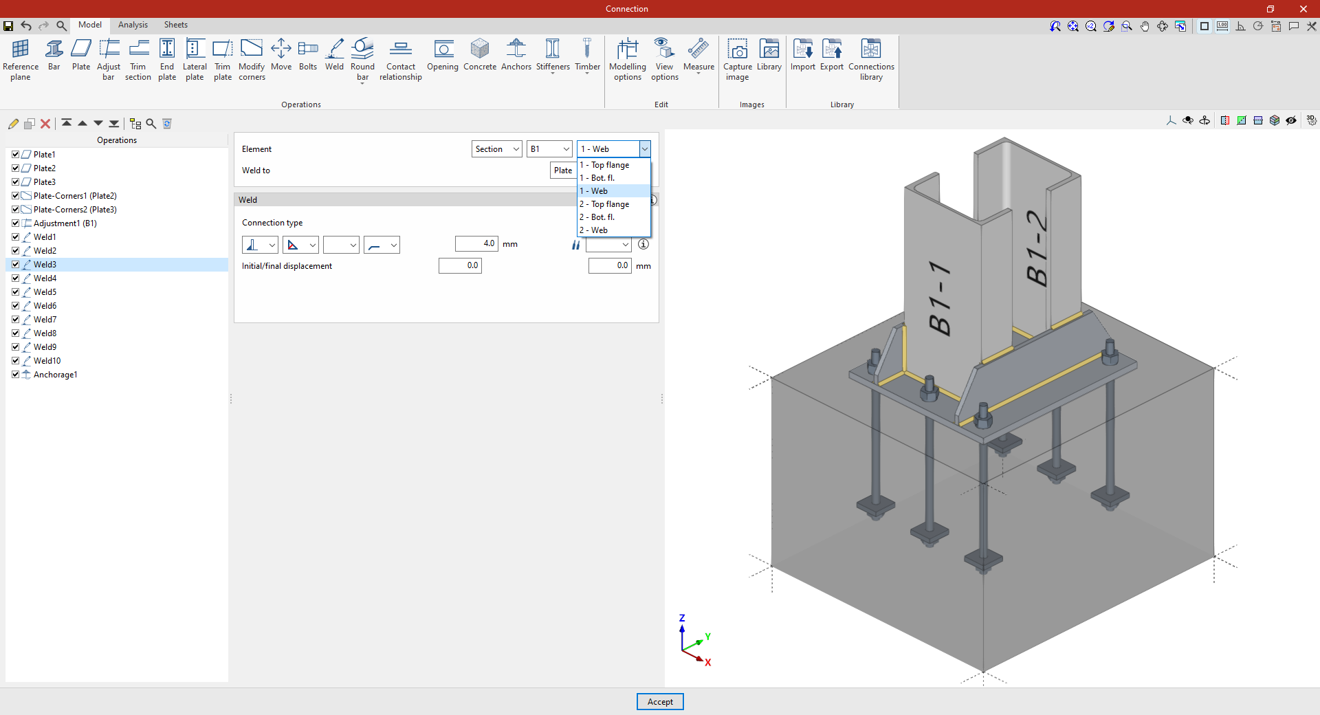
During the design of the connection, each part of the bar will be identified. To model the application of loads at the ends of composite bars, the same procedure is followed as for simple bars.
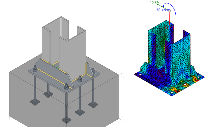
With regard to the analytical model, the end nodes of all sections comprising the bar shall be connected by means of fictitious rigid elements to the fictitious load application node (located at the centre of gravity of the built-up section).
Entering plates
To insert plates into the general model of the structure, on the "Model" tab of the program interface, select the "Plate" option from the "Insert" group on the top toolbar.

Plate
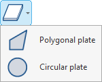
After clicking on the "Plate" option, a menu appears where you can choose whether to insert a "Polygonal plate" or a "Circular plate".
| Note: |
|---|
| This tool allows you to freely insert plates to complete the breakdown of the structure at specific points. However, if the aim is to model connections, including their analysis and compliance checks, it is advisable to use the "Joint" option instead, where it is also possible to insert plates using the specific operation. |
Polygonal plate
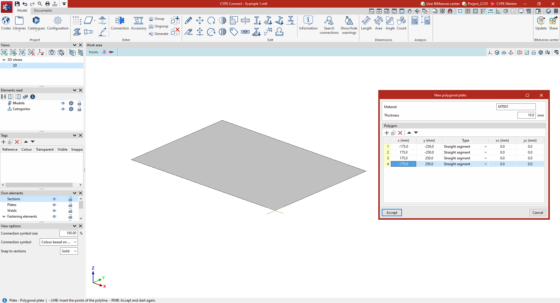
For a "Polygonal plate", you must select the points that define the perimeter of the polygon in the model using the left mouse button. Then, click the right mouse button.
This brings up the "New polygonal plate" window, where the "Material" and "Thickness" of the plate are defined. In the table below, you can review the "Polygon" data defining the plate, including the local "x" and "y" coordinates of the vertices, the "Type" of each segment – either a "Straight section" or a "Curved section" – and, if necessary, the coordinates of the centre of the curve, "xc" and "yc".
Next, click on "Accept" to confirm this information.
Circular plate
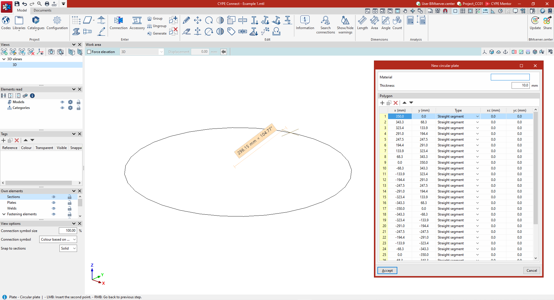
For a "Circular plate", you must use the left mouse button to select the centre and the radius of the circle that defines its perimeter on the model. Then, click the right mouse button.
This brings up the "New circular plate" window, with options equivalent to those mentioned above. In the table below, the program will have generated a regular "Polygon" made up of straight segments that approximates the circle entered.
Finally, click "Accept" to confirm this information.
Editing plates and entering modifiers
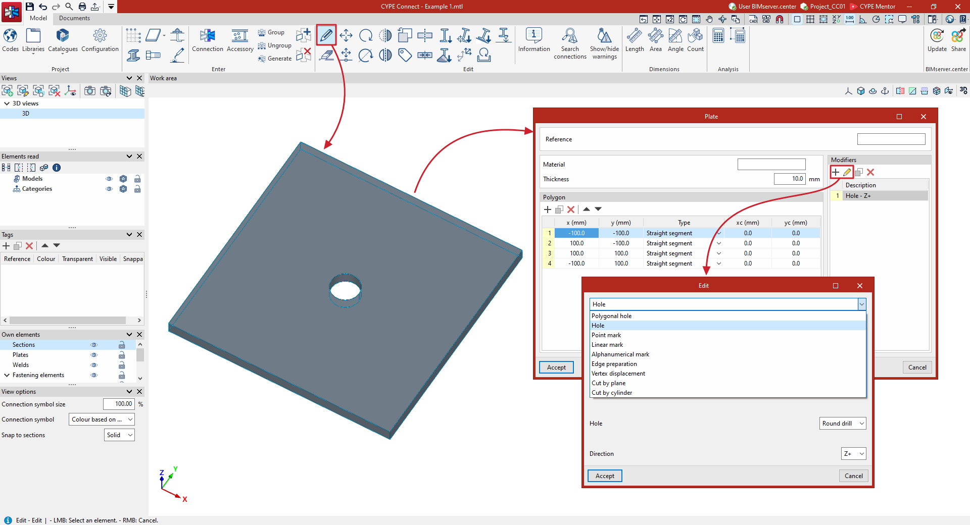
If required, use the "Edit" option in the "Edit" group on the top toolbar to modify or complete the definition of the plates.
After left-clicking on one of them, the "Plate" window opens, where you can enter its "Reference" and edit the details for the "Material", "Thickness" and "Polygon" of its outline.
Furthermore, in the table on the right, you can enter one or more "Modifiers" for the plate. After clicking "Add", a window opens where you can define the "New" modifier by selecting it from the drop-down menu.
The following options are included:
- Entering a "Polygonal hole"
- Entering a "Hole"
- Adding a “Point marker”, a “Line marker” or an “Alphanumeric marker”
- Defining an "Edge preparation", a "Vertex displacement", a "Cut by plane" or a "Cut by cylinder".
The program offers various options for adjusting the settings for each of these modifiers.
Finally, to finish editing the plate, click "Accept".
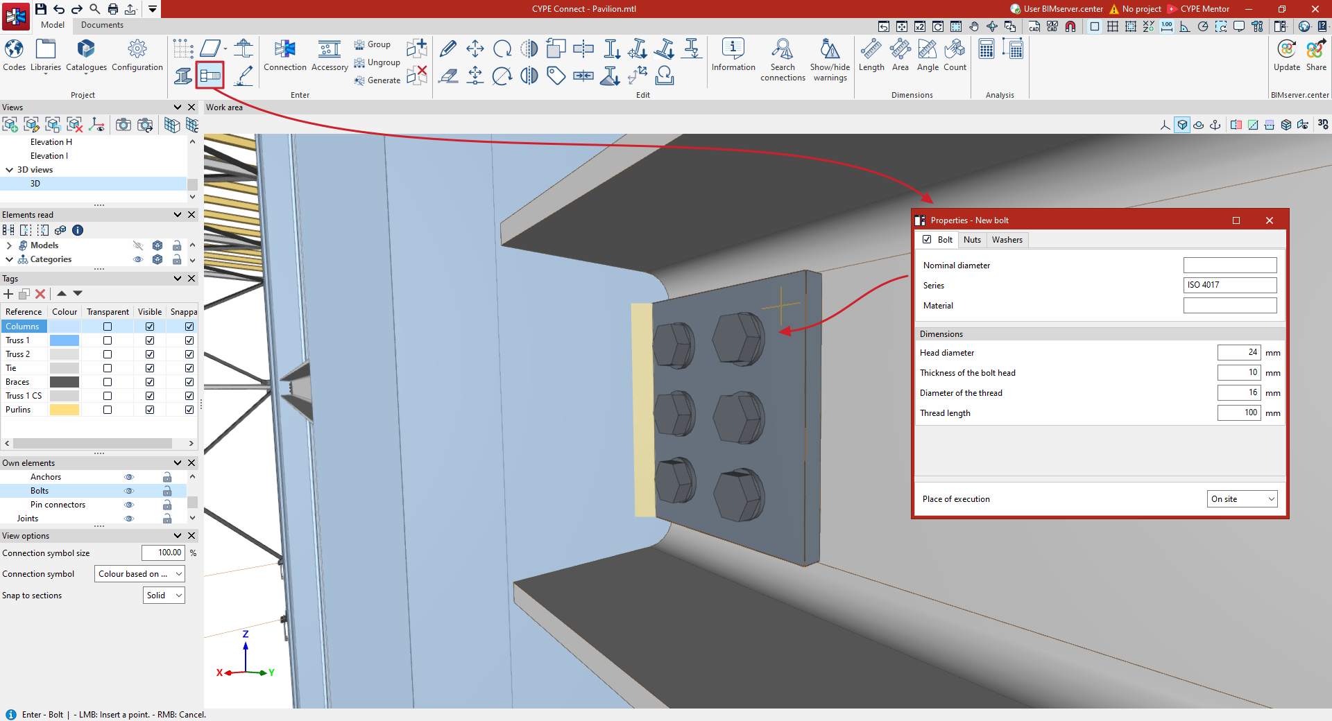
Inserting bolts
To insert bolts into the general model of the structure, in the "Model" tab of the program interface, select the "Bolt" option from the "Enter" group on the top toolbar.

Bolt
After clicking on the "Bolt" option, a window appears where you can define the properties of the new bolt.
| Note: |
|---|
| This tool allows bolts to be freely inserted to complete the structure’s detail drawing at specific points. However, if the aim is to model connections, including their calculation and code compliance checks, it is advisable to use the "Connection" option instead, where bolts can also be inserted using the specific operation. |
Defining bolt properties
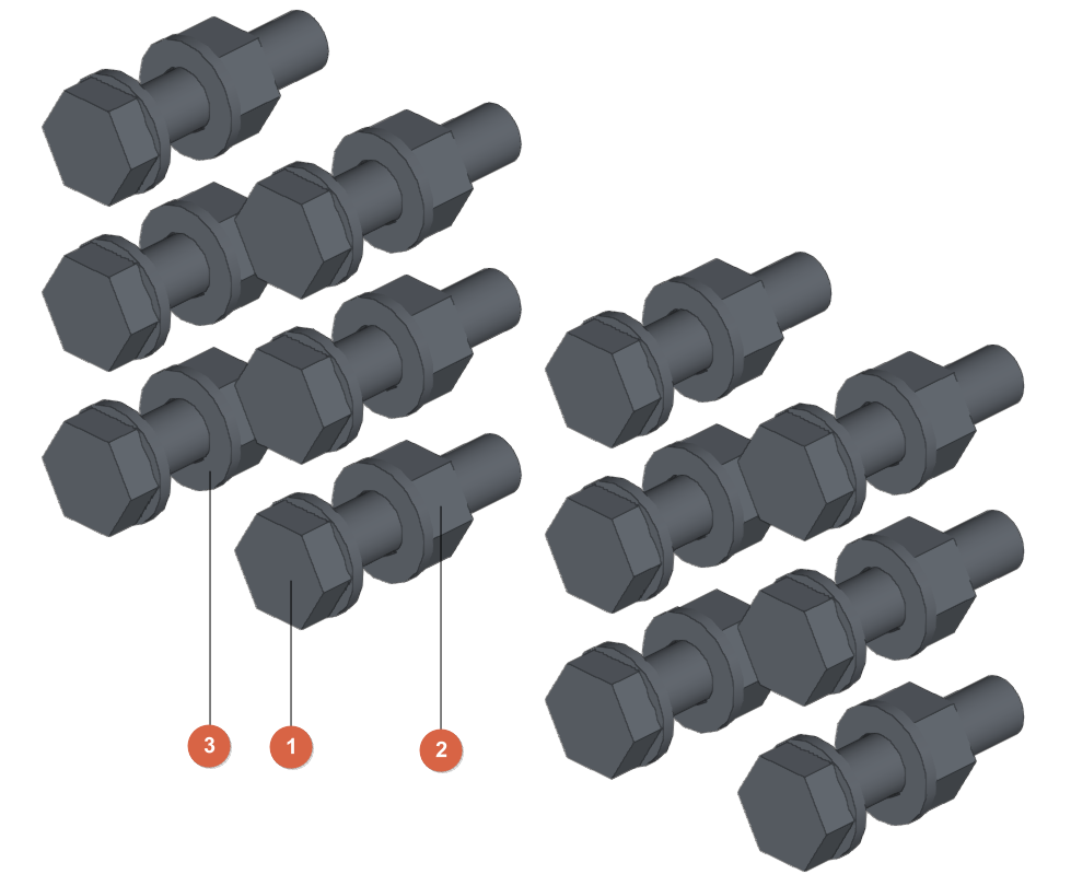
The various tabs available show details of the "Bolt" itself (1), the "Nuts" (2) and the "Washers" (3), where applicable.
Further down, in the drop-down menu at the bottom, you can select whether the "Installation location" is "On site" or "In the workshop".
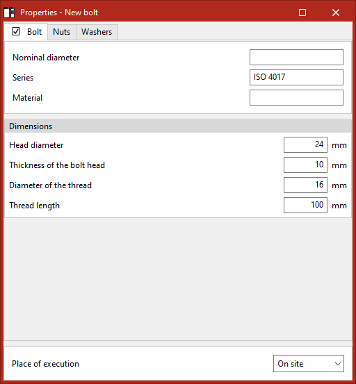
"Bolt" tab
To define the bolt itself, select this tab and enter the "Nominal diameter", the "Series" and the "Material", as well as the "Dimensions" for the following parameters:
- Head diameter
- Thickness of the bolt head
- Diameter of the thread
- Thread length
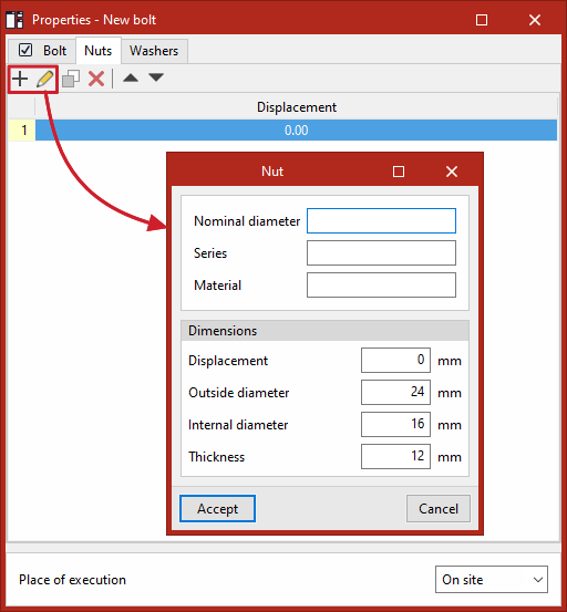
"Nut" tab
To define the nuts and/or locknuts, entries must be added to a table in which they are listed with their "Displacement" value, which indicates the distance between each nut and the base of the bolt head.
For each nut, the reference number for its "Nominal diameter", "Series" and "Material" is entered, along with the "Dimensions" for the following parameters:
- Displacement
- Outer diameter
- Inner diameter
- Thickness
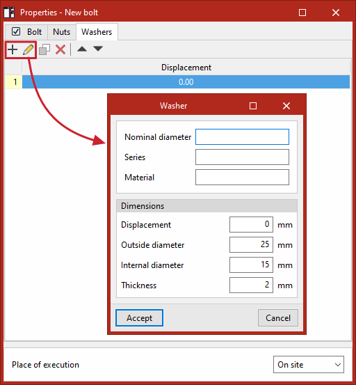
"Washers" tab
To define the washers, entries must be added to a table in which they are listed along with their "Displacement" value, which indicates the distance between each washer and the base of the bolt head.
For each washer, the reference for its "Nominal diameter", "Series" and "Material" is entered, as well as the "Dimensions" for the following parameters:
- Displacement
- Outside diameter
- Internal diameter
- Thickness
Placing bolts in the work area
To insert the bolt into the model, use the left mouse button to select a group of elements one by one or to highlight a selection area. Then, click the right mouse button to confirm the selection.
The program now allows you to position the bolt by placing the cursor on any of the faces of the selected elements. Clicking the left mouse button inserts the bolt.
From here, you can insert new bolts with the same properties by left-clicking again at other points on the selected elements in the model.
The "Properties" window remains open in case you wish to make any changes to these settings. These changes will apply to any new bolts added after they have been modified.
Finally, you can right-click to deselect the group of elements, and if you right-click again, the operation is completed.
Entering anchors
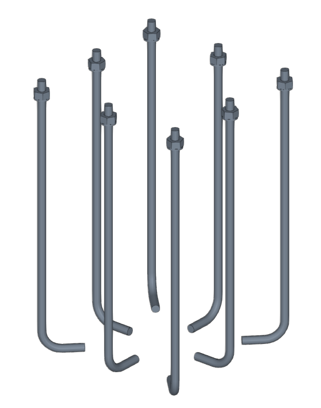
To add fixings to the general structural model, on the "Model" tab of the program interface, select the "Anchor" option from the "Enter" group on the top toolbar.

Anchor
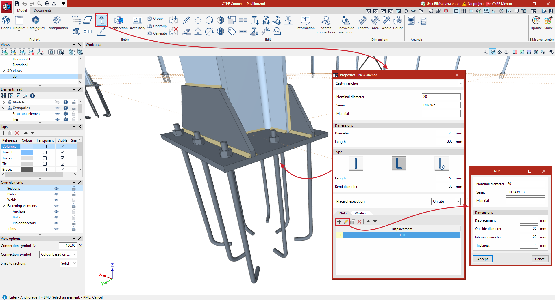
After clicking on the "Anchor" option, a window appears where you can define the "Properties of the new anchor".
| Note: |
|---|
| This tool allows you to enter anchors freely to complete the structural breakdown at specific points. However, if the aim is to model connections, including their analysis and compliance checks, it is advisable to use the "Connection" option instead, from which you can also enter anchors. |
Defining the properties of anchors
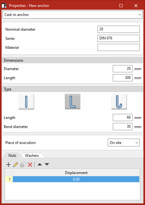
First, select from the drop-down menu at the top whether it is a "Cast-in anchor" or a "Post-installed anchor".
Cast-in anchor
In the case of a pre-installed anchor, the "Nominal diameter", "Series" and "Material" of the anchor are entered.
To specify their "Dimensions" in the following section, their "Diameter" and "Length" are given.
Next, select the "Type" of anchor. This can be a "Straight anchor", an "Anchor with 90° bend" or an "Anchor with 180° hook". In the latter two cases, the "Length" of the tab or hook and the "Bending diameter" must be specified.
In the drop-down menu below, select whether the "Installation location" is "On site" or "In the workshop".
Finally, you can add "Nuts" or "Washers" in the tables accessible via the tabs at the bottom.
Here, you must "Add" elements to the table to define the properties of each individual "Nut" or "Washer".
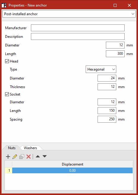
Post-installed anchor
In the case of a post-installed anchor, enter the "Manufacturer" and its "Description", as well as the "Diameter" and "Length" of the anchor.
Optionally, tick the "Head" box to specify its characteristics, such as the "Type" (whether "Hexagonal", "Cylindrical", "Square", "Hemispherical" or "Countersunk"), its "Diameter" and "Thickness".
Similarly, you can optionally tick the "Socket" box to specify its "Diameter", "Length" and "Spacing".
Finally, you can add "Nuts" or "Washers" in the tables accessible via the tabs at the bottom.
Here, you need to "Add" elements to the table to define the properties of each individual "Nut" or "Washer".
Entering anchors in the work area
To enter the anchor into the model, select an element (such as a plate or a section) using the left mouse button.
The program now allows you to position the anchor by placing the cursor on any of the faces of the selected element. Clicking the left mouse button sets the anchor.
From here, you can add new anchor points with the same properties by left-clicking again at other points on the element.
The "Properties" window remains open in case you wish to make any changes to these settings. These changes will apply to any new anchors added after they have been modified.
Finally, you can click the right-hand button to deselect the element, and clicking it again will complete the operation.
Entering welds
To add welds to the general model of the structure, in the "Model" tab of the program interface, select the "Weld" option from the "Insert" group in the top toolbar.

Welds
Entering welds in the workplace
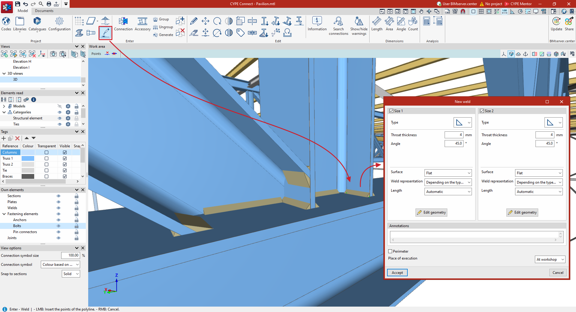
After clicking on the "Weld" option, you must select the two elements to be welded in the model using the left mouse button.
Next, use the left mouse button to enter the points of the polyline that defines the position of the weld.
Clicking the right-hand button validates the geometry entered and brings up a window where you can define the properties of the "New weld".
| Note: |
|---|
| This tool allows you to enter welds freely to complete the detailing of the structure at specific points. However, if the aim is to model connections, including their analysis and compliance checks, it is advisable to use the "Connection" option instead, from which you can also enter welds. |
Defining weld properties
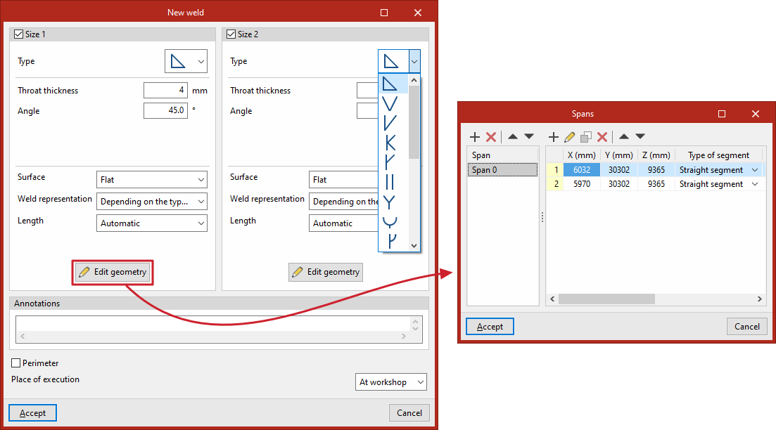
At the top, the "Size 1" or "Size 2" tick boxes are selected to indicate whether they exist and specify the data for each side of the weld bead.
Select the "Type" of weld from the drop-down menu containing the standard symbols and adjust its parameters. For a fillet weld, for example, enter the "Groove depth" and the "Angle".
Next, you select whether the shape of the weld’s "Surface" is "Undefined", "Flat", "Concave", "Convex" or has "Smooth transition curves"; you also specify the "Weld representation" in the model, which can be "According to bead type" or "Approximate"; and its "Length", which can be either "Automatic" or "User-defined".
From the "Edit geometry" menu, you can view each of the welding “Sections” that have been entered in a series of tables and modify the coordinates and characteristics of the segments that make them up.
You can add a "Notes" text in the field below if necessary.
Next, tick the box if the weld is "Perimeter" and, in the last drop-down menu, select whether the "Installation location" is "On site" or "In the workshop".
To validate the data entered, click "Accept".
You can select another pair of elements if you wish to add new welds. If, on the other hand, you wish to finish the operation, click the right-hand button.
Entering and editing connections
To define connections between sections, on the "Model" tab of the program's main interface, select the "Connections" option from the "Enter" section on the top toolbar.

Connection
Creating new connections
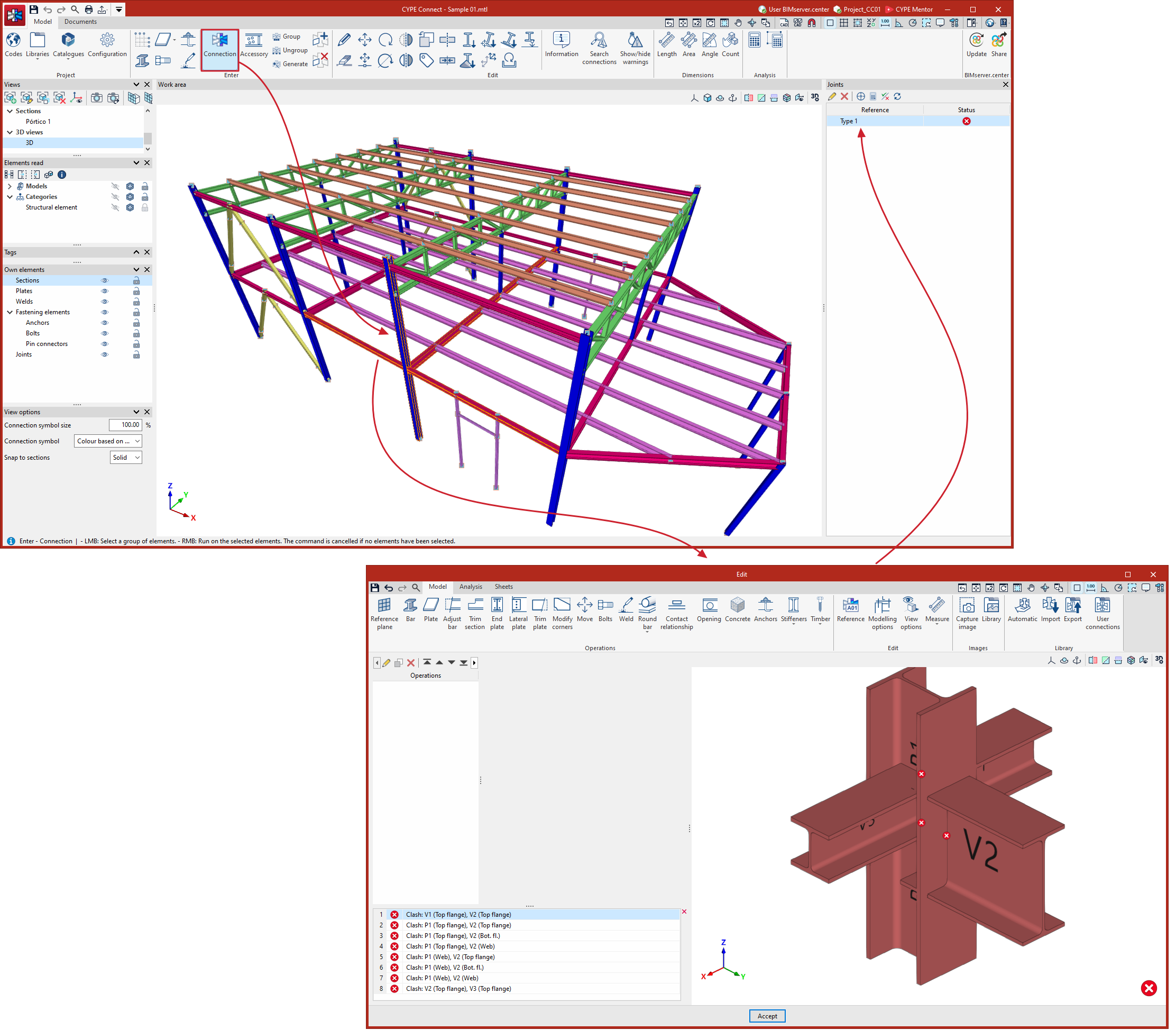
To create new connections, click on the "Connection" option, and first select the bars involved in the connection using the left mouse button (i.e. the bars that connect to the same node) or, after selecting the first bar, draw a selection area to select the remaining bars.
Only some of the bars connected to a node may be selected to create a partial connection between them.
If a bar passes through the node, it will be treated as continuous.
You can also select only the initial or final end point of a bar if you want to resolve the connection at that point, as in the case of a baseplate.
Right-clicking after selecting the bars opens the "Connection" editing window or connection editor.
When you click "Accept" or close the edit window on any of its tabs, the program updates the connection information and returns to the main program interface. The connection you have created will also be added to the "Connection" table, which is displayed by default in the right-hand side panel of the interface.
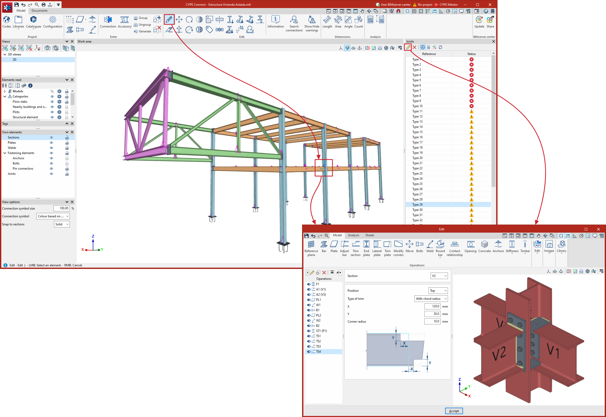
Options for editing connections
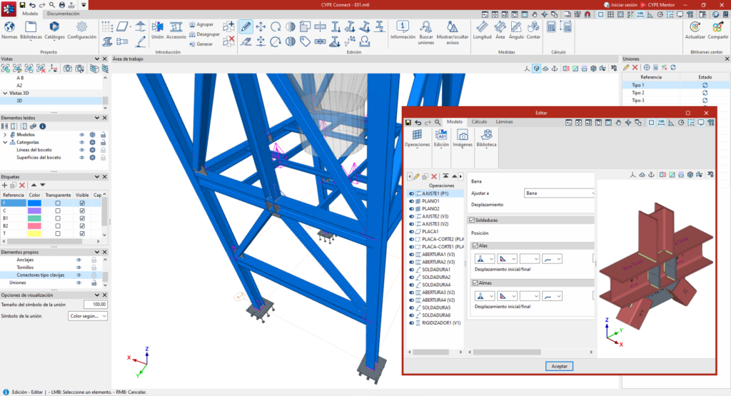
You can edit a connection that has already been created from the "Edit" section of the top toolbar, using the "Edit" option.
The symbol used to represent connectors is a purple pyramid, as opposed to the blue pyramid used for fittings.
Clicking on a specific connection with the left mouse button opens the "Connection" editing window, or connection editor.
You can also edit a connection by selecting it from the table or the "Connection" list in the right-hand sidebar and clicking the "Edit" button on the toolbar at the top of the table.
Entering and editing fittings
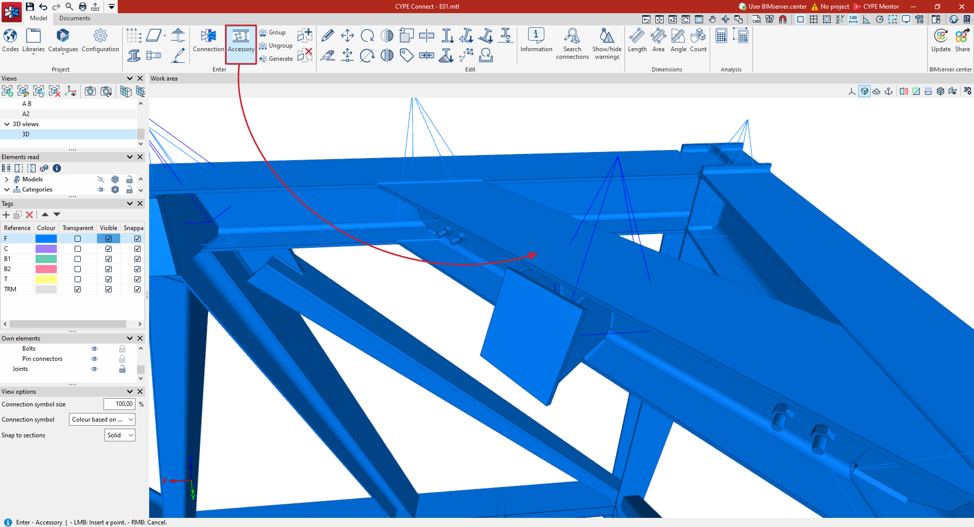
To create a fitting on a section, on the "Model" tab of the program’s main interface, select the "Fitting" option from the "Enter" section on the top toolbar.

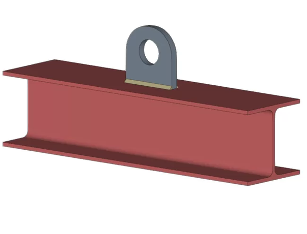
Fittings are components fitted at intermediate points along profiles, such as drill holes, openings, reinforcements or lifting lugs.
Fitting
Designing new fittings
To create a new fitting, click on the "Fitting" option and then left-click on the point on a beam where you wish to insert the fitting. You can use snaps and relevant object references to help you position this point.
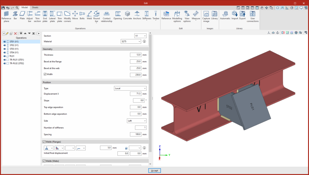
This opens the "Fittings" editing window. The fitting modelling interface is similar to that used for editing connections. Further information on the connection editor can be found at this link.
When you click "Accept" or close the edit window on any of its tabs, the program updates the fitting information and returns to the main program interface. The newly created fitting will also be added to the "Connections" table, which is displayed by default in the right-hand side panel of the interface.
At this point, you can continue to select other points using the left mouse button to add more fittings of the same type to the model. To finish adding a specific group of fittings, click the right mouse button.
Options for editing fittings
To edit a fitting that has already been created and to familiarise yourself with the main functions of this editing interface, select the "Edit" option in the "Edit" section of the top toolbar.
The symbol used to represent fittings is a blue pyramid, as opposed to the purple pyramid used for joints.
Clicking on a specific fitting with the left mouse button opens the edit window for the connection editor, which in this case has only two tabs: "Model" and "Sheets".
You can also edit a fitting by selecting it from the "Connections" table or list in the right-hand side panel and clicking the "Edit" button on the toolbar at the top of the table.
Connection editor
The connection editor features an interface with three tabs at the top: "Model", "Analysis" and "Sheets":
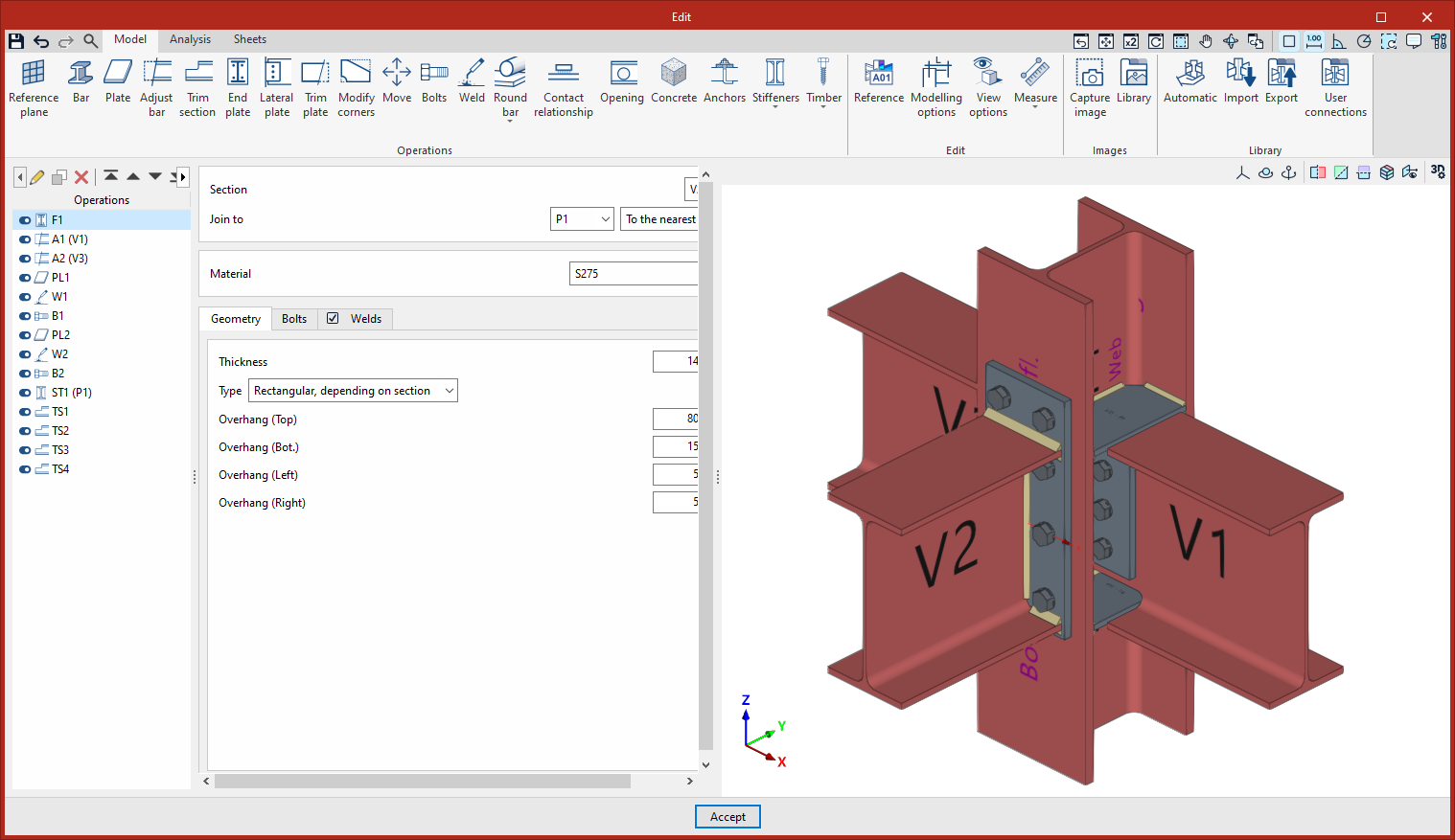
Model
On the first tab, "Model", you can carry out the complete modelling of the connection, adding and modifying its various components.
Connection elements can be entered or adjusted through a series of operations, as well as by importing connection types from the connection libraries or using parametric connections.
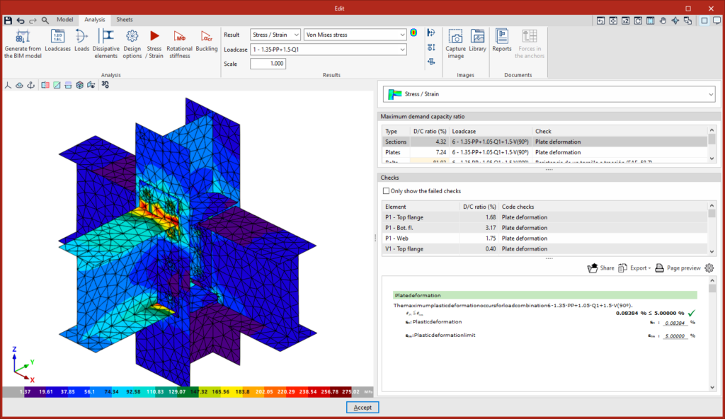
Calculation
Once the model has been completed, you can access the "Analysis" tab, where the analysis and verification of the connection are carried out.
The available analyses include the stress-strain analysis, rotational stiffness analysis and buckling analysis. The program displays the analysis results in the built-in viewer and provides detailed lists of checks against standards.
This tab is not available when editing fittings.
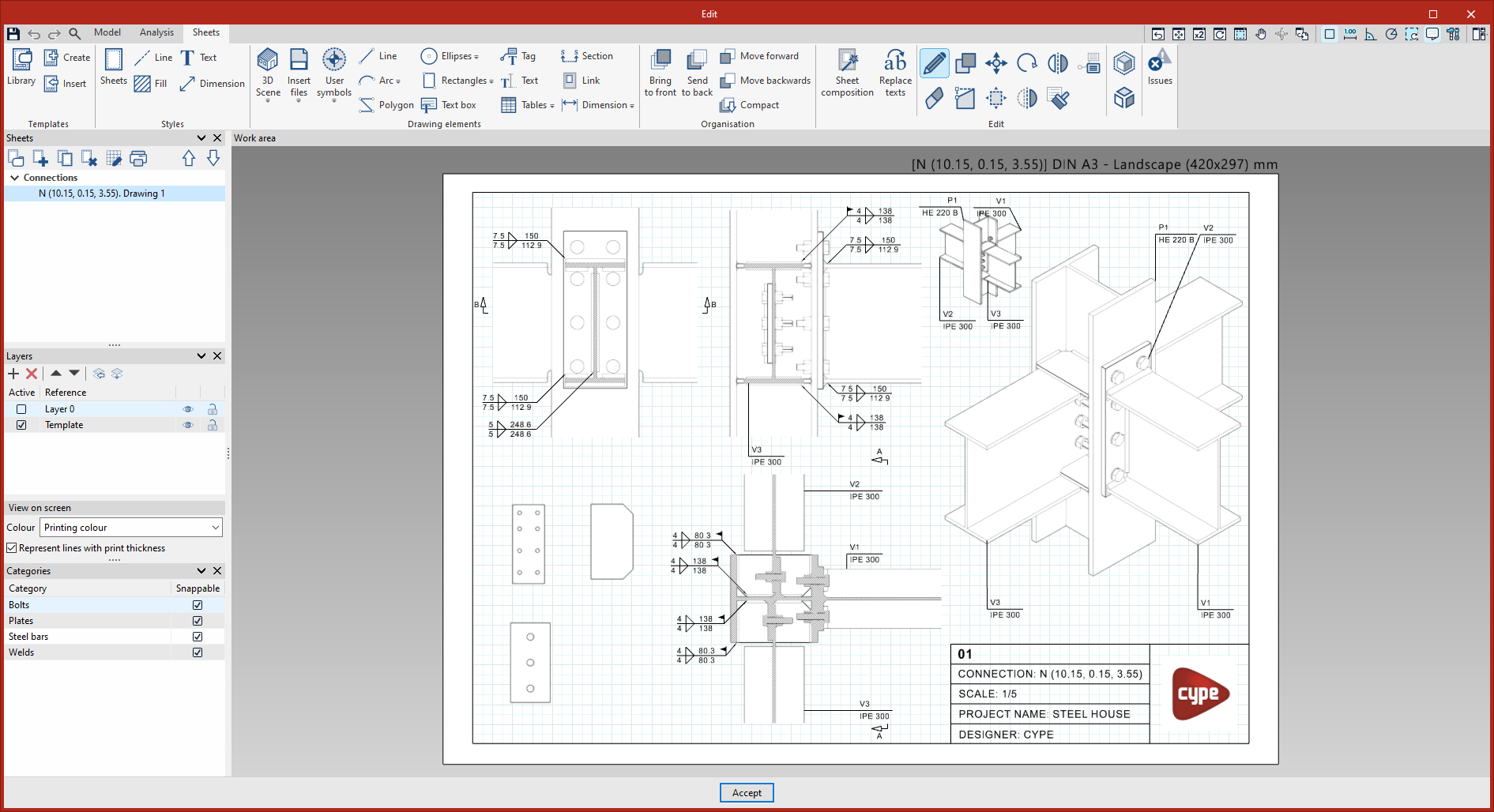
Prints
Once you have modelled and analysed a connection, you can move on to the "Sheets" tab, where you will find the tools for creating detail drawings.
Alternatively, you can access this interface for working with connection sheets from the "Documents" tab in the main interface by selecting the "Connections" option from the "Sheets" section.
Here, you can create views of the connection model at the desired scale, which are dynamically linked to the model. The program also features traditional drawing tools and design tools.
Grouping and ungrouping connections
To group and ungroup connections, from the "Model" tab on the program's main interface, use the relevant options in the "Enter" section of the top toolbar.

A group of nodes will be assigned the same connection. The connection assigned to a group of nodes will read the bar forces for all nodes in that group from the BIM project. The combination filter applied via "Generate from the BIM model" is based on the sum of the combinations for all nodes.
Group
The "Group" option is used to group identical connections.
Once you have selected this option, when you hover the pointer over a connection, all those that are identical and belong to the same group will be highlighted in blue. When you left-click, the group is selected and its colour changes to orange.
You can then select other connections with the same characteristics, which will be highlighted in yellow. To add them to the group of connections, left-click on them and then right-click to confirm.
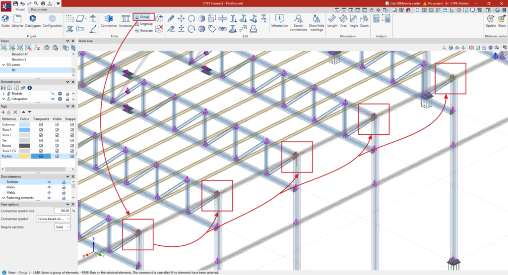
Ungroup
The "Ungroup" option allows you to ungroup previously grouped connections. To do this, left-click on the connection you wish to remove from the group. Then, confirm by right-clicking.
Automatic generation of connections
The following option, available in the "Enter" section of the "Model" tab, is used to generate model connections automatically and also to group them and/or define them in detail based on the available connection libraries:

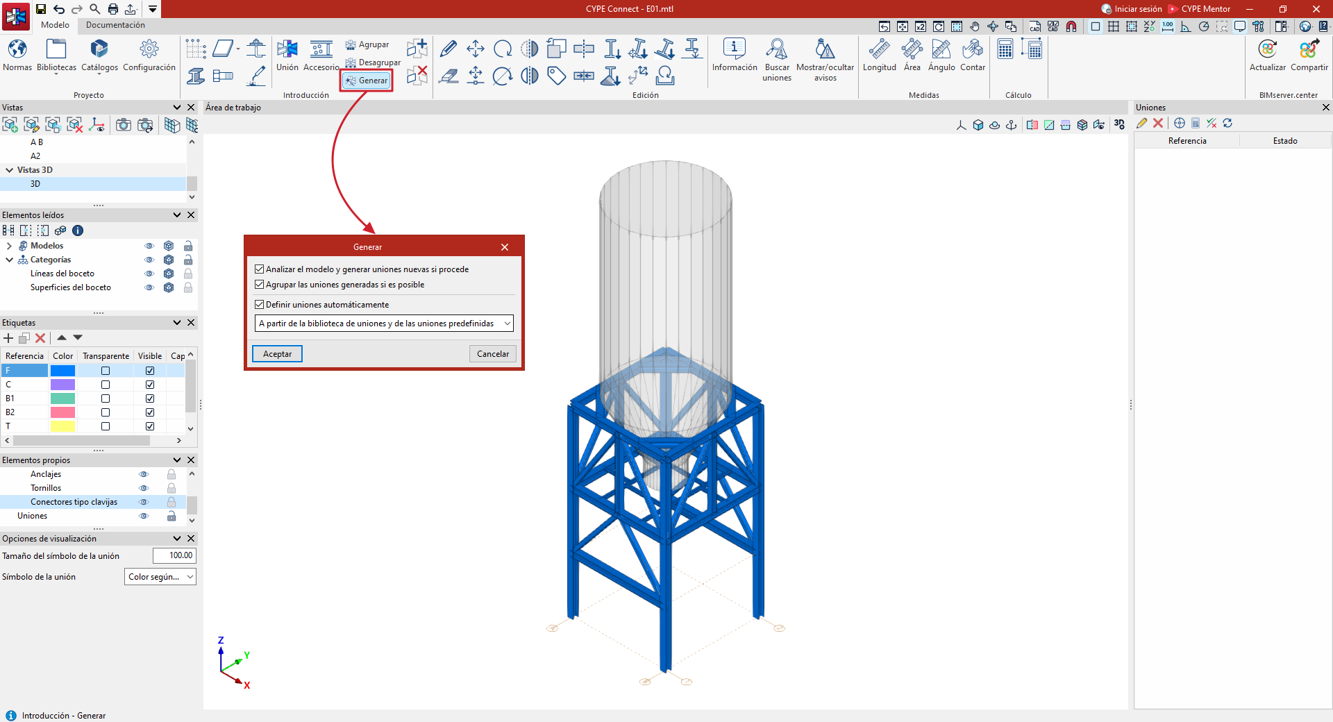
Generate
When you click on the "Generate" option, a window appears with the following options:
- Analyse the model and generate new joints if necessary (optional)
If this option is selected, the program will create and add connections to the list, positioned correctly based on the model data. If the following options are not selected, connections will be generated without being grouped and without defined operations. - Group generated connections where possible (optional)
This option appears if the previous one is enabled. When enabled, the generated connections will be automatically grouped according to their characteristics. - Define connections automatically (optional)
Selecting this option defines the necessary operations for joints where this is possible, based on the information available in the connection libraries. Both previously created connections and those generated during the process initiated by clicking the "Generate" option will be defined. Select one of the following options from the drop-down menu to specify whether the connections are defined:- From the user's connection library
- From the predefined connections
- Or simultaneously
When clicking "Accept", the program will display the number of connections generated in an “Information” box.
| Note: |
|---|
| Defining automatic connections for the entire project is the same as using the "Automatic" option for each connection, which is available in the connection editing window. The following link describes the use and scope of the predefined connection libraries. |
Options for adding and removing sections from a joint
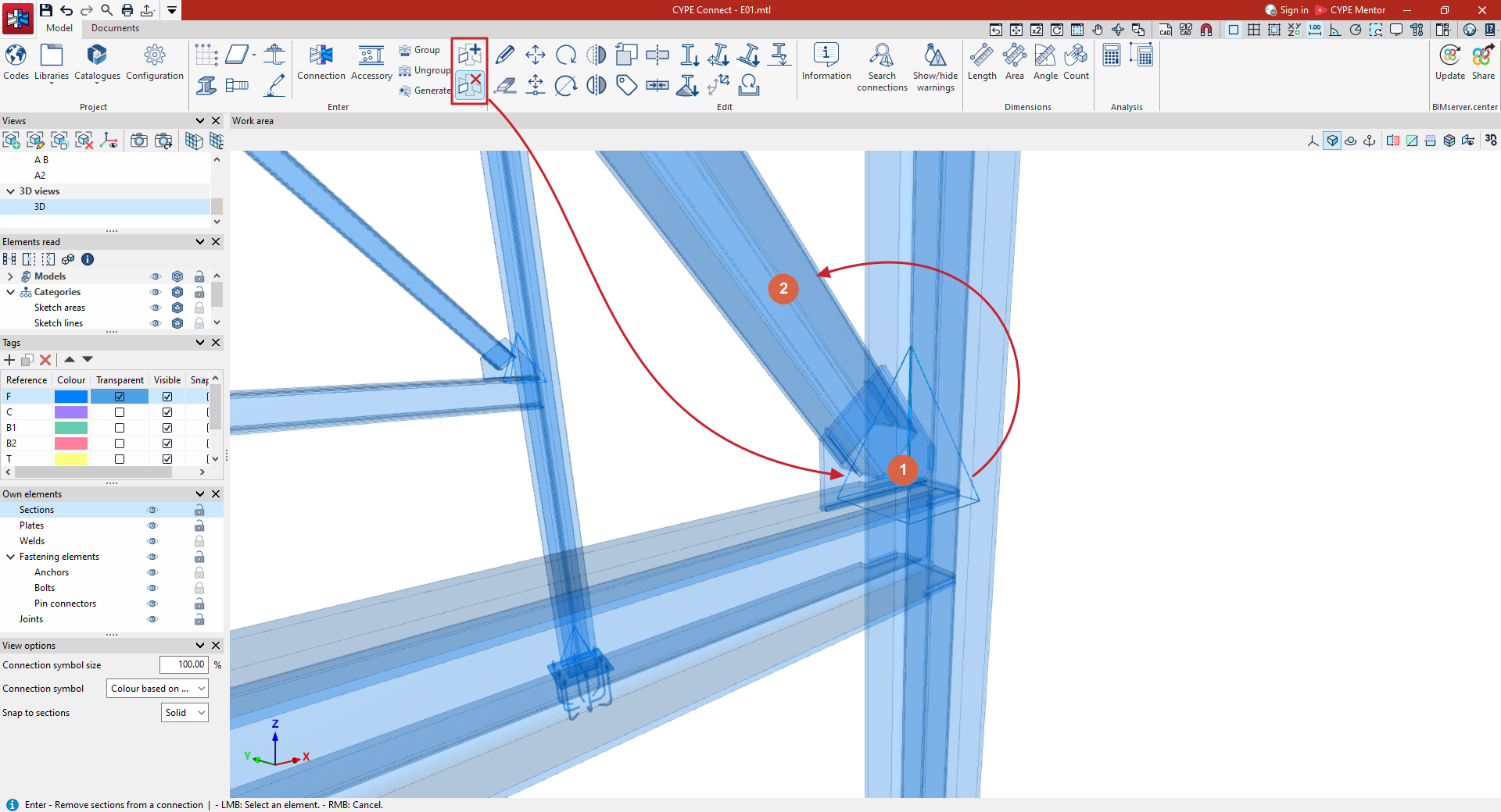
The following tools, available in the "Enter" section of the top toolbar on the "Model" tab of the program's main interface, allow you to add sections to a joint or remove sections from a previously defined joint.

Add sections to a joint
To "Add sections to a joint", click on this option, and then:
- Use the left mouse button to select the joint to which you wish to add sections.
- Use the left mouse button to select the sections you wish to add to the joint one by one.
- Confirm the operation by clicking the right-hand button.
Remove sections from a joint
To "Remove sections from a joint", click on this option, and then:
- Left-click to select the joint where you want to remove sections.
- Use the left mouse button to select, one by one, the sections you want to remove from the joint.
- Confirm the operation by clicking the right-hand button.
Editing tools in the "Model" tab
The tools for editing the general structure model are located in the "Edit" group on the top toolbar, within the "Model" tab of the program’s main interface:

 | Edit | Select an element in the model and edit its parametric properties. After clicking on the option, you can hover the pointer over the elements in the model; those that can be selected will be highlighted in blue. When you left-click on an element, the program will open the editing window. |
 | Delete | Delete one or more previously selected elements. After clicking on the option, select the elements one by one using the left mouse button or by dragging to select an area; the program will highlight them in orange. Right-click to delete them. |
 | Moving a group of elements | Move a group of elements. After clicking on the option, select the elements using the left mouse button and confirm the selection with the right mouse button. Then, use the left mouse button to mark two points that define the start and end of the displacement. |
 | Move | Move the point of a single element. After selecting this option, click on the element you wish to move, then click the left mouse button to select the point you wish to move. Next, click the left mouse button again to specify the new position of the selected point. |
 | Rotate | Rotate a group of elements. After clicking on the option, select the elements using the left mouse button and confirm the selection with the right mouse button. Next, mark the centre and angle of rotation by selecting two points with the left mouse button. The plane of rotation will follow the working plane defined in the view where the operation is being carried out. |
 | Rotate about an axis | Rotate elements about an axis. After clicking on the option, first select the elements using the left mouse button. After confirming with the right mouse button, mark two points to define the axis of rotation. Then, enter the "Rotation angle" and confirm by clicking on the green tick. |
 | Symmetry (move) | Move the selected elements symmetrically about a vertical plane defined by two points. To do this, after selecting the elements with the left mouse button and confirming with the right mouse button, select two points that define the plane of symmetry. |
 | Symmetry (copy) | Copy a selection of elements symmetrically with respect to a vertical plane defined by two points. To do this, select the elements using the left mouse button, confirm the selection with the right mouse button, and then mark two points that define the plane of symmetry. In this case, after the symmetry operation, the original elements remain in the model. |
 | Copy | Create copies of one or more elements. After selecting them with the left mouse button and confirming the selection by right-clicking, use the left mouse button to mark the start point and end point that define the distance the copy will be moved. You can left-click on further points in succession to generate more copies of the selected group of elements. |
 | Assign tags | Assign the tags from one element to another. |
 | Divide | Divide a bar into two parts at a specific point. To do this, after selecting the option, click on the section you want to divide. Then, mark the division point. We recommend enabling object snaps to help you position this point. |
 | Join | Combine two or more collinear sections into a single section. To do this, select the sections with the left mouse button, then click the right mouse button. |
 | Assign section | Assigns the cross-sectional properties of a specific bar – selected first – to another bar or group of bars selected subsequently. When you right-click, a window appears in which you can assign the "Type" and "Section" and, where applicable, its "Layout". |
 | Assign material | Assign a material to a beam or group of beams. To do this, select the desired sections and then right-click to open the window where you can assign the "Material" type to them. |
 | Assign insertion point | Once you have selected the section or group of sections, you can right-click and, in the window that appears, set the alignment point, the "Rotation" angle, the "Y displacement" and the "Z displacement" in local axes. |
 | Invert the direction of the X axis | Reverses the direction of the “local” X-axis for a selection of profiles. After selecting the profiles with the left mouse button, click the right mouse button. The programme will then swap the coordinates of the start and end points of each selected profile. |
 | Align section with the plane | Aligns a selection of profiles to a specified plane. After clicking on the option, select the profiles using the left mouse button and confirm the selection with the right mouse button. You must then click the left mouse button to select the alignment plane, which can be taken from the surfaces of other elements in the model. The programme will automatically apply a rotation angle to the specified profiles to align their local XY plane with the selected plane. |
 | Flip | Flip the selected sections about their longitudinal axis, without changing the coordinates of the start and end points of each section. To do this, after clicking on the option, select the section or sections to be flipped using the left mouse button, or define a selection area. You then confirm the operation using the right mouse button. |
 | Level section face with plane | Levels the face of the selected sections to a plane. After clicking on the option, select the section or sections you wish to move by left-clicking on the reference face of each one. Then confirm the selection by right-clicking. Finally, use the left mouse button to select the parallel face of another element, to which the reference face of the previously selected sections will be aligned. |
In addition, the program offers the following features in this section:

Information
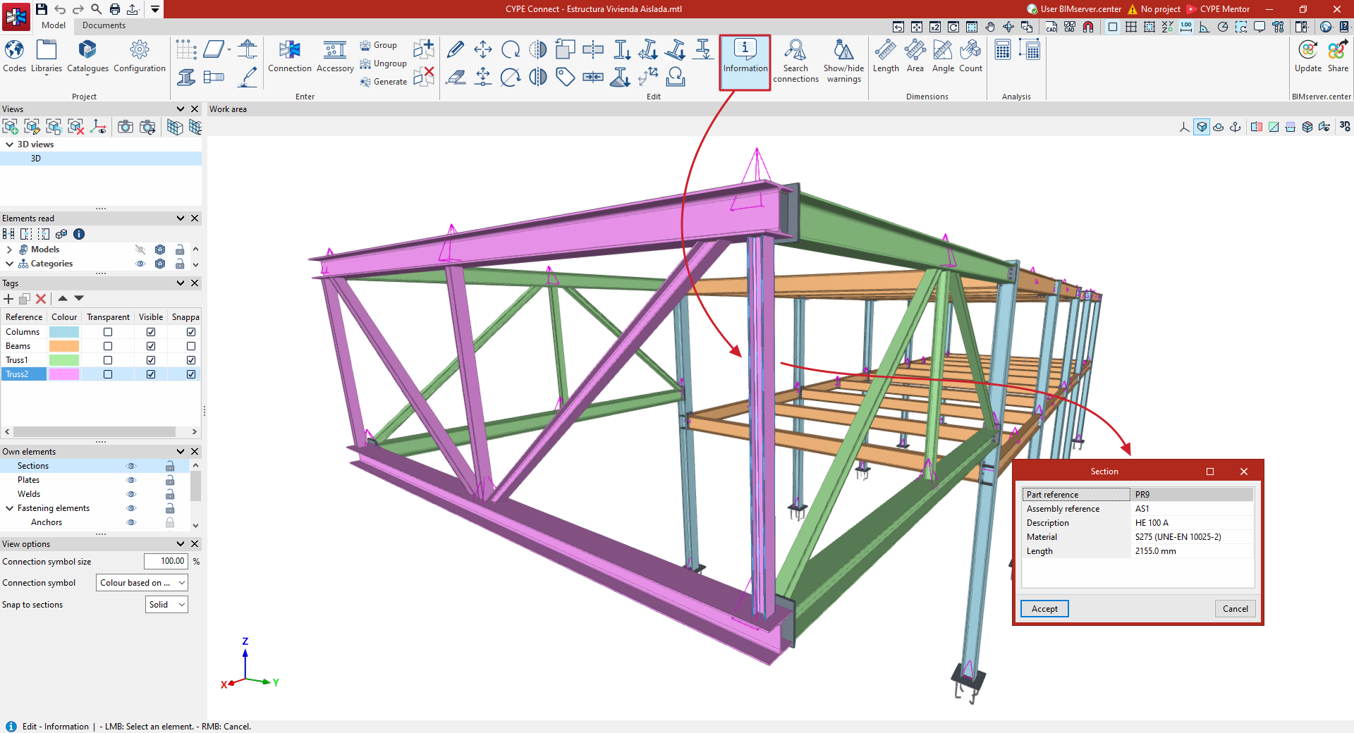
This option allows you to view information about the selected elements in the model in a pop-up window.
For example, the sections show the "Part reference", the "Assembly reference", the "Description", the "Material" and the "Length".
Search for connections
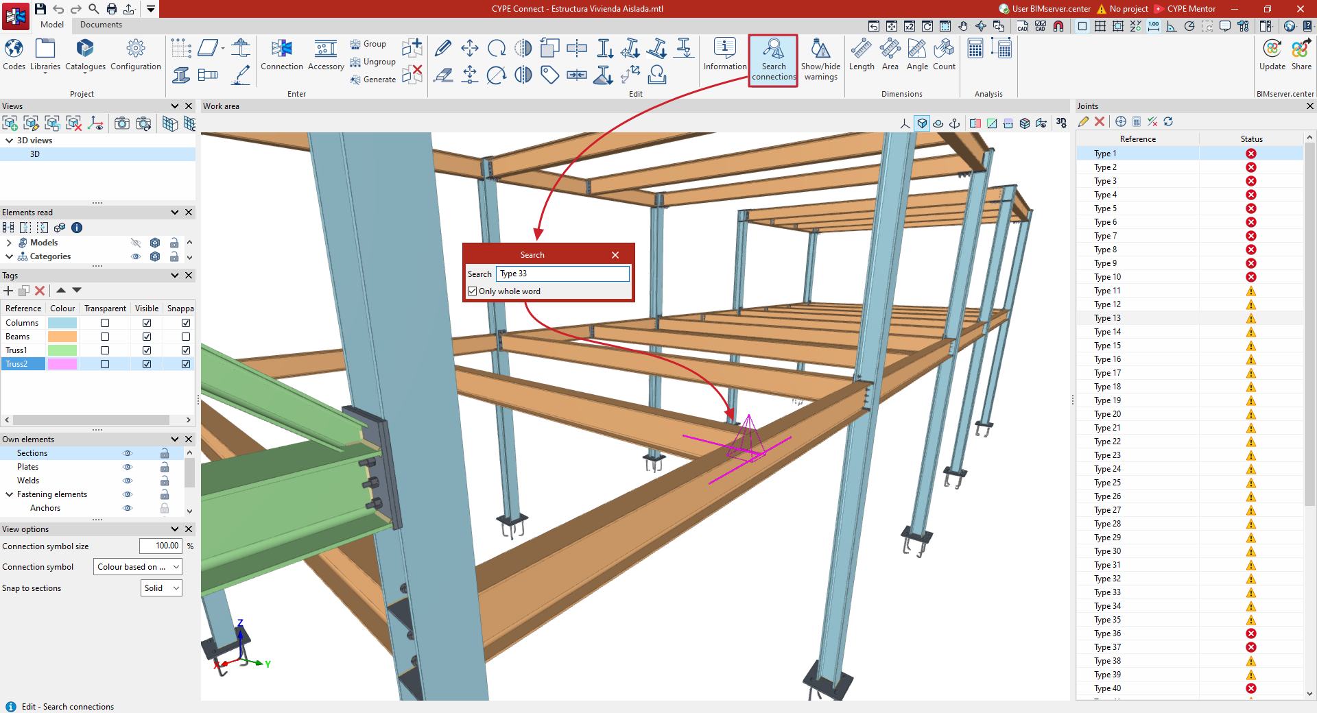
This option allows you to search for connections by entering part or all of their reference text.
To do this, when you run the tool, a panel appears where you can enter the reference number of the connection you wish to locate. Connections whose reference number matches the text entered either fully or partially will be highlighted in magenta, depending on whether the "Only whole word" option is enabled or not.
Show/hide notifications
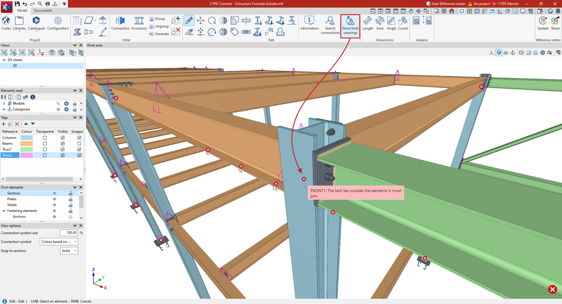
This option allows you to show or hide the symbols indicating warnings or errors that have occurred in the model.
Errors that occur while defining a connection in the connection editor are indicated by a marker placed over the connection.
Measurement tools in the "Model" tab
You can take measurements in the program's work area. To do this, go to the "Model" tab on the program's main interface and use the tools in the "Measurements" section of the top toolbar.

Length
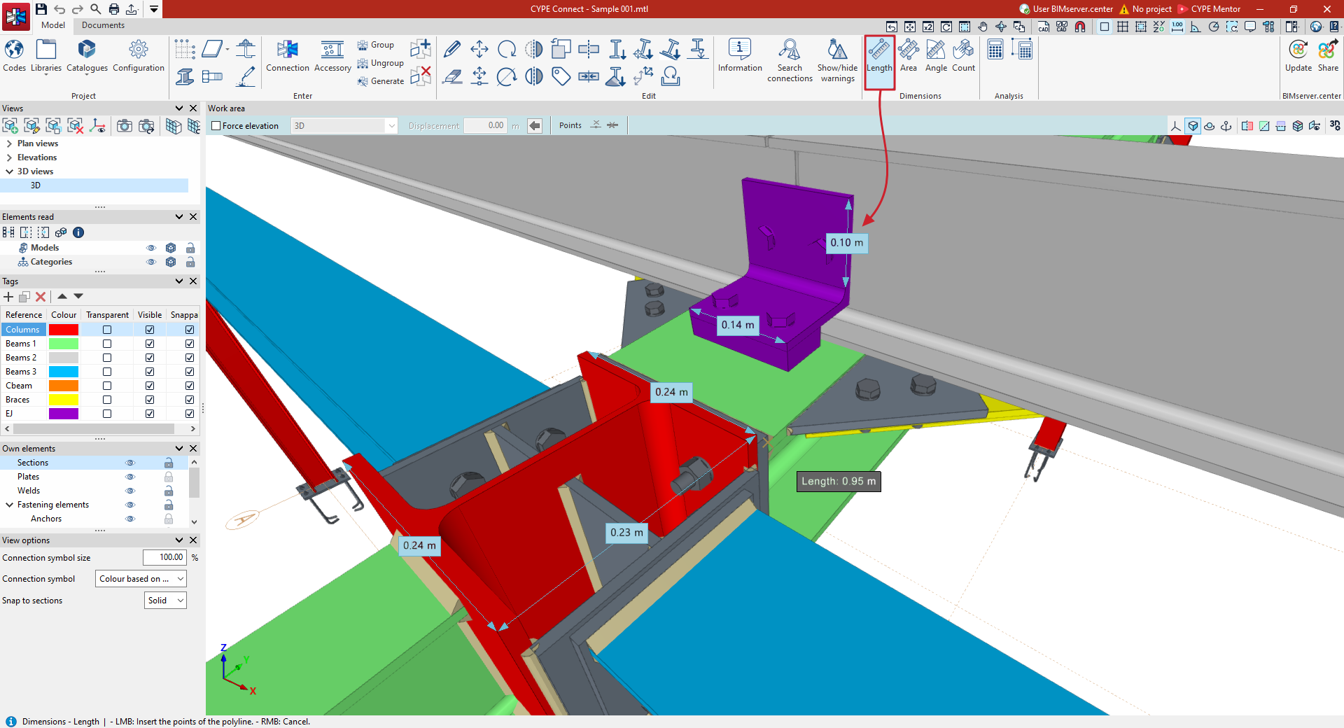
The first option available, "Length", allows you to measure the distance between several points.
After clicking on the option, use the left mouse button to mark two points on the model. The program will display the distance between them directly on the screen.
You can add several segments by clicking on further points in succession. When you do this, the app will calculate the sum of the lengths of each segment and display it next to the mouse cursor. To stop adding points, click the right mouse button. The sum of the lengths will then be displayed on the screen.
To clear the measurements, right-click again.
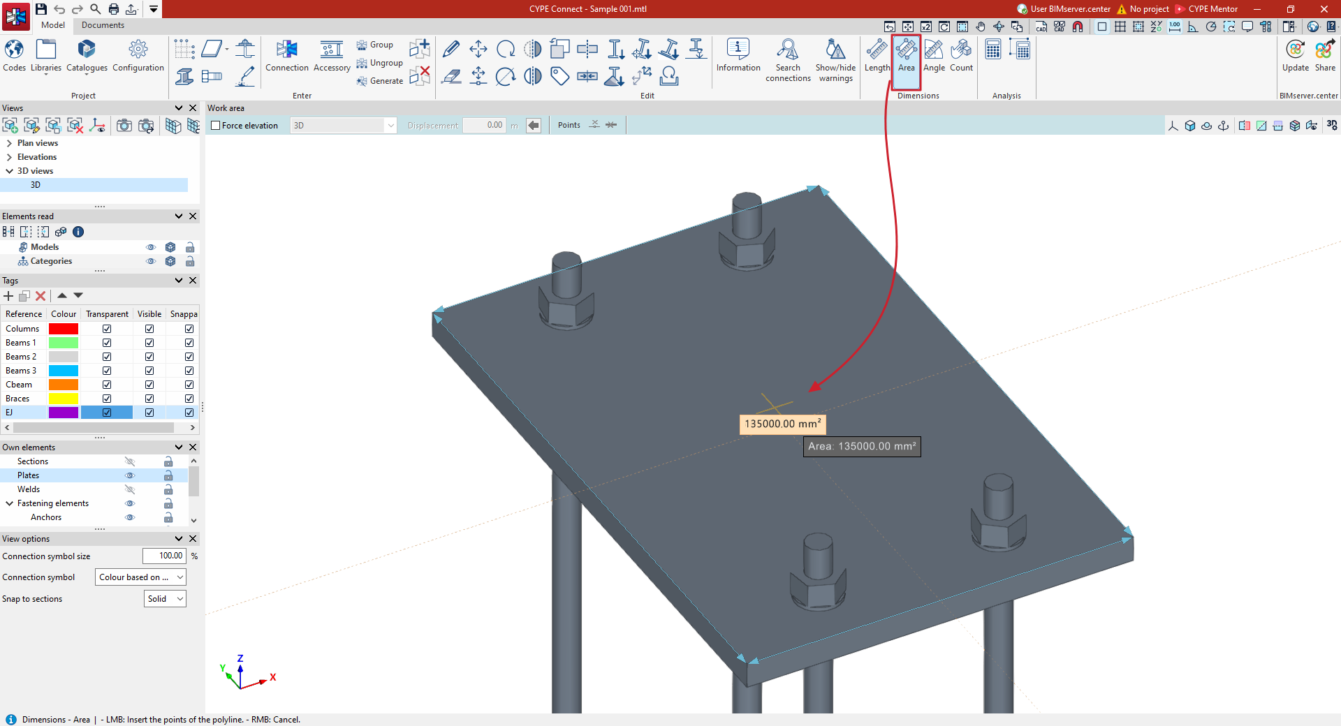
Area
The second option, "Area", allows you to measure the area of a polygon defined by points. To do this, use the left mouse button to select several points on the model that are on the same plane and form a closed outline. Then, click the right mouse button. The area of the polygon will appear on the screen.
You can enter several polygons consecutively. If you do so, when you right-click again, the app will calculate the sum of the areas of each polygon and display it next to the mouse cursor.
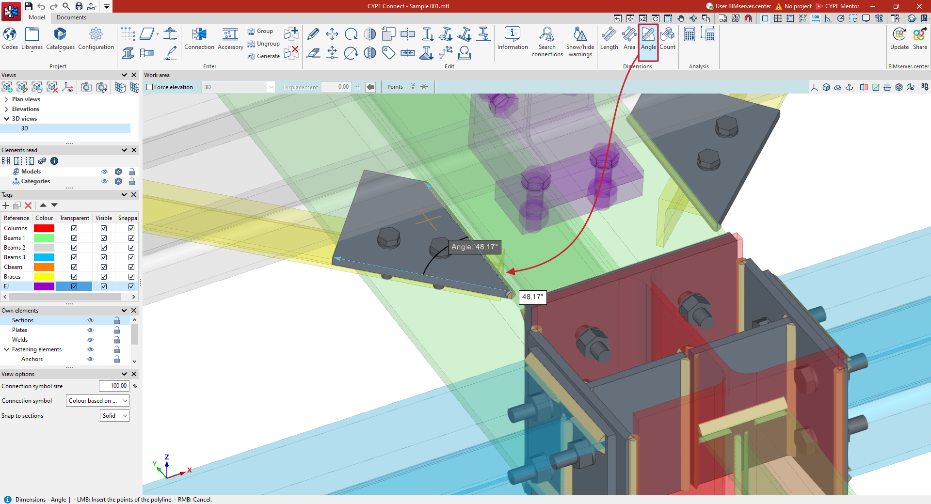
Angle
The following tool allows you to measure the "Angle" formed by three points. To do this, left-click to select the vertex of the angle and then select the two points that define its two sides. The value of the angle will appear on the screen next to its vertex.
You can enter several polygons consecutively. If you do so, when you right-click again, the app will calculate the sum of the areas of each polygon and display it next to the mouse cursor.
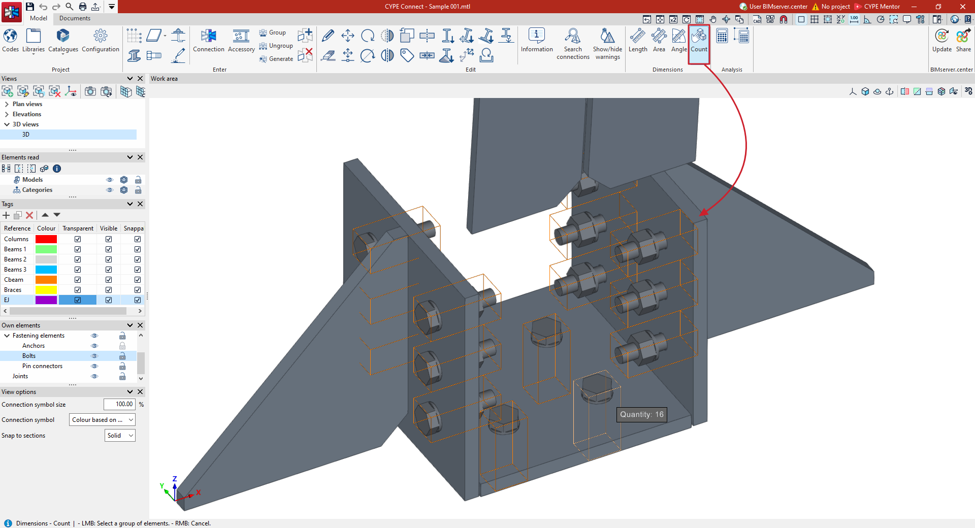
Count
Finally, the program allows you to "Count" the number of objects selected in the model. After clicking on the relevant option, you can select any of the model’s elements one by one using the left mouse button, or you can draw a selection area. The program will display the "Quantity" of selected elements next to the mouse cursor.
Analysing multiple connections
You can carry out the structural analysis and code compliance checks for multiple connections modelled in the program. To do this, go to the "Model" tab on the program's main interface and use the tools in the "Analysis" section of the top toolbar.

These options allow you to automatically analyse multiple connections at once, without having to access the editing and analysis panel for each connection individually.
Calculate all connections
Firstly, you can "Analyse all the connections". After selecting this option, the window that appears allows you to specify the "Analysis" you wish to perform by ticking the "Stress/Strain", "Rotational stiffness" or "Buckling" boxes. Then, click "Accept".
The program then begins an analysis process, analysing all the modelled connections in the structure, one by one.
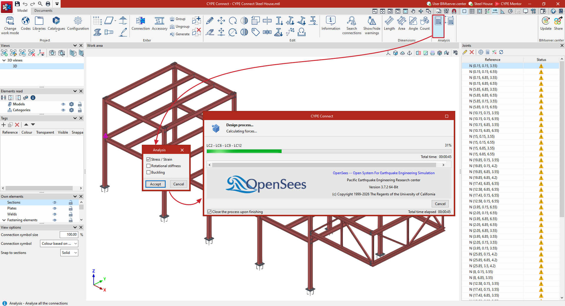
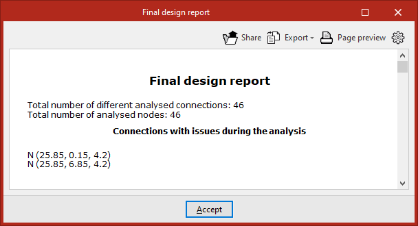
Once the analysis is complete, a "Final design report" is generated showing the results, including the "Total number of different analysed connections" and the "Number of analysed nodes", and highlighting any "Connections with issues during the analysis".
Analyse the selected connections
Secondly, you can "Analyse the selected connections". This option is useful for checking only those connections that have been modified.
After clicking on the option, select one or more connections with the left mouse button or with a selection area. Next, click the right-click button. In the window that appears, select the "Analysis" you wish to perform ("Stress/Strain", "Rotational stiffness" or "Buckling") and click "Accept".
The program begins the analysis process for the selected connections and, once completed, generates a "Final design report" containing the results.
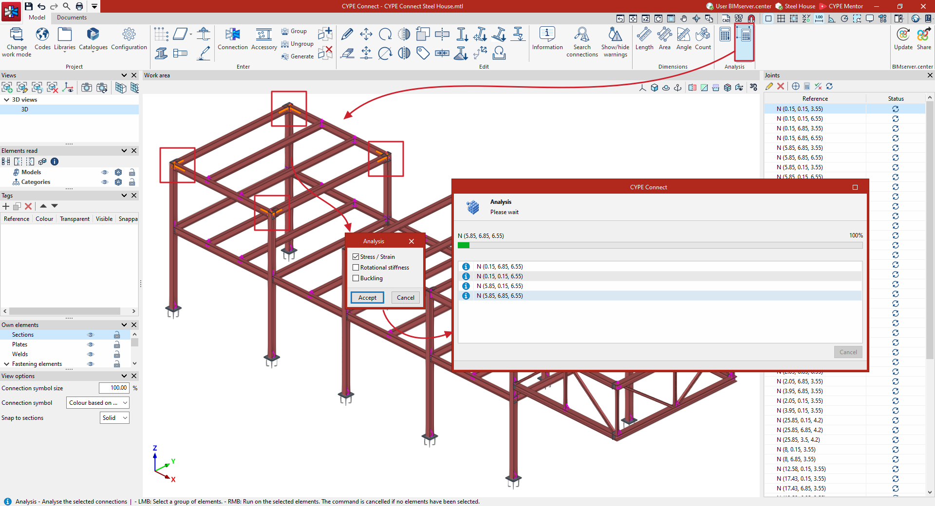
Table of contents
Complete your tour of CYPE Connect by exploring the other sections available:
